1.28 ESPHOME Lesson03 Adjusting Screen Brightness
Lesson03---Rotate the knob to adjust screen brightness
1. Course Introduction
In the previous lesson, we learned how to light up the rotary display, making it illuminate and show text. In this lesson, based on the previous one, we will learn how to rotate the knob to adjust the screen brightness.
2. Learning Objectives
How to drive the rotation function of the rotary display
Use the rotation function to control screen brightness
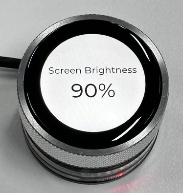
3. Project Running Effect
You can adjust the screen brightness by rotating the knob, and the current brightness value will be displayed on the screen in real time.
(Rotate clockwise to increase screen brightness, rotate counterclockwise to decrease screen brightness)
4. Example Code Download Link and Key Code Explanation
Click the GitHub link below to download the complete code:
Next, we will explain the key parts of this code and how code is written on the ESPHome platform to enable knob rotation and achieve screen brightness control.
In the following explanation, some related code configurations were already explained in detail in the previous lesson, so they will not be repeated here. Only the new code knowledge will be explained.
(1) Initialization Process (esphome block)
on_boot serves as the core initialization process after device startup (priority 800, ensuring execution after core components are ready but before user interaction). It first completes basic hardware initialization: outputting a log to indicate backlight startup, enabling the backlight PWM output channel and briefly delaying to allow hardware stabilization, then setting peripheral pin states according to the hardware baseboard requirements (turning off the power indicator LED and turning on out1/out2). It then waits for the display to complete power-on initialization, freezes encoder input via lambda code (to avoid misoperation during initialization), sets the initial brightness value to 50%, and resets the encoder’s internal count to 0. After that, it sets the backlight brightness to 50% through the light component, formats the brightness value into a percentage string via lambda code and updates the LVGL brightness label on the display, and forces a screen refresh to ensure the initial value of 50% is displayed correctly. Finally, it delays briefly to ensure the encoder reset takes effect, then unfreezes the encoder via lambda code, completing all startup-stage initialization of the backlight, encoder, and display, ensuring the device enters a normal interactive initial state after power-on (50% brightness, encoder ready).
on_boot:
priority: 800
then:
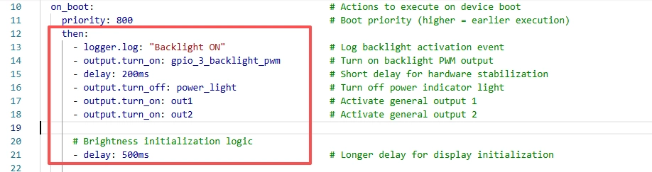
- logger.log: "Backlight ON"
- output.turn_on: gpio_3_backlight_pwm
- delay: 200ms
- output.turn_off: power_light
- output.turn_on: out1
- output.turn_on: out2
- delay: 500ms
- lambda: |-
id(encoder_ready) = false;
id(brightness_value) = 50;
id(knob).publish_state(0);
- light.turn_on:
id: back_light
brightness: 0.5
- lambda: |-
char buf[10];
snprintf(buf, sizeof(buf), "%d%%", id(brightness_value));
lv_label_set_text(id(lbl_brightness), buf);
lv_refr_now(NULL);
- delay: 200ms
- lambda: |-
id(encoder_ready) = true;
Key points of this code section:
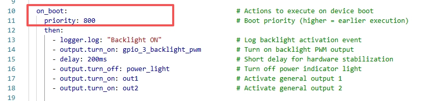
on_boot is the ESPHome startup hook, and priority indicates the execution order of this startup task. The larger the value, the earlier it executes.
Turn on the screen backlight gpio_3_backlight_pwm, turn on the power indicator light power_light, and enable the screen power supply pin and interface power supply pins out1 and out2. (Described in detail in the previous lesson)
Delay for 500 ms to wait for hardware initialization to complete.
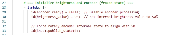
encoder_ready = false: temporarily disable knob events from modifying brightness.
brightness_value = 50: set the internal software brightness variable to 50%, matching the PWM output.
publish_state(0): set the internal count state of the rotary_encoder to 0 as well, keeping the knob logic consistent with the software variable.
This design prevents sudden “jumps” during knob initialization that could cause brightness to suddenly jump to 0 or 100. It ensures that the “knob position, internal brightness value, and actual PWM brightness” are fully aligned, which is a commonly used safe initialization strategy for knob-based brightness systems.
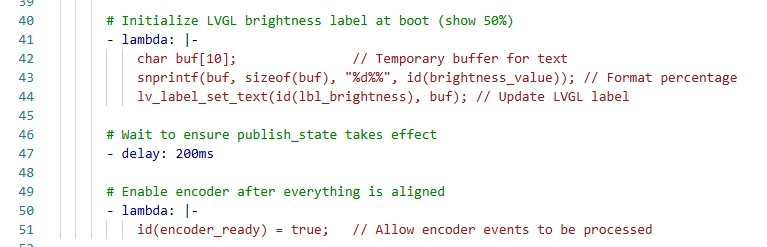
The purpose of this code is to initialize the brightness variable and the percentage text on the display to 50% at startup and show it via the LVGL label “lbl_brightness,” then wait 200 ms for the display and internal state to stabilize, and finally set “encoder_ready” to “true” to unlock the knob so it can respond to user operations. This design ensures synchronization between the screen display and the internal brightness value at startup, while preventing accidental knob input during initialization that could cause brightness jumps, achieving smooth and safe alignment between the UI display and control logic.
(2) Global Variables
Reminder again: many intermediate code sections were explained in detail in the previous lesson, and this lesson only explains the code related to the new functionality.
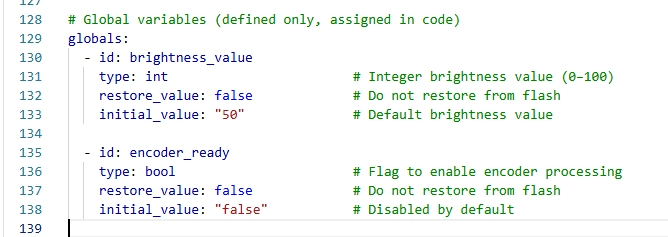
This “globals” code defines two global variables: “brightness_value,” used to store the current screen brightness as an integer (0–100), with an initial value of 50 representing the default startup brightness of 50%; and “encoder_ready,” a boolean flag used to control whether the knob can respond to user input, with an initial value of “false,” meaning the knob is temporarily disabled during startup or initialization to prevent accidental input. This design allows brightness and display initialization to complete first during system startup, and then safely enables user knob adjustment.
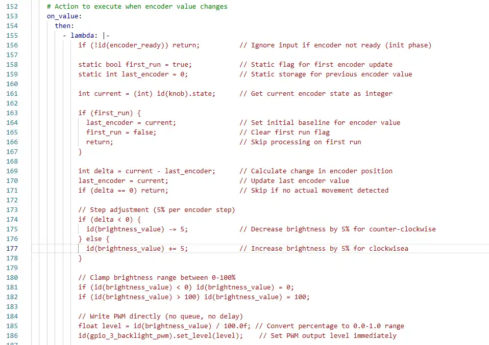
(3) Knob Encoder Configuration
First, complete the hardware-level configuration of the encoder by binding its A phase (CLK) and B phase (DT) to GPIO42 and GPIO4 respectively, enabling input mode and internal pull-up resistors to stabilize the signal, and setting the resolution to 1. Add a 20 ms debounce filter and a rounding filter to improve signal stability. When a value change triggers the on_value callback, the code first checks the encoder_ready variable to ensure system initialization is complete, then uses static variables to record the first execution state and the previous encoder value. It calculates the difference (delta) between the current and previous values to determine rotation direction: rotating left decreases brightness by 5%, rotating right increases it by 5%, with brightness clamped to the valid range of 0–100%. Finally, it writes the corresponding brightness level directly to the PWM output pin to control the backlight hardware in real time, formats the brightness percentage string, updates the LVGL display label, and forces a screen refresh to ensure the value is immediately visible.
sensor:
  - platform: rotary_encoder
    id: knob
    name: "Encoder"
    pin_a:
      number: 45
      mode:
        input: true
        pullup: true
    pin_b:
      number: 42
      mode:
        input: true
        pullup: true
    resolution: 1

    filters:
      - debounce: 20ms
      - lambda: return round(x);

    on_value:
      then:
        - lambda: |-
            if (!id(encoder_ready)) return;

            static bool first_run = true;
            static int last_encoder = 0;

            int current = (int) id(knob).state;

            if (first_run) {
              last_encoder = current;
              first_run = false;
              return;
            }

            int delta = current - last_encoder;
            last_encoder = current;
            if (delta == 0) return;

            if (delta < 0) {
              id(brightness_value) -= 5;
            } else {
              id(brightness_value) += 5;
            }

            if (id(brightness_value) < 0) id(brightness_value) = 0;
            if (id(brightness_value) > 100) id(brightness_value) = 100;

            float level = id(brightness_value) / 100.0f;
            id(gpio_3_backlight_pwm).set_level(level);

            char buf[10];
            snprintf(buf, sizeof(buf), "%d%%", id(brightness_value));
            lv_label_set_text(id(lbl_brightness), buf);
            lv_refr_now(NULL);
Key explanation of this code section:
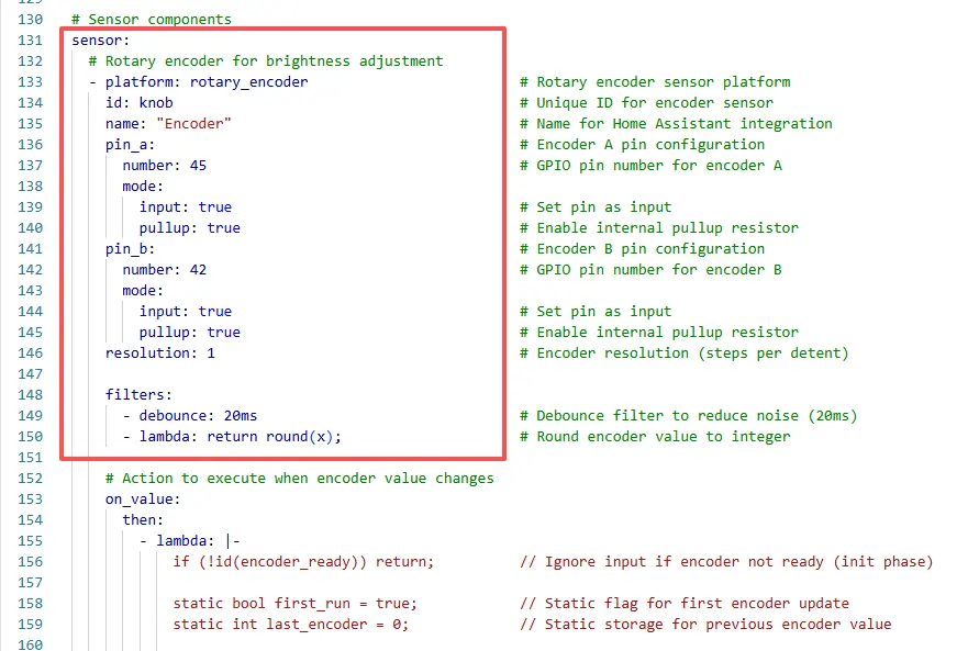
This code defines a rotary encoder sensor used to read the rotation state of the physical knob, assigns it the unique ID “knob,” names it “Encoder,” and marks it as an internal sensor (used only locally and not exposed to external platforms).
It then configures the encoder’s core hardware pins by binding the A phase (CLK clock line) to GPIO45 and the B phase (DT data line) to GPIO42, both set as input mode to read encoder pulse signals, and enables internal pull-up resistors to prevent floating pins from causing voltage fluctuations and false triggers.
Next, two levels of signal filtering are added: a 20 ms debounce filter to eliminate mechanical jitter noise during rotation, and a rounding filter to convert the encoder’s floating-point output into integers, simplifying subsequent calculations.
Finally, the encoder resolution is set to 1, meaning each mechanical detent rotation changes the value by only one step, ensuring precise signal reading and simplified computation, laying a solid hardware and signal-processing foundation for stable and accurate encoder output.
This code is the core logic of the on_value callback triggered when the rotary encoder value changes in the ESPHome framework. It fully implements the entire process from encoder signal parsing to backlight brightness adjustment and LVGL UI synchronization, and includes multiple fault-tolerance and initialization protection mechanisms. The logic can be broken down as follows:
First, the global boolean variable encoder_ready is used for initialization protection. If the system startup initialization has not completed (this variable is false), all encoder processing logic is skipped to avoid accidental operations during startup.
Next, two static variables are defined (first_run as a first-execution flag and last_encoder as the previous encoder value). These variables retain their values across multiple callback executions. The current encoder value is read and converted to an integer.
If this is the first execution of the callback, last_encoder is synchronized with the current encoder value, the first_run flag is cleared, and the function exits without performing any brightness adjustment, ensuring encoder state alignment during initialization. Then, the difference delta between the current and previous values is calculated (the core basis for determining rotation direction and step count), and last_encoder is updated for the next calculation. If delta is 0 (no valid rotation), the function exits directly to reduce unnecessary computation.
Based on the sign of delta, the rotation direction is determined: rotating left (delta < 0) decreases the global brightness variable brightness_value by 5%, while rotating right (delta > 0) increases it by 5%. The brightness value is strictly clamped to the valid range of 0–100% to prevent exceeding hardware-supported limits. The percentage brightness value is then converted to a 0.0–1.0 PWM level and written directly to the backlight PWM output pin (bl_pwm), achieving immediate hardware-level brightness control without queuing or delay.
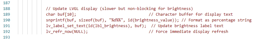
Finally, a temporary character buffer is created to format the brightness value as a percentage string (such as “50%”), update the brightness display label text in the LVGL interface, and call lv_refr_now(NULL) to force a screen refresh, ensuring the UI display is synchronized with the actual backlight brightness in real time.
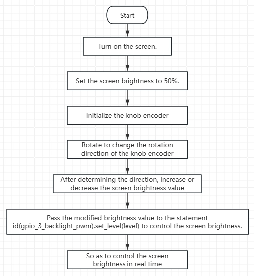
Summary: You rotate the encoder → The encoder outputs A/B phase pulse signals → The ESP32 reads the signals and converts them into digital values → The code calculates the rotation direction / step count and adjusts the brightness value → The brightness value is converted into a PWM signal to control the backlight current → The screen brightness changes in real time, and at the same time, the LVGL interface synchronously displays the percentage of brightness.
The key point of this process is: the encoder only “tells the MCU the direction and step count of rotation,” while the actual brightness control is performed by the PWM signal output from the ESP32. The encoder is an “input device,” the PWM output is a “control method,” and they are connected through software logic, achieving the intuitive interaction of “rotating the knob → brightness change.”
The “lambda” usage here is an inline C++ code block syntax provided by ESPHome, allowing you to write C++ logic directly in YAML. It lets you access ESPHome-defined global variables (such as “id(brightness_value)”) and sensor objects (such as “id(knob)”), enabling flexible handling of sensor events, calculations, conditional logic, and UI updates without writing separate external C++ files.
(4) LVGL Configuration
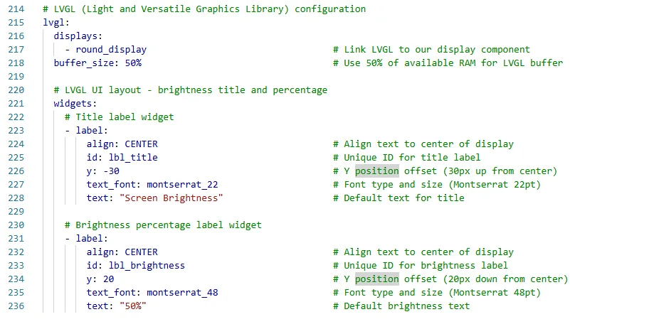
This code configures the use of the LVGL graphical user interface library in ESPHome. It binds the display “my_display” to LVGL and allocates 50% of the buffer for interface rendering, then creates two label controls: the first label, “lbl_title,” is centered at the top of the screen and displays the title “Screen Brightness” using the “montserrat_28” font.
The second label, “lbl_brightness,” is centered below and uses the larger “montserrat_48” font to display the current brightness percentage, with an initial text of “50%,” allowing the screen to simultaneously show the interface title and the brightness value controlled by the knob, providing a user-friendly real-time feedback interface.
5. Code Logic Flowchart
6. Flashing Steps
Next, we will teach you how to write code using ESPHome, including the overall operation process. Please follow us step by step.
Here we emphasize again:
The following devices need to be on the same LAN:
① Your computer
② CrowPanel HMI ESP32 Rotary Display
③ Raspberry Pi with the Home Assistant system
In this project, the Raspberry Pi with the Home Assistant system acts as the server, so every time you access the IP address of this Raspberry Pi with the Home Assistant system, you are accessing Home Assistant.
Only after entering this page can you proceed with the following operations.
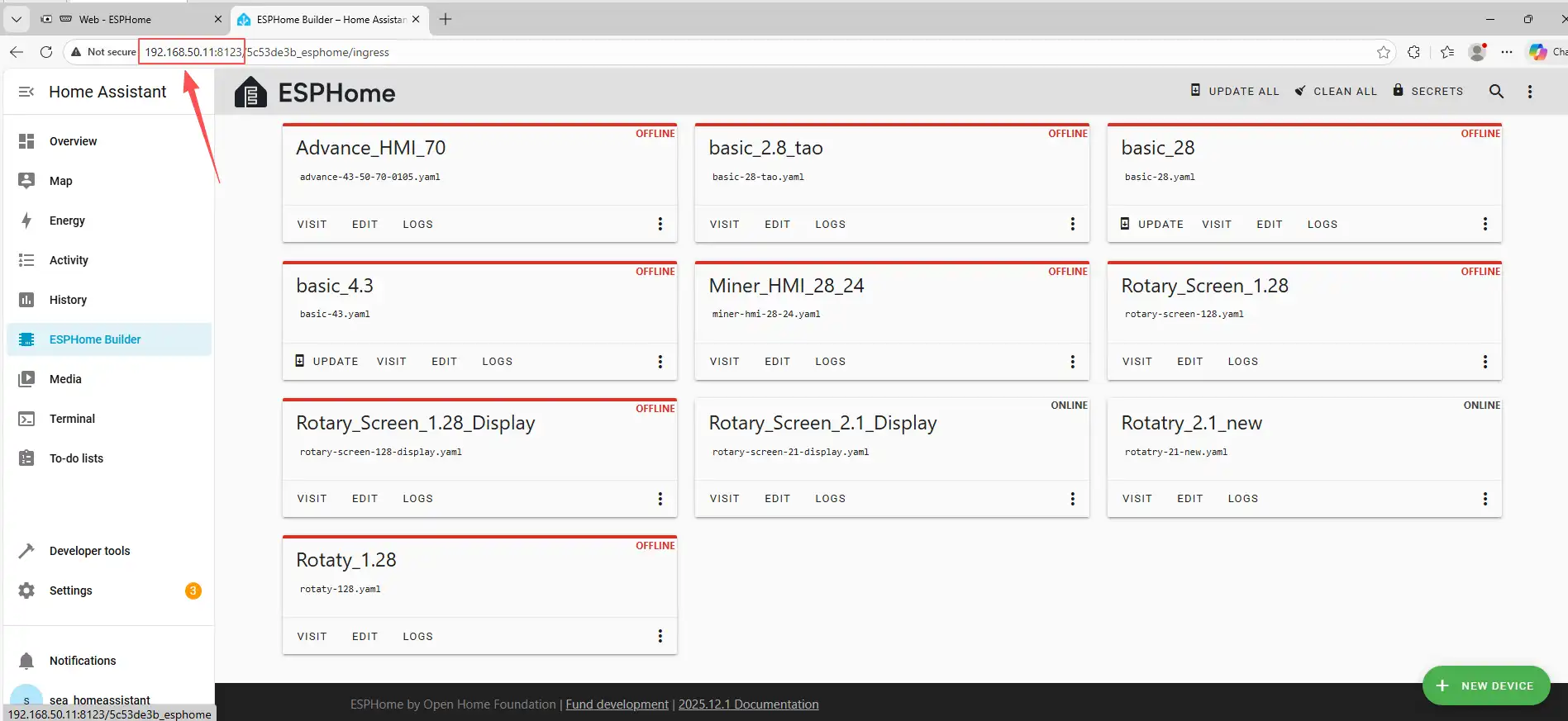
The following operations assume that you have completed the installation steps in Lesson 1 and have arrived at the ESPHome main page.
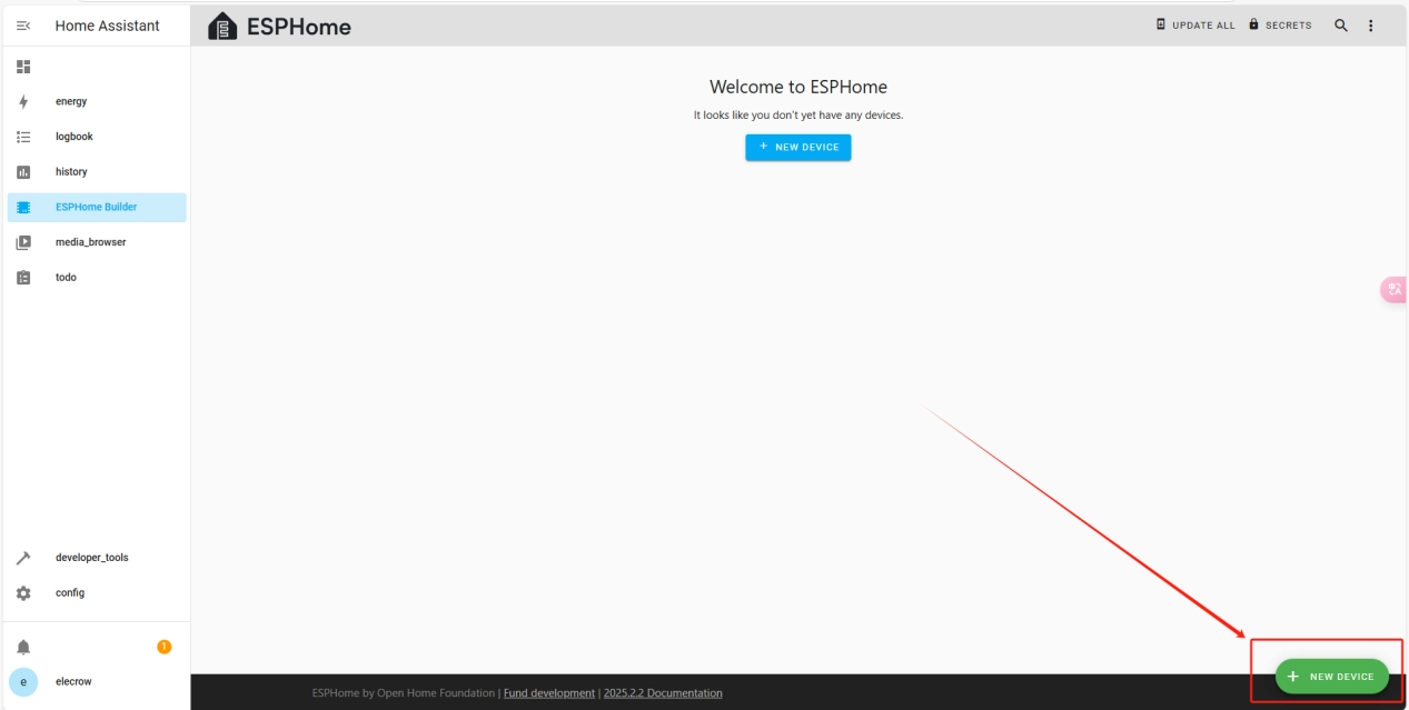
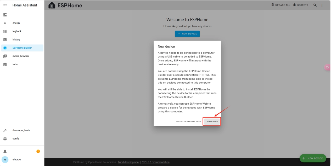
Once the installation is complete, we can start adding devices. Click on + New Device -> Continue.
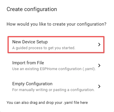
Click “New Device Setup.”
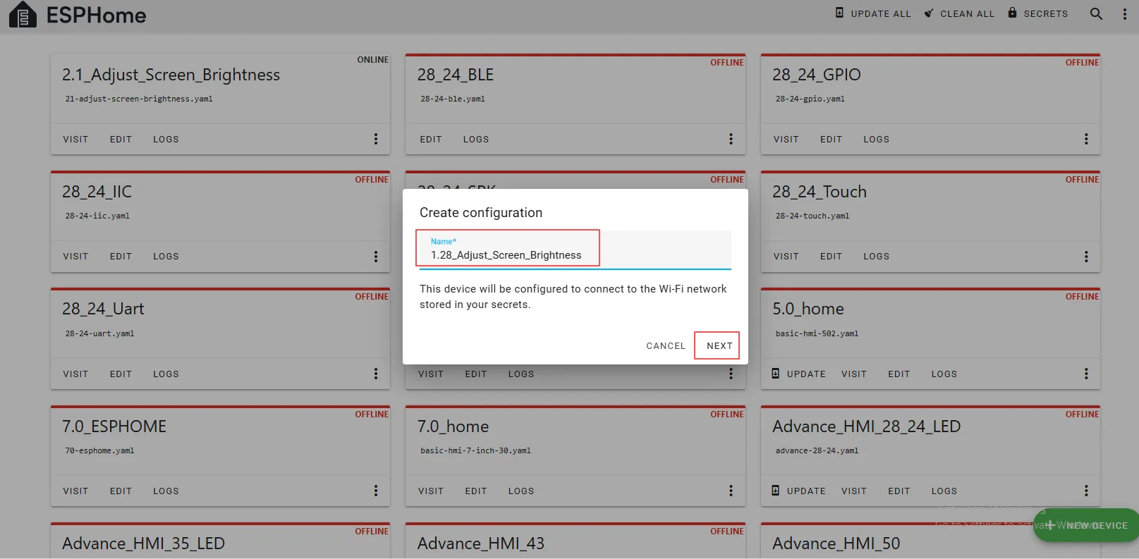
Enter a name and click Next.
(You can use any custom name. Do not include any strange symbols such as @, #, etc.)
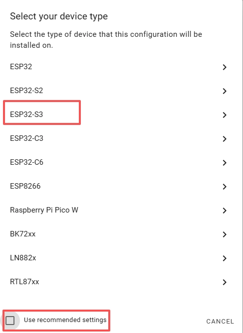
Here, do not check “Use recommended settings.”
Select the main chip of the CrowPanel 1.28inch-HMI ESP32 Rotary Display, ESP32-S3.
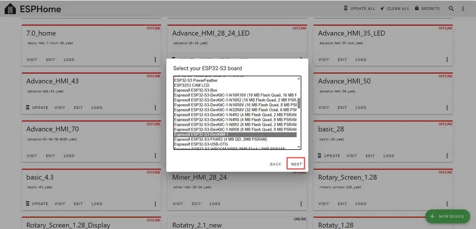
Next, choose any option (since we will replace it in the code later).
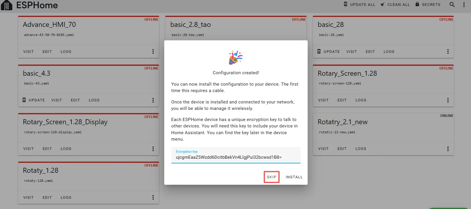
Here, click “SKIP.”
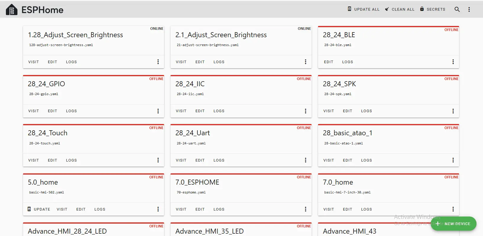
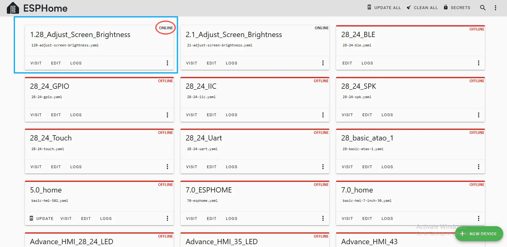
Then return to the main interface, find the 1.28_Adjust_Screen_Brightness you just created, click “EDIT,” and enter the code editor.
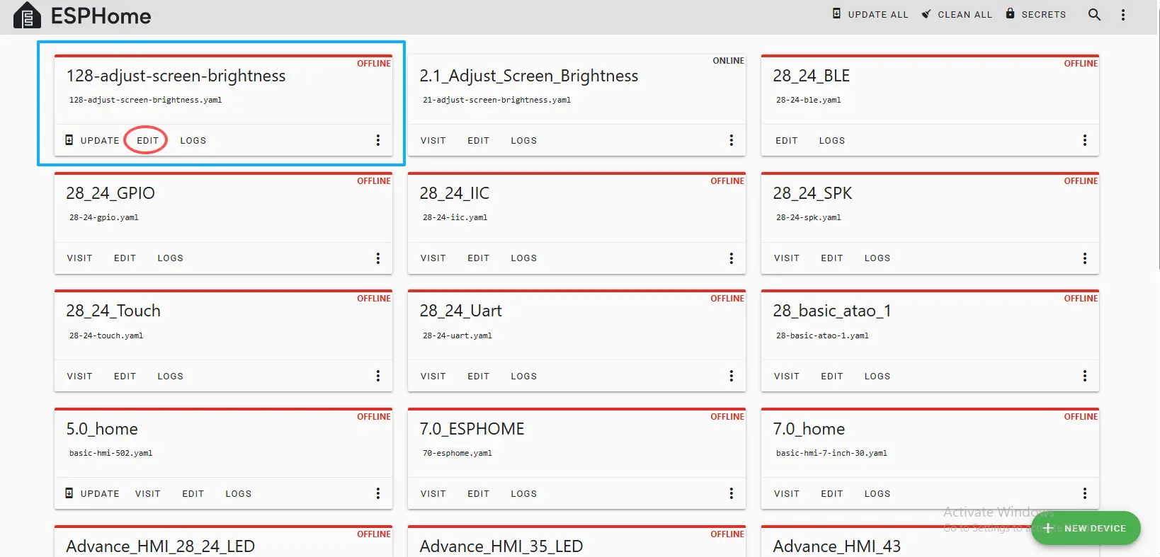
This code is automatically generated based on the previous steps. Next, we will make replacements in it to help optimize the code for more efficient operation.
Automatically generated code:
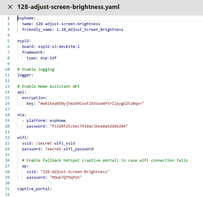
This is the complete code. You can click the code link below to obtain it.
Next, you can replace the relevant content in esphome and ESP32 as needed, and add the item “PSRAM.”
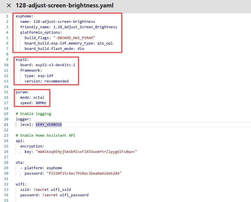
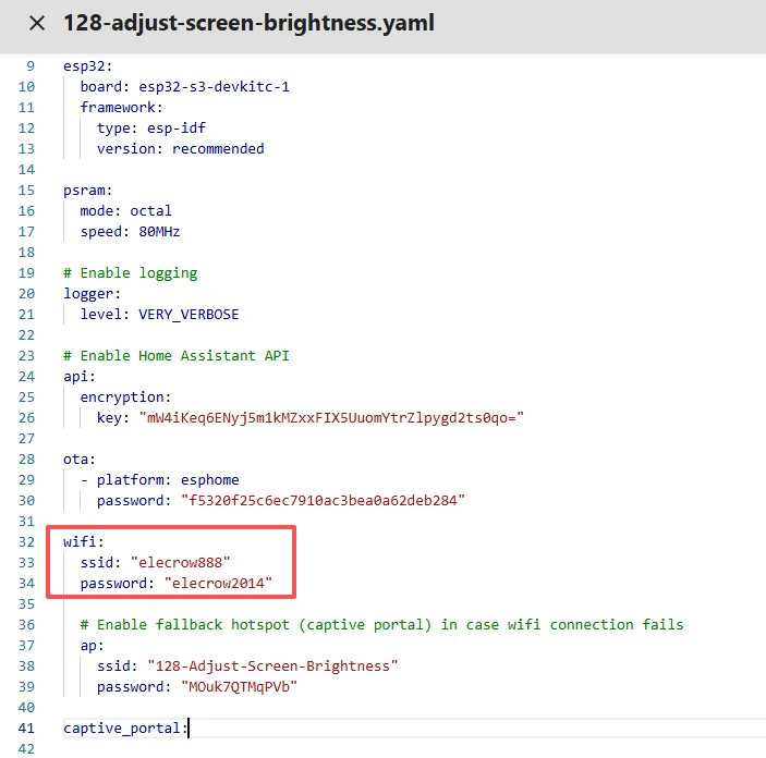
Then, based on your existing code, follow the format shown in the figure to add or replace these codes.
(Other configurations remain unchanged)
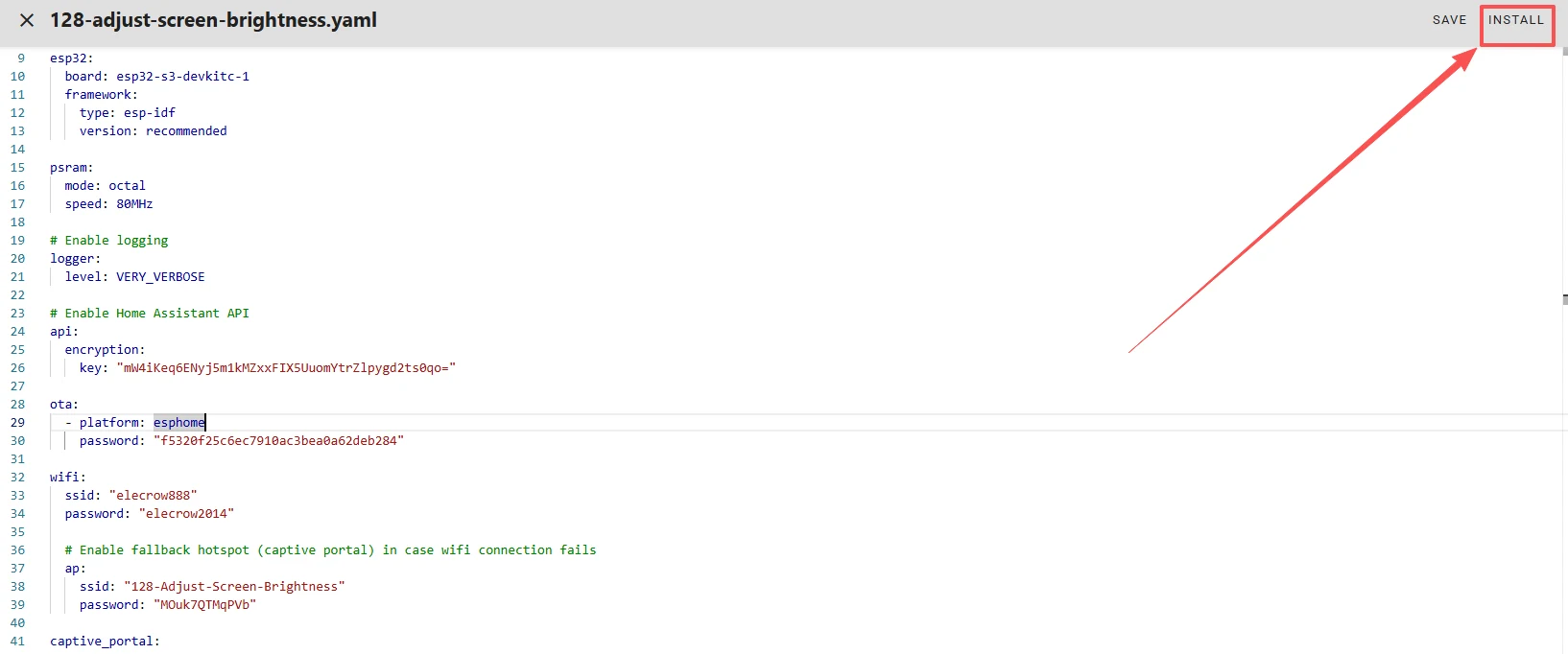
Remember to replace your own Wi-Fi name and password.
Note: This Wi-Fi connection must be in the same local network as your computer and Raspberry Pi!
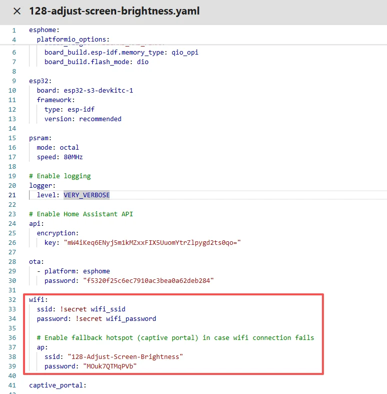
Here, our Wi-Fi account and password are set on the ESPHome main page.
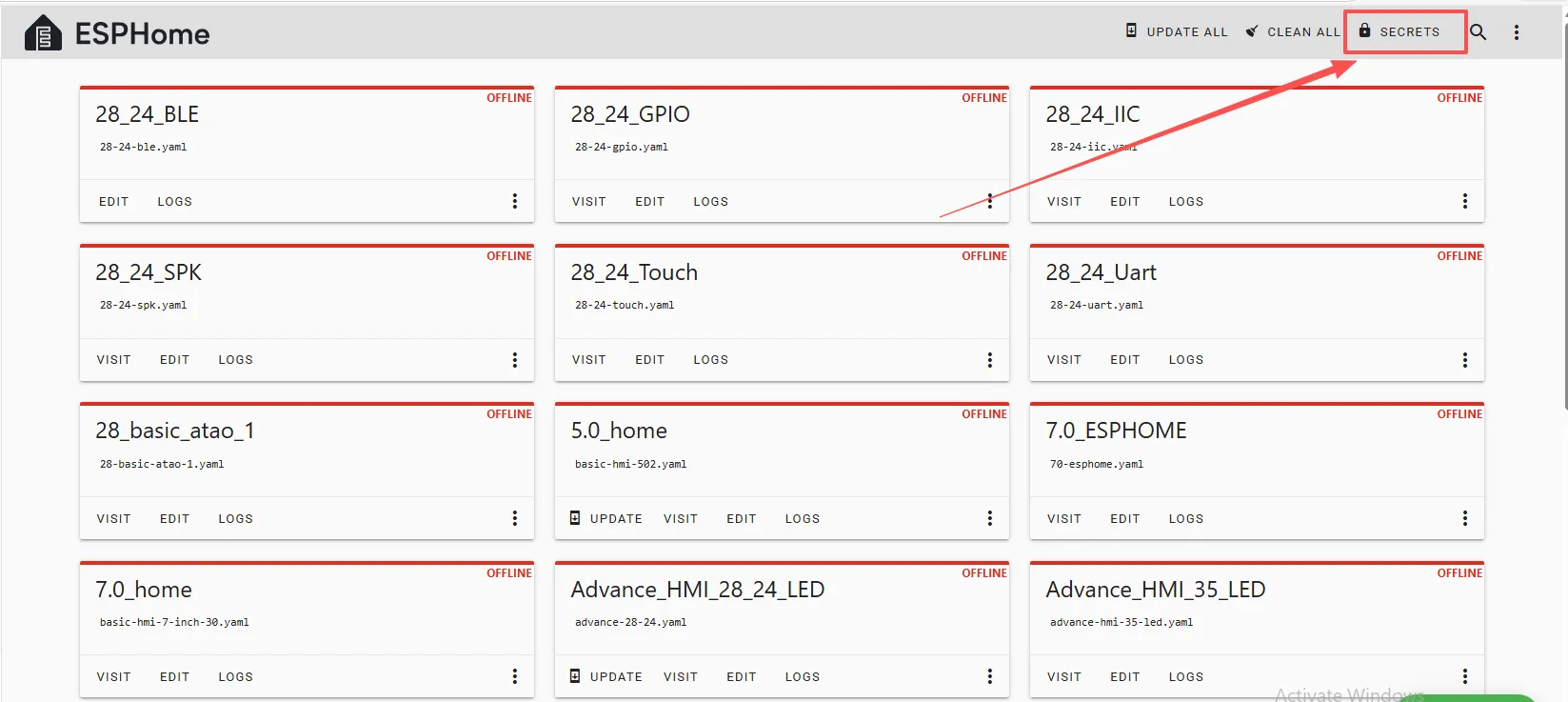
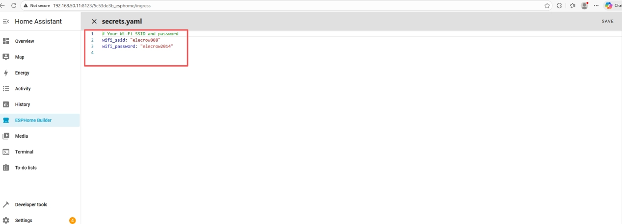
So we can write it this way in the code, meaning we are using the Wi-Fi “elecrow888.”
Of course, you can also explicitly write the Wi-Fi account and password in the code if you prefer.
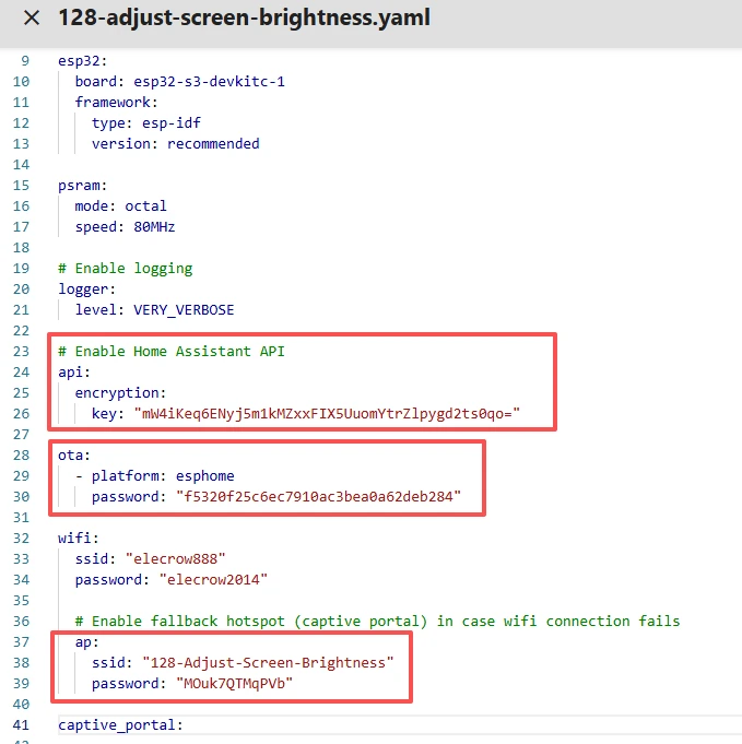
Note: These items are exclusive to the device you created and must not be the same as mine. Just keep the ones you originally created.
You can copy the other functional code from mine.
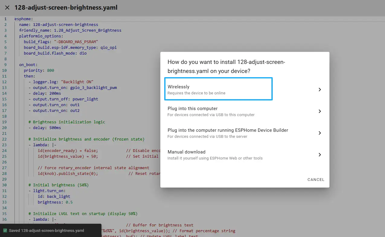
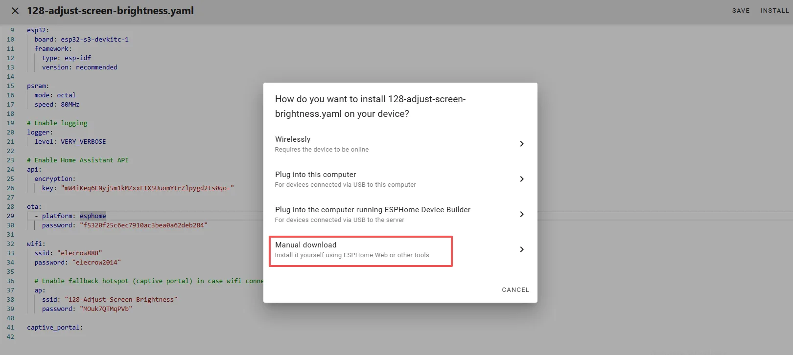
Once the code replacement is complete, click “INSTALL” in the top right corner.
Select “Manual download.”
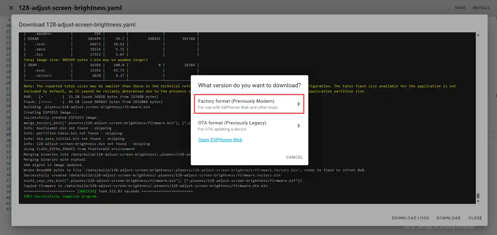
Wait for a few minutes until the installation is complete.
Then select “Factory format.”
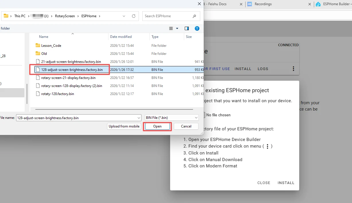
Once the download is complete, you will see the .bin file.
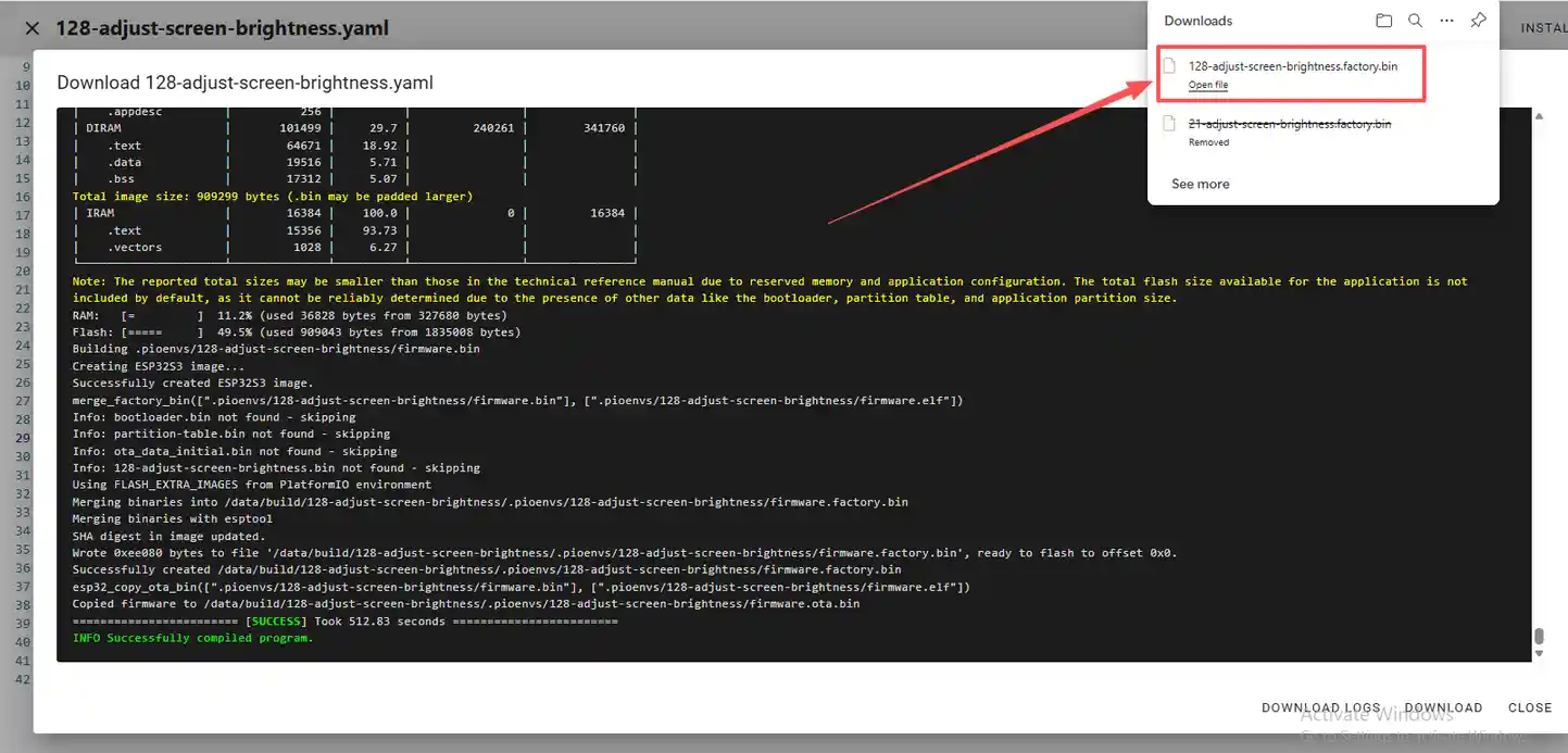
Remember the path of this .bin file.
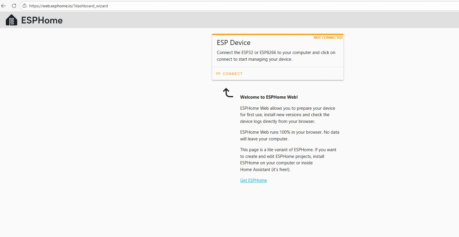
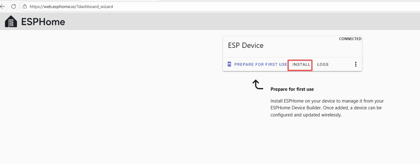
Open the following website: https://web.esphome.io/?dashboard_wizard
After opening this website, you will arrive at this interface:
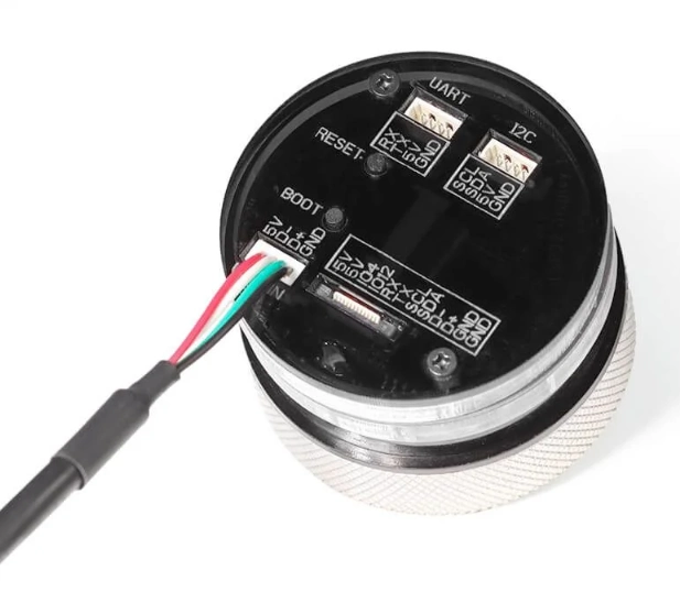
Next, we will flash this .bin file into the CrowPanel 1.28inch-HMI ESP32 Rotary Display.
Connect the CrowPanel 1.28inch-HMI ESP32 Rotary Display to your computer.
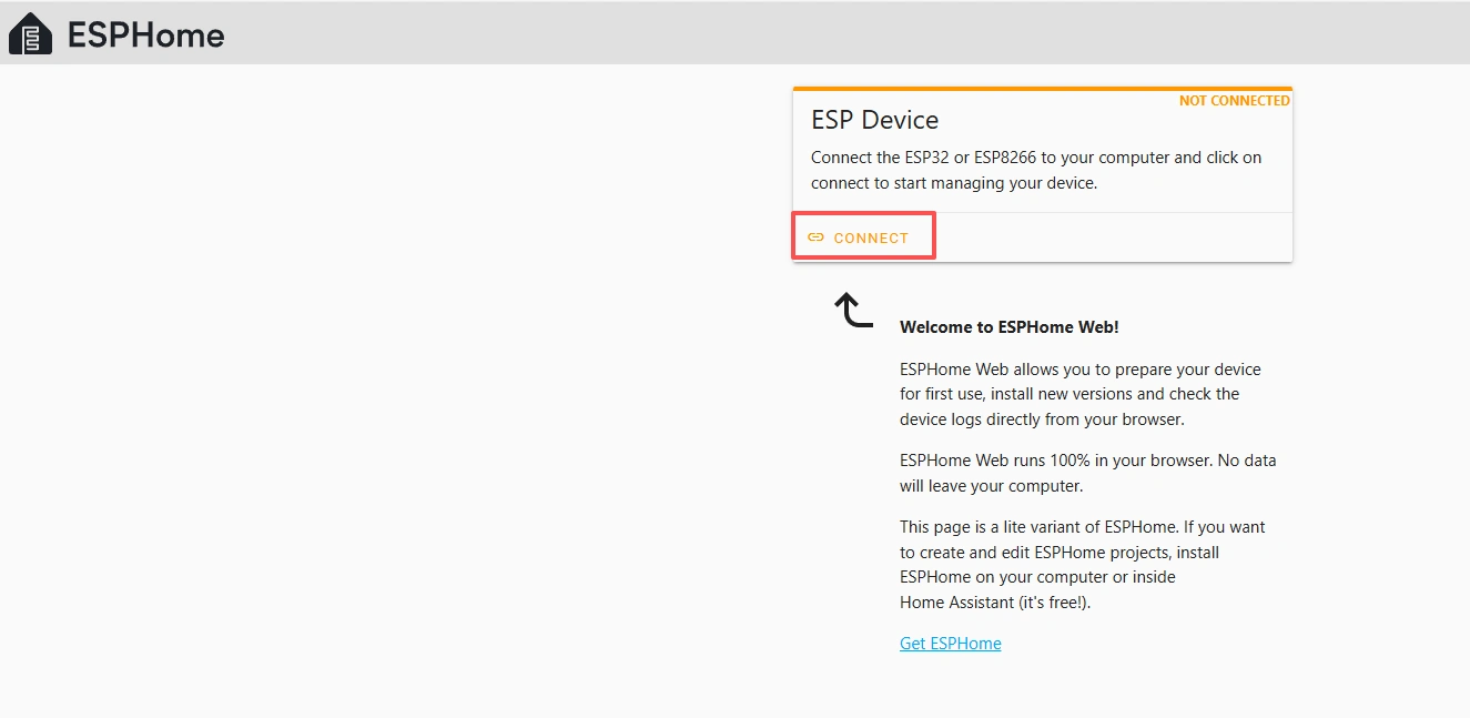
Click “Connect.”
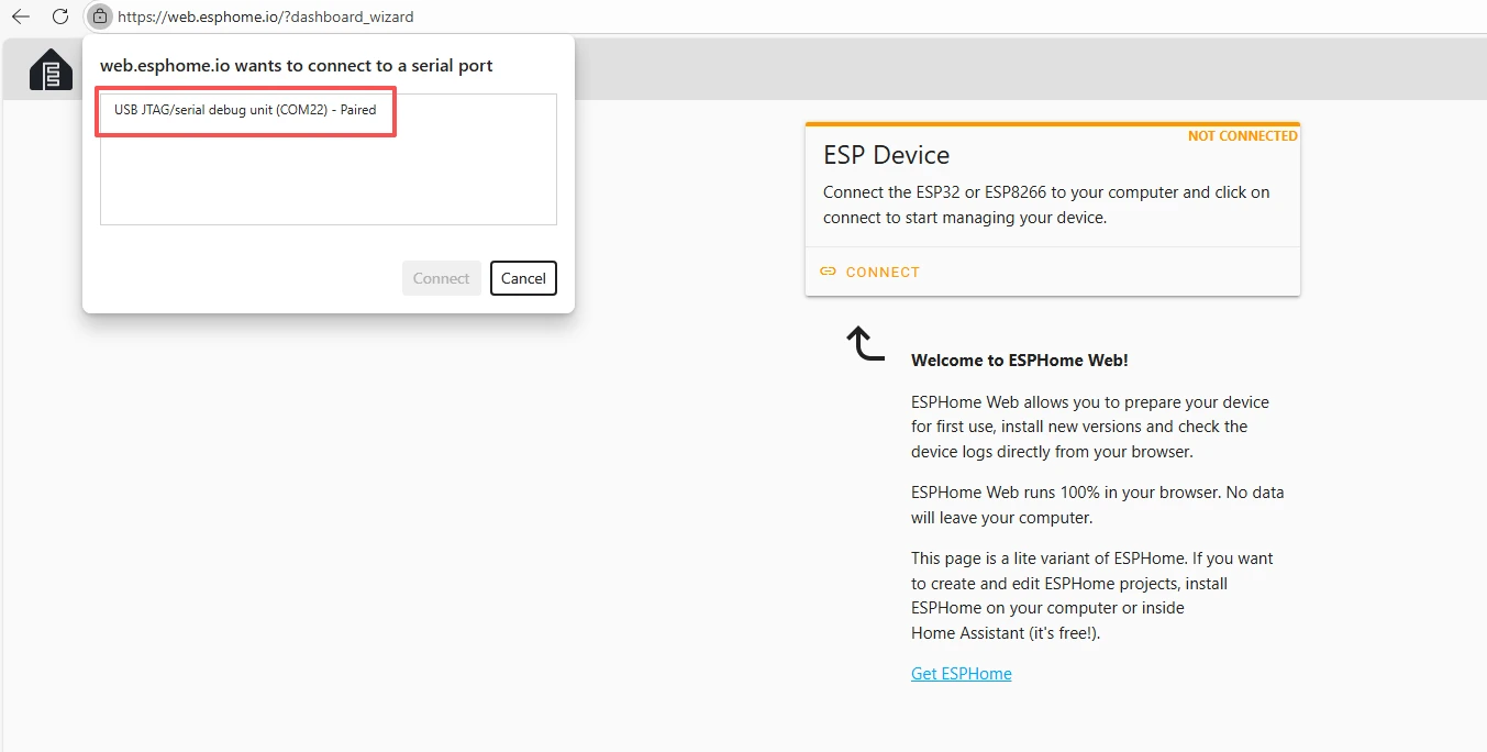
Select the COM port and connect it.
After connecting the CrowPanel 1.28inch-HMI ESP32 Rotary Display, click “Install.”
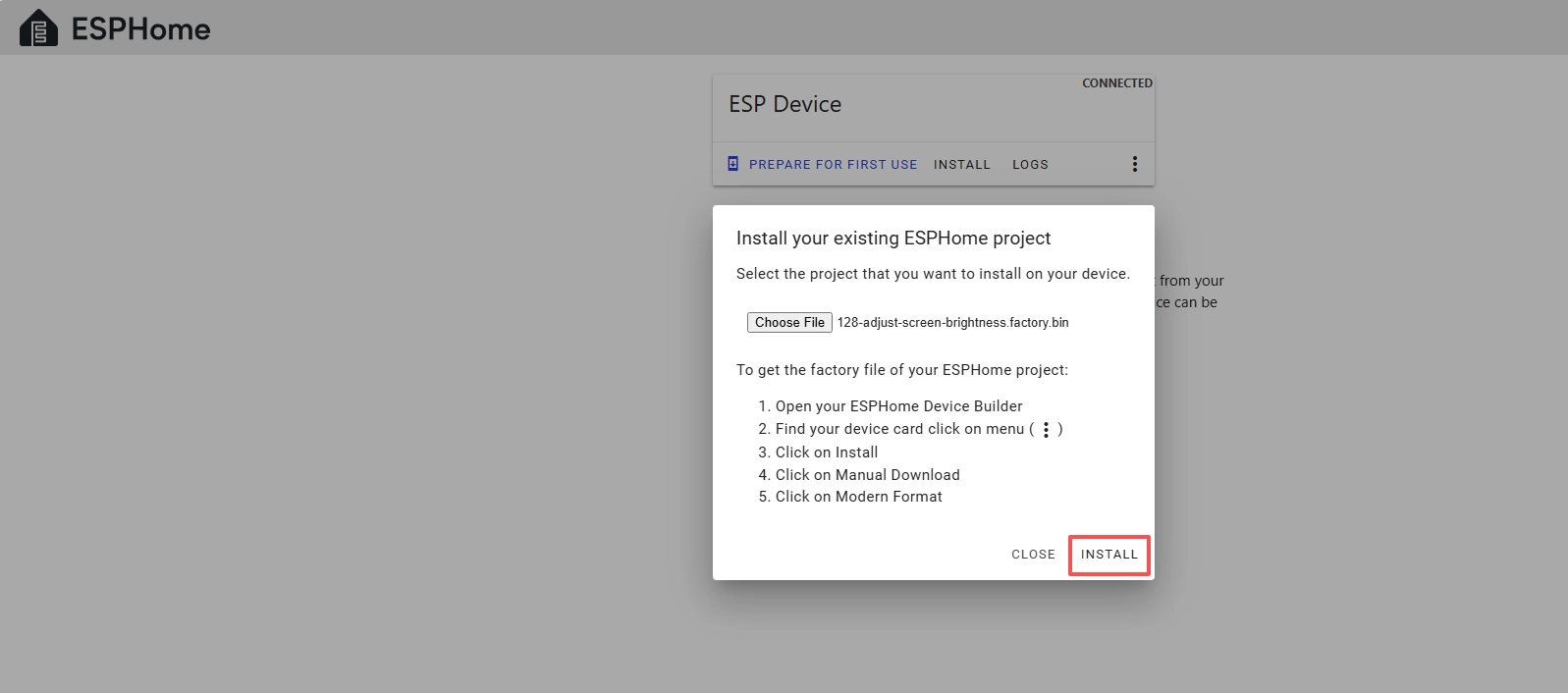
Add the .bin file you just downloaded, then click “Install.”
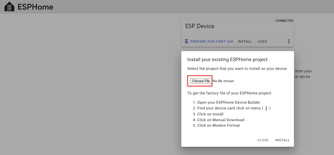
Then select the .bin file that you just downloaded.
Click “INSTALL.”
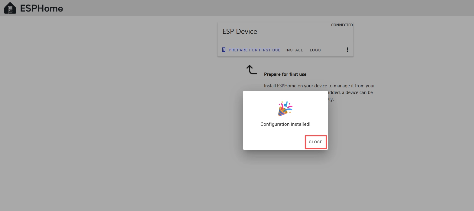
Wait for a few minutes.
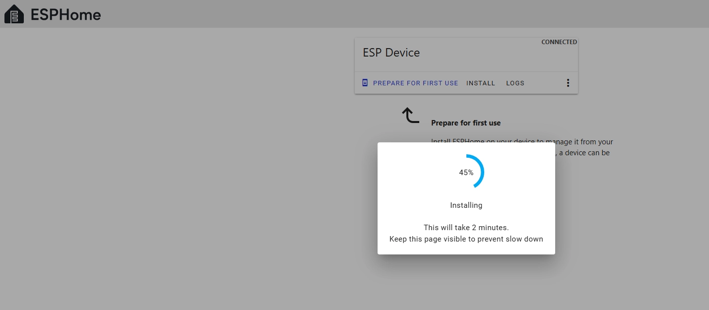
After the installation is complete, click “Close.”
After successfully flashing the .bin file, return to the ESPHome page in Home Assistant.
Press the RESET button on the CrowPanel 1.28inch-HMI ESP32 Rotary Display.
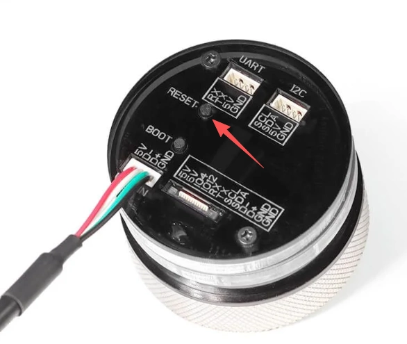
Restart the ESP32 display, and you should see the device you created earlier show as ONLINE in the top right corner.
If you have also added the functionality provided in our code, you will be able to see the current screen brightness value displayed on the screen, and you can try rotating the knob to see the screen brightness change in real time.

After ONLINE is displayed, any subsequent code modifications can be uploaded via wireless upload, which will be much more convenient.