2.1 ESPHOME Lesson02 Light Up the Screen
1. Course Introduction
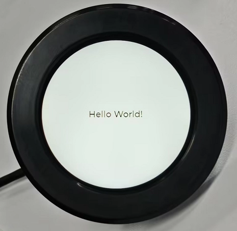
In this lesson, we will use ESPHome to write code to light up the CrowPanel 2.1inch-HMI ESP32 Rotary Display and display “Hello World” on the screen.
2. Learning Objectives
Learn how to drive the rotary display
Light up the screen and print hello world on the screen
3. Project Demonstration
4. Case Code Download Link and Key Code Explanation
Click the GitHub link below to download the complete code:
Next, we will explain the key parts of this code and how the screen is driven for display on the ESPHome platform.
First, establish a core understanding
This code is not traditional “programming code” (such as Python/C++), but an ESPHome configuration file (YAML format) — you can think of it as an “instruction manual” written for the ESP32: telling the ESP32 what hardware to connect to, what functions to implement, and how to communicate with Home Assistant.
The core rule of YAML is to describe the required program configuration in a text format similar to writing an instruction manual, rather than writing complex code. In YAML, indentation represents hierarchical relationships — content at the same level must align to the left, and child content must be indented two spaces more than the parent (Tabs are not allowed). The program determines “who belongs to whom” based on indentation; each line is usually in the form of key: value, where the left side of the colon is the name and the right side is the specific content; if a key contains multiple items, use - to represent a list; comments use #, which are only for human reference and are not executed; YAML is highly sensitive to case and spaces, and even one missing space or an extra Tab may cause the configuration to fail.
(1) Basic Information & Compilation Configuration (esphome block)
This is the “identity card” and “compilation rules” of the entire device, telling ESPHome how to compile the firmware and what the device is named.
esphome:
  name: rotary-screen-21-display
  friendly_name: Rotary_Screen_2.1_Display
  platformio_options:
    build_flags: "-DBOARD_HAS_PSRAM"
    board_build.esp-idf.memory_type: qio_opi
    board_build.flash_mode: dio
  on_boot:
    priority: 800
    then:
      # Bring up panel power before toggling RESET, then small delays. Based on Elecrow sample code, though colors are off
      - output.turn_on: lcd_power
      - output.turn_on: display_reset
      - delay: 100ms
      - output.turn_off: display_reset
      - delay: 100ms
The esphome configuration block is the core foundational configuration of the 2.1-inch rotary display device. It defines both the system identifier and display name of the device (name is the unique system identifier rotary-screen-21-display used for ESPHome compilation, communication, and device management, while friendly_name is the human-readable name Rotary_Screen_2.1_Display for intuitive identification in interfaces such as Home Assistant).
It also configures compilation-level hardware adaptation parameters through platformio_options — the -DBOARD_HAS_PSRAM macro declares that the development board has PSRAM to meet the memory requirements of the 480×480 resolution display, board_build.esp-idf.memory_type: qio_opi sets PSRAM to octal high-speed access mode to ensure display refresh bandwidth, and board_build.flash_mode: dio sets Flash to dual-line transmission mode to balance performance and compatibility.
At the same time, with the highest boot priority of 800 (ensuring execution before upper-layer services such as WiFi and API), the on_boot section defines the display power-on reset sequence in accordance with Elecrow’s official specifications: first enabling LCD power, asserting the reset pin (with inverted: true meaning an actual low level for reset), then after a 100ms delay releasing the reset pin and waiting another 100ms to ensure the display completes reset and becomes ready, establishing a solid hardware foundation for subsequent driver initialization.
(2) Tell ESPHome Which Chip You Are Using
esp32:
  board: esp32-s3-devkitc-1
  framework:
    type: esp-idf
    sdkconfig_options:
      CONFIG_ESP32S3_DEFAULT_CPU_FREQ_240: y
      CONFIG_ESP32S3_DATA_CACHE_64KB: y
      CONFIG_SPIRAM_FETCH_INSTRUCTIONS: y
      CONFIG_SPIRAM_RODATA: y
The esp32 configuration block is the core low-level hardware and framework configuration for the ESP32-S3 chip. It first specifies the development board model as esp32-s3-devkitc-1 to ensure the compilation environment matches the hardware platform.
The framework is set to esp-idf (the official native framework of ESP32) instead of the Arduino framework to obtain lower-level hardware control capability and better support for PSRAM and high CPU frequency.
Through sdkconfig_options, chip runtime parameters are finely tuned — CONFIG_ESP32S3_DEFAULT_CPU_FREQ_240: y sets the ESP32-S3 core frequency to 240MHz to meet the computational requirements of a 480×480 resolution display running at high refresh rates.
CONFIG_ESP32S3_DATA_CACHE_64KB: y expands the data cache to 64KB to improve data read/write efficiency, while CONFIG_SPIRAM_FETCH_INSTRUCTIONS: y and CONFIG_SPIRAM_RODATA: y allow instructions and read-only data to be fetched from PSRAM, maximizing extended memory usage and resolving memory bottlenecks in large-screen display scenarios. The overall configuration focuses on “high performance and high memory utilization” to adapt to the hardware requirements of the rotary display.
(3) psram: Prepare a “Memory Warehouse” for the Large Screen and LVGL
This section configures the external PSRAM.
The built-in internal RAM of the ESP32-S3 is limited, and a round screen + ILI9xxx + LVGL almost certainly requires PSRAM.
mode: octal means using 8-line OPI mode (high speed and large bandwidth), and speed: 80MHz is a commonly used stable configuration for S3 + display.
If this is not configured, LVGL’s framebuffer, font cache, and drawing buffer may fail to allocate, with the most typical symptom being successful flashing but a completely black screen.
(4) logger: — Serial “Vital Probe”
This section enables the serial log function.
It does not directly control any hardware, but it is extremely important for beginners:
-
You can see whether the ESP starts
-
Whether it enters on_boot
-
Whether SPI / Display / LVGL are initialized
Without logger, if the screen is black, you will hardly know where the error occurred.
(5) api: — Communicate with Home Assistant
This section defines the communication interface between ESPHome and Home Assistant.
Even if you are currently only displaying “Hello World,” the core design of ESPHome is still for IoT devices, and api allows future remote control, interface updates, and data transmission.
The encryption key prevents unauthorized control within the local network.
(6) ota: — Wireless Upgrade Without Repeatedly Plugging USB
This section allows firmware to be flashed directly via Wi-Fi in the future. This step corresponds to the OTA method used later for firmware flashing. After a successful network connection, you will be able to remotely upload firmware via Wi-Fi (provided that you first upload the .bin file using Manual download).
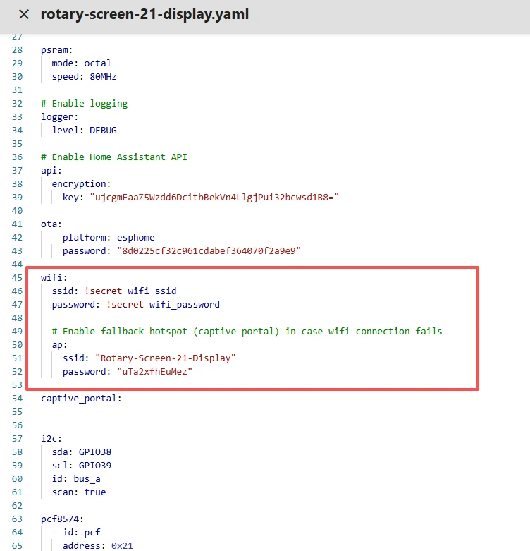
(7) wifi: + captive_portal: — Network Connection and Emergency AP
wifi:
  ssid: !secret wifi_ssid
  password: !secret wifi_password
  ap:
    ssid: "Rotary-Screen-21-Display"
    password: "uTa2xfhEuMez"
captive_portal:
This section configures Wi-Fi connectivity.
Under normal conditions, it connects to your home router; if it fails, it automatically enables a hotspot (AP), allowing you to reconnect using a mobile phone for reconfiguration.
captive_portal provides a web-based configuration interface to prevent the device from being bricked.
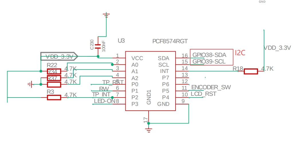
(8) I2C Control of the PCF8574 Expansion Chip
This section configures the I2C peripheral expansion and the core control pins of the display. It first initializes an I2C bus with GPIO38 as SDA and GPIO39 as SCL (id: bus_a) and enables bus scanning, used to communicate with the PCF8574 I/O expansion chip at address 0x21 — this chip is responsible for expanding critical pins such as touch reset, LCD power/reset, and encoder button.
On the CrowPanel 2.1inch-HMI ESP32 Rotary Display hardware, the PCF8574 expansion chip controls the following:
# P0: Touch reset (output)
# P2: Touch interrupt (input)
# P3: LCD power (output)
# P4: LCD reset (output)
# P5: Encoder button (input pull-up)
Therefore, I2C is required to control the PCF8574, thereby controlling the screen and touch functions.
(9) output: — “Actuators” for GPIO and PWM
output:
  - platform: ledc
    pin: 6
    id: bl_pwm
    frequency: 19531Hz

  - platform: gpio
    id: lcd_power
    pin:
      pcf8574: pcf
      number: 3
      mode:
        output: true
      inverted: false

  - platform: gpio
    id: display_reset
    pin:
      pcf8574: pcf
      number: 4
      mode:
        output: true
      inverted: true
Next, three types of output controls are defined: first, an LEDC PWM output via GPIO6 (frequency 19531Hz) for display backlight dimming; second, an LCD power control GPIO mapped to PCF8574 pin 3 (non-inverted output); third, a display reset control GPIO mapped to PCF8574 pin 4 (inverted output, matching the display’s “active-low reset” hardware logic).
Overall, the I2C expansion chip solves the problem of insufficient ESP32-S3 GPIO pins while precisely defining the driving methods for display power, reset, and backlight, providing a hardware control foundation.
(10) light: — Wrap PWM as a “Light”
light:
  - platform: monochromatic
    name: "LCD Backlight"
    output: bl_pwm
    id: display_backlight
    default_transition_length: 0s
    restore_mode: ALWAYS_ON
This section builds a monochromatic backlight control module based on the previously defined PWM output (bl_pwm). The core is to encapsulate the ESP32-S3 LEDC PWM output as a “LCD Backlight” light entity manageable by Home Assistant: specifying the monochromatic platform, linking it to the GPIO6 PWM output channel with ID bl_pwm, and assigning the unique identifier display_backlight.
default_transition_length: 0s ensures no transition delay during brightness adjustment (meeting the requirement for instant backlight response), and restore_mode: ALWAYS_ON ensures the backlight is enabled by default after reboot, preventing the issue of no backlight after power-on. It enables flexible brightness control while ensuring stability and ease of use.
(11) spi: — The High-Speed Highway for Screen Communication
This section configures the SPI bus between the ESP32-S3 and the 2.1-inch rotary display. It defines a minimal SPI bus (including only clock and master-out/slave-in lines): GPIO2 as the SPI clock (CLK) and GPIO1 as MOSI. The MISO pin is not configured because the display only requires the ESP32-S3 to send data to the ST7701S driver chip without receiving feedback. This SPI bus serves as the core communication channel for sending display commands and initialization sequences to the ST7701S, providing high-speed serial communication for configuration parameters and display data, matching the display’s “one-way data transmission” hardware characteristic.
(12) font: — Text Is Not Drawn Out of Thin Air
fines font resources.
When LVGL displays text, the font must be compiled into the firmware in advance.
You are using Google Fonts Roboto at 16 pixels in size (you can choose a suitable font size as needed).
(13) display: — The Actual Screen Driver
display:
  - platform: st7701s
    id: my_display
    update_interval: 50ms

    spi_mode: MODE3
    color_order: RGB
    invert_colors: false

    dimensions:
      width: 480
      height: 480

    #reset_pin:
    #  pcf8574: pcf
    #  number: 4

    cs_pin: 16
    de_pin: 40
    hsync_pin: 15
    vsync_pin: 7
    pclk_pin: 41
    data_pins:
      red: [46, 3, 8, 18, 17]
      green: [14, 13, 12, 11, 10, 9]
      blue: [5, 45, 48, 47, 21]

    hsync_front_porch: 20
    hsync_pulse_width: 10
    hsync_back_porch: 10
    vsync_front_porch: 8
    vsync_pulse_width: 10
    vsync_back_porch: 10
    show_test_card: true

    pclk_frequency: 18MHz
    pclk_inverted: true

    # https://github.com/moononournation/Arduino_GFX/blob/365a70bbca253966c6b89fcb649f11d52e6dbb9d/src/display/Arduino_RGB_Display.cpp
    init_sequence:
      - [0x01]
      - [0xFF, 0x77, 0x01, 0x00, 0x00, 0x10]

      - [0xCC, 0x10]
      - [0xCD, 0x08]

      - [0xB0, 0x02, 0x13, 0x1B, 0x0D, 0x10, 0x05, 0x08, 0x07, 0x07, 0x24, 0x04, 0x11, 0x0E, 0x2C, 0x33, 0x1D]
      - [0xB1, 0x05, 0x13, 0x1B, 0x0D, 0x11, 0x05, 0x08, 0x07, 0x07, 0x24, 0x04, 0x11, 0x0E, 0x2C, 0x33, 0x1D]

      - [0xFF, 0x77, 0x01, 0x00, 0x00, 0x11]

      - [0xB0, 0x5D]
      - [0xB1, 0x43]
      - [0xB2, 0x81]
      - [0xB3, 0x80]

      - [0xB5, 0x43]

      - [0xB7, 0x85]
      - [0xB8, 0x20]

      - [0xC1, 0x78]
      - [0xC2, 0x78]

      - [0xD0, 0x88]

      - [0xE0, 0x00, 0x00, 0x02]

      - [0xE1, 0x03, 0xA0, 0x00, 0x00, 0x04, 0xA0, 0x00, 0x00, 0x00, 0x20, 0x20]

      - [0xE2, 0x00, 0x00, 0x00, 0x00, 0x00, 0x00, 0x00, 0x00, 0x00, 0x00, 0x00, 0x00, 0x00]

      - [0xE3, 0x00, 0x00, 0x11, 0x00]

      - [0xE4, 0x22, 0x00]

      - [0xE5, 0x05, 0xEC, 0xA0, 0xA0, 0x07, 0xEE, 0xA0, 0xA0, 0x00, 0x00, 0x00, 0x00, 0x00, 0x00, 0x00, 0x00]

      - [0xE6, 0x00, 0x00, 0x11, 0x00]

      - [0xE7, 0x22, 0x00]

      - [0xE8, 0x06, 0xED, 0xA0, 0xA0, 0x08, 0xEF, 0xA0, 0xA0, 0x00, 0x00, 0x00, 0x00, 0x00, 0x00, 0x00, 0x00]

      - [0xEB, 0x00, 0x00, 0x40, 0x40, 0x00, 0x00, 0x00]

      - [0xED, 0xFF, 0xFF, 0xFF, 0xBA, 0x0A, 0xBF, 0x45, 0xFF, 0xFF, 0x54, 0xFB, 0xA0, 0xAB, 0xFF, 0xFF, 0xFF]

      - [0xEF, 0x10, 0x0D, 0x04, 0x08, 0x3F, 0x1F]

      - [0xFF, 0x77, 0x01, 0x00, 0x00, 0x13]
      - [0xEF, 0x08]

      - [0xFF, 0x77, 0x01, 0x00, 0x00, 0x00]

      - [0x36, 0x00]
      - [0x3A, 0x60]  # 0x70=RGB888, 0x60=RGB666, 0x50=RGB565

      - [0x11]
      - delay 100ms

      - [0x29]
      - delay 50ms
Driver Platform and Basic Identification
platform: st7701s: Specifies the display driver chip as ST7701S. ESPHome loads the dedicated driver logic for this chip, including command parsing, timing adaptation, and register configuration. This is the core foundation of the driver; selecting the wrong platform (such as st7789) will result in no display or garbled output.
id: my_display: Assigns a unique internal identifier to the display. Subsequent LVGL configuration and automation control (such as display.show) reference the screen through this ID.
update_interval: 50ms: Sets the screen refresh interval to 50ms (20Hz refresh rate), balancing smoothness and ESP32 computational load. At 480×480 resolution, excessively high refresh rates consume significant CPU and memory resources; 50ms is a compromise between smoothness and stability.
SPI Communication and Color Configuration
spi_mode: MODE3: SPI has four modes (MODE0–3), determined by clock polarity (CPOL) and phase (CPHA). MODE3 corresponds to “clock idle high, data sampled on falling edge,” which is required by the ST7701S chip. An incorrect mode will cause command/data transmission failure.
color_order: RGB: Specifies the pixel data channel order as red-green-blue, matching the screen’s color decoding logic. Setting BGR would result in incorrect color display (e.g., red appearing as blue).
invert_colors: false: Disables color inversion. If set to true, a negative-image effect would appear.
This is critical for parallel RGB displays and is divided into “control/synchronization pins” and “data pins”:
cs_pin: 16: SPI chip select pin, active low, used to lock communication to the ST7701S chip and avoid conflicts with other SPI peripherals.
de_pin: 40 (Data Enable): When high, the display receives pixel data; when low, it ignores it. It functions as the “switch” in parallel data transmission.
hsync_pin: 15 / vsync_pin: 7: Horizontal/vertical synchronization pins. HSYNC synchronizes the start/end of each line of pixels; VSYNC synchronizes the start/end of each frame, together defining the frame-line-pixel timing sequence.
pclk_pin: 41: Pixel clock pin, frequency 18MHz (pclk_frequency: 18MHz), determining pixel data transmission speed. 18MHz is a stable frequency supported by the ST7701S; too high causes data loss, too low causes display lag. pclk_inverted: true inverts the pixel clock to match the display’s sampling logic.
data_pins: Parallel RGB data pins, allocated as red (5 lines), green (6 lines), and blue (5 lines), totaling 16 bits (5+6+5), corresponding to RGB666/565 formats (0x60=RGB666 in the comment). These pins must exactly match hardware wiring; even a single incorrect pin causes stripes, color shifts, or no display.
Synchronization Timing Parameters
These parameters are calibrated by the panel manufacturer to match the “blanking period” timing:
front_porch: After the sync signal is triggered, delay a number of pixel clocks before data transmission begins (front blanking).
pulse_width: Duration of the sync signal (pulse width).
back_porch: After data transmission ends, delay a number of pixel clocks before ending the sync signal (back blanking).
Example: hsync_front_porch: 20 means after HSYNC is triggered, wait 20 PCLK cycles before transmitting pixel data for that line. Incorrect timing causes offset, tearing, or missing edges.
Debug and Initialization Configuration
show_test_card: true: Enables test card display. After startup, the screen shows a colored checkerboard/gradient pattern to quickly verify driver correctness (if the test card displays normally, hardware pins and timing are correctly configured).
init_sequence: The initialization command sequence of the ST7701S chip, which is the core of the driver — including reset (0x01), power management, gamma correction, color format (0x3A=0x60 for RGB666), display on (0x29), and numerous register configurations. It fully replicates the Elecrow official reference code to ensure proper operation for this rotary display. The commented reset_pin is omitted because hardware reset was already performed via PCF8574 in on_boot to avoid duplicate reset.
(14) lvgl: — The “Brain” of the Graphical Interface
lvgl:
  displays:
    - my_display
  widgets:
    - label:
        align: CENTER
        id: lbl_title
        text_font: montserrat_28
        text: "Hello World!"
This section configures the graphical interface based on the LVGL graphics library. The core is binding LVGL to the previously defined ST7701S display (ID: my_display), directing LVGL’s rendering output to the 480×480 rotary screen.
A basic text label widget is created, aligned to the center of the screen (CENTER), assigned the unique ID lbl_title, using the montserrat_28 font (which must be predefined), and displaying the text “Hello World!”. This is the core configuration that builds a visual interface on top of hardware driving, representing the key transition from “the screen lights up” to “the screen displays custom content,” and is the foundational LVGL application in ESPHome.
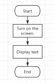
5. Code Logic Flowchart
6. Flashing Steps
Next, we will teach you how to use ESPHome to write code for the first time, including the overall workflow. Please follow us step by step.
Here we emphasize again:
The following devices need to be on the same LAN:
① Your computer
② CrowPanel HMI ESP32 Rotary Display
③ Raspberry Pi with the Home Assistant system
In this project, the Raspberry Pi with the Home Assistant system acts as the server, so every time you access the IP address of the Raspberry Pi with the Home Assistant system, you are entering Home Assistant. Only after entering this page can you perform the following operations.
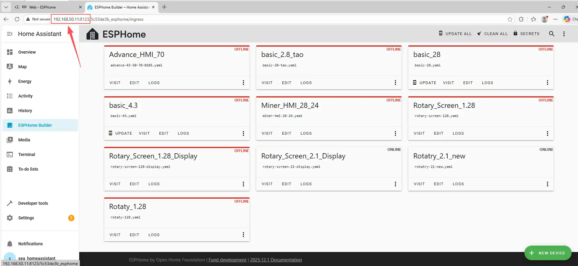
The following steps assume you have completed the installation in the previous lesson and reached the ESPHome main page.
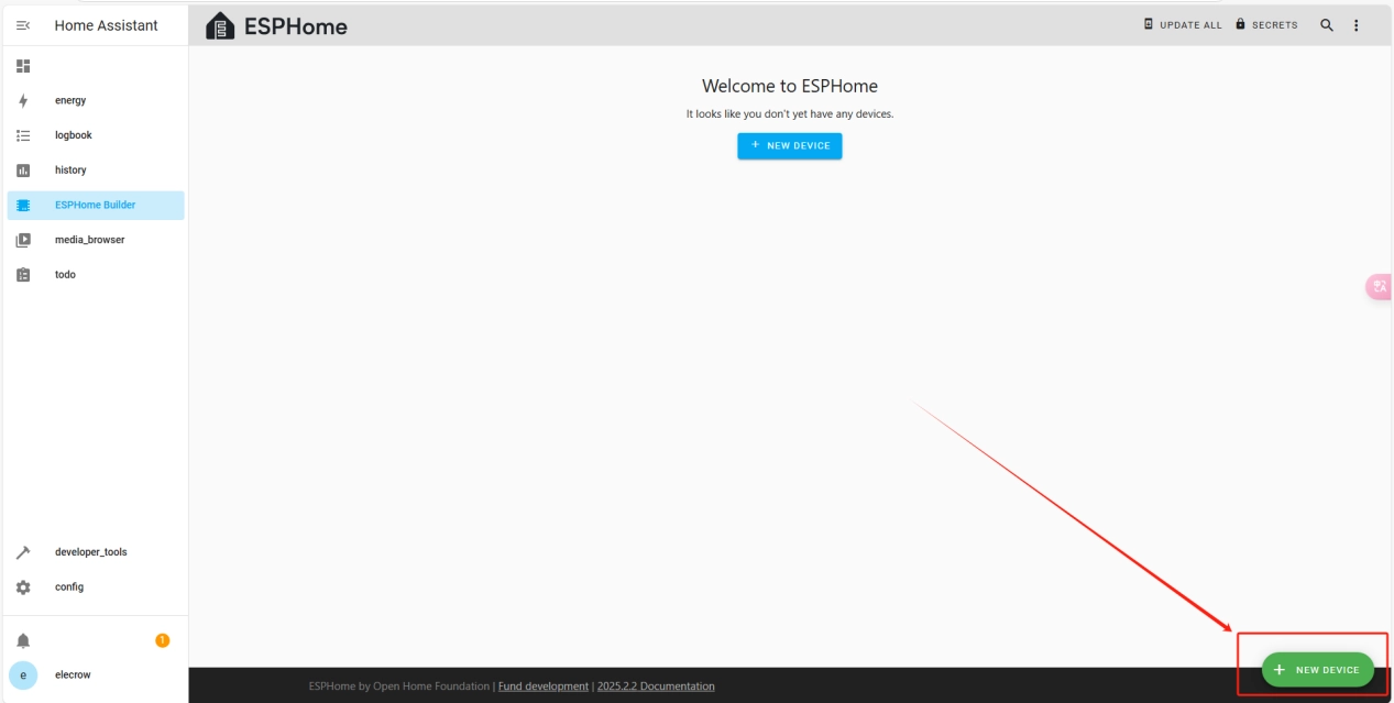
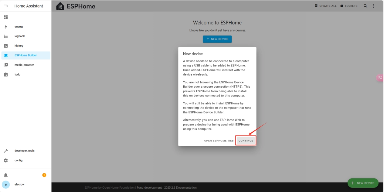
Once the installation is complete, we can start adding devices. Click on + New Device -> Continue.
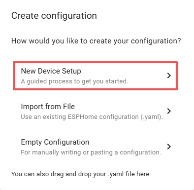
Click “New Device Setup”.
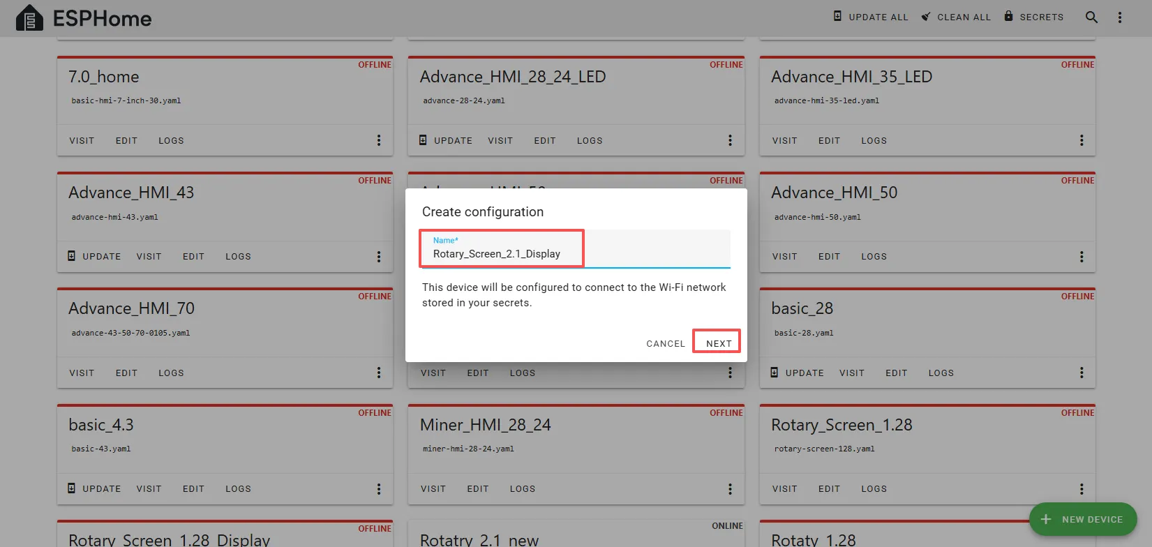
Enter a name and click Next.
(You can use any custom name. Do not include strange symbols such as @, #, etc.)
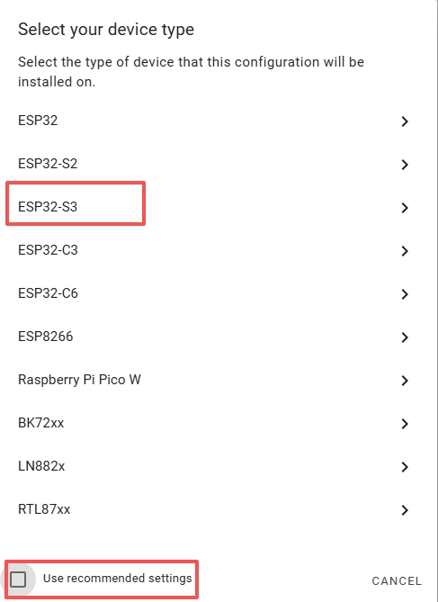
Here, do not check “Use recommended settings.”
Select the main chip of the CrowPanel 2.1inch-HMI ESP32 Rotary Display, ESP32-S3.
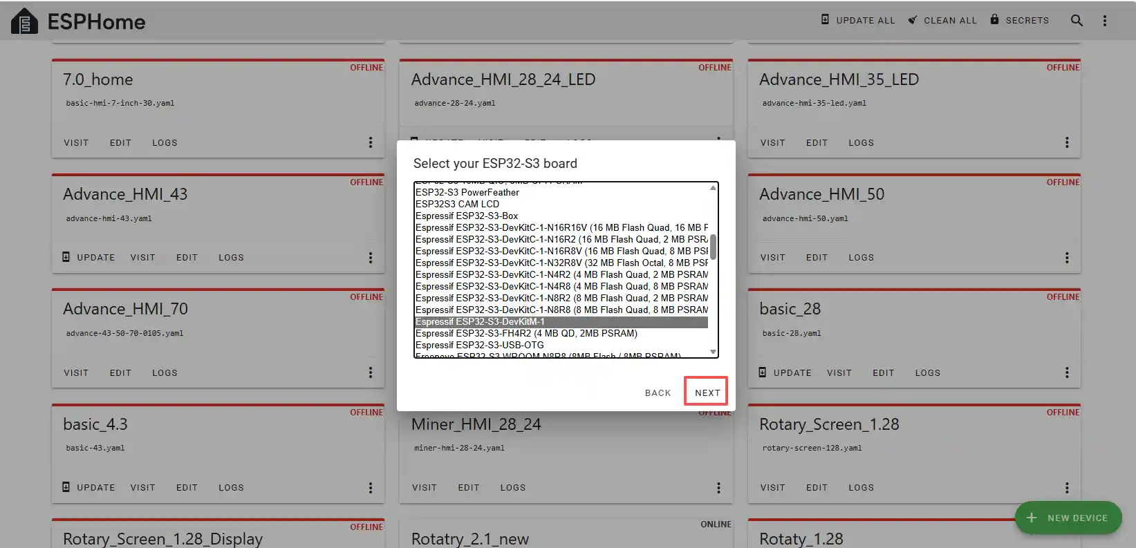
Next, choose any option (since we will replace it in the code later).
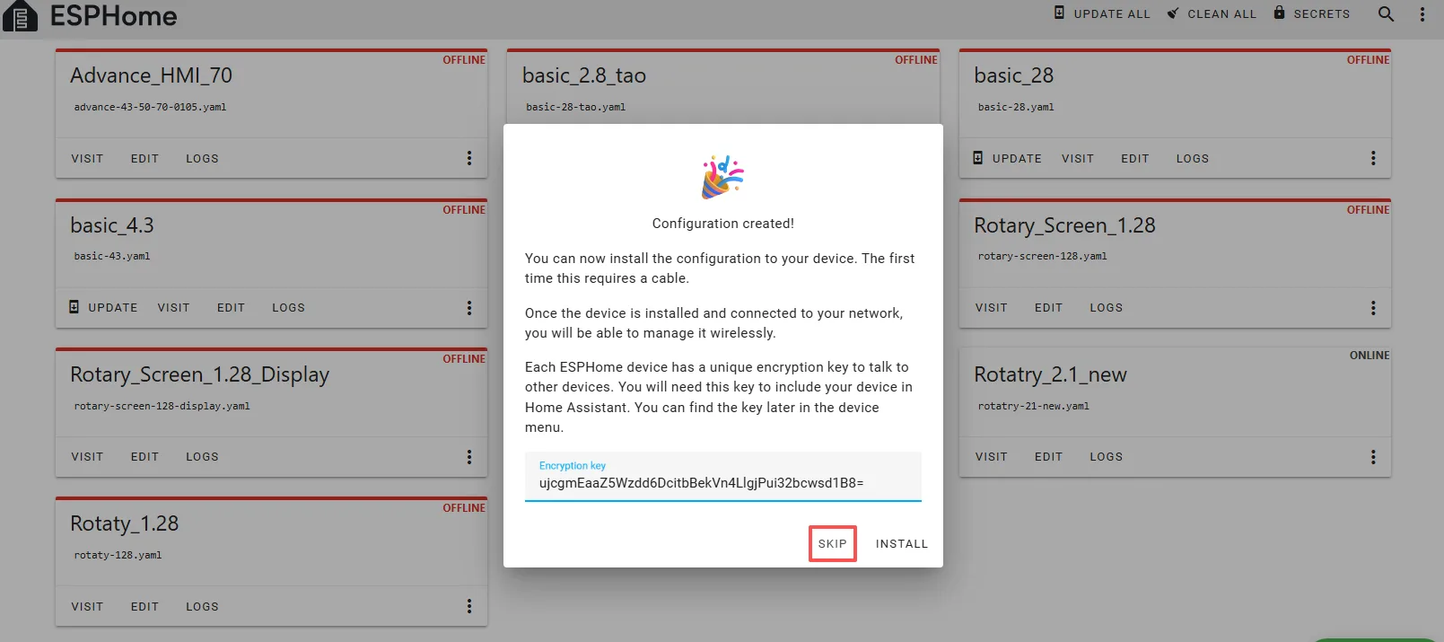
Here, click “SKIP”.
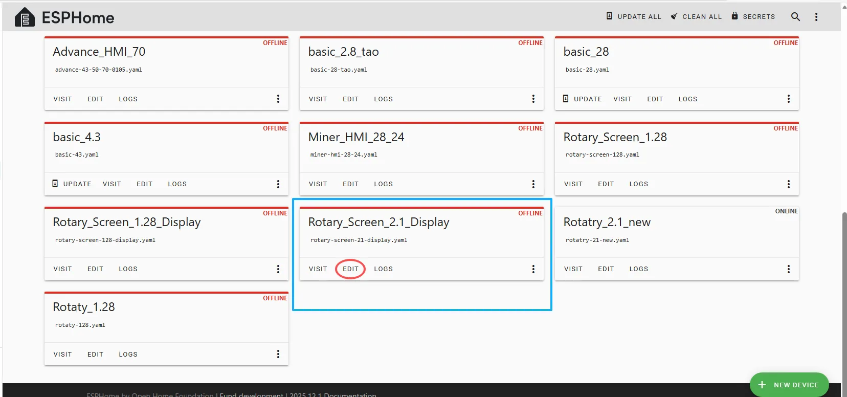
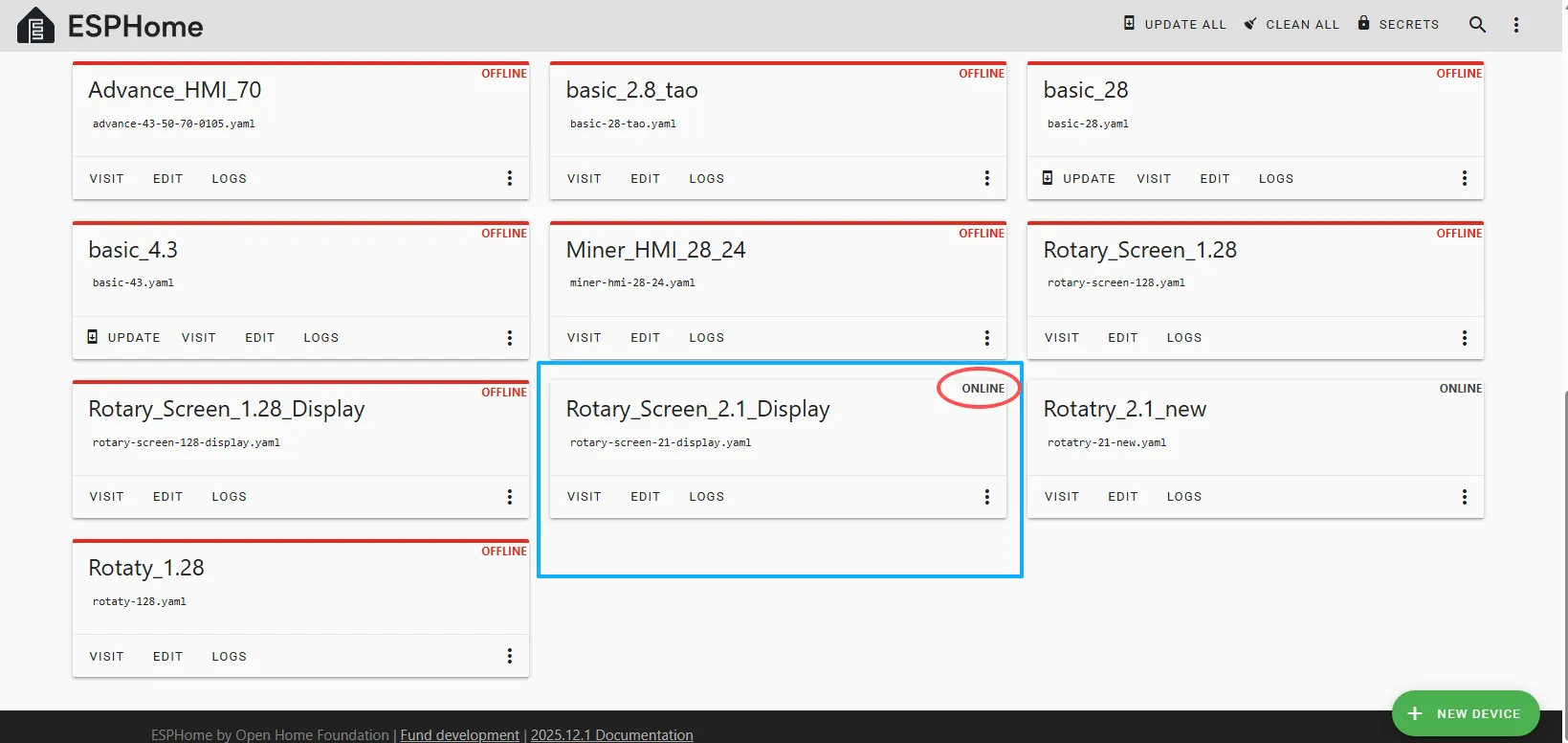
Then return to the main interface, find the Rotary_Screen_2.1_Display you just created, click “EDIT,” and enter the code editor.
This code is automatically generated based on the previous steps. Next, we will replace parts of it to optimize performance.
Automatically generated code:
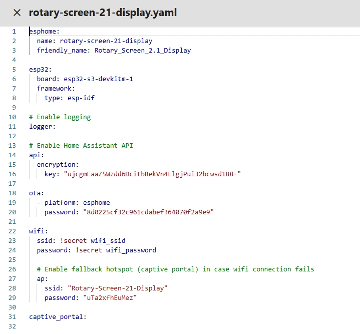
This is the complete code. You can click the code link below to obtain it.
Next, replace the relevant content in esphome and esp32 as needed, and add the “PSRAM” section.
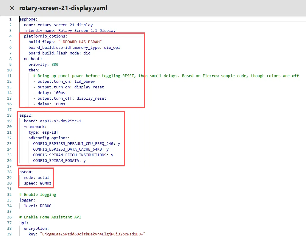
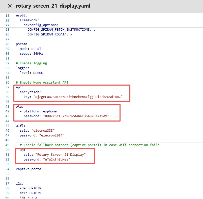
Then, based on your existing code, follow the format shown in the figure to add or replace these codes.
(Other configurations remain unchanged)
Remember to replace your own Wi-Fi name and password.
Note: This Wi-Fi must be on the same local network as your computer and Raspberry Pi.
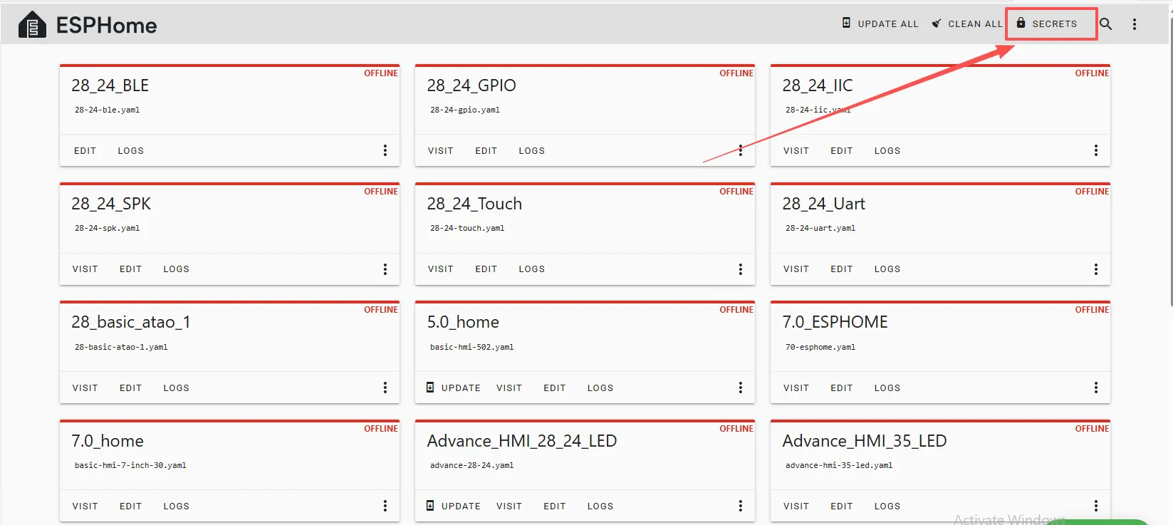
Here, the Wi-Fi account and password are set on the ESPHome main page.
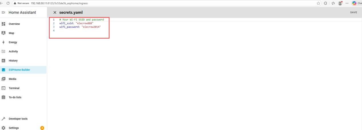
Therefore, you can write it in the code like this, meaning we are using the Wi-Fi named “elecrow888.”
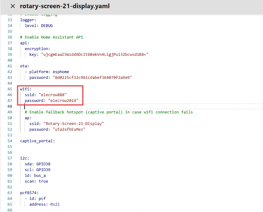
Of course, you can also directly write the Wi-Fi account and password in detail in the code.
Note: These items are unique to the device you created and cannot be the same as mine. Keep your originally generated ones.
You can copy the other functional code from mine.
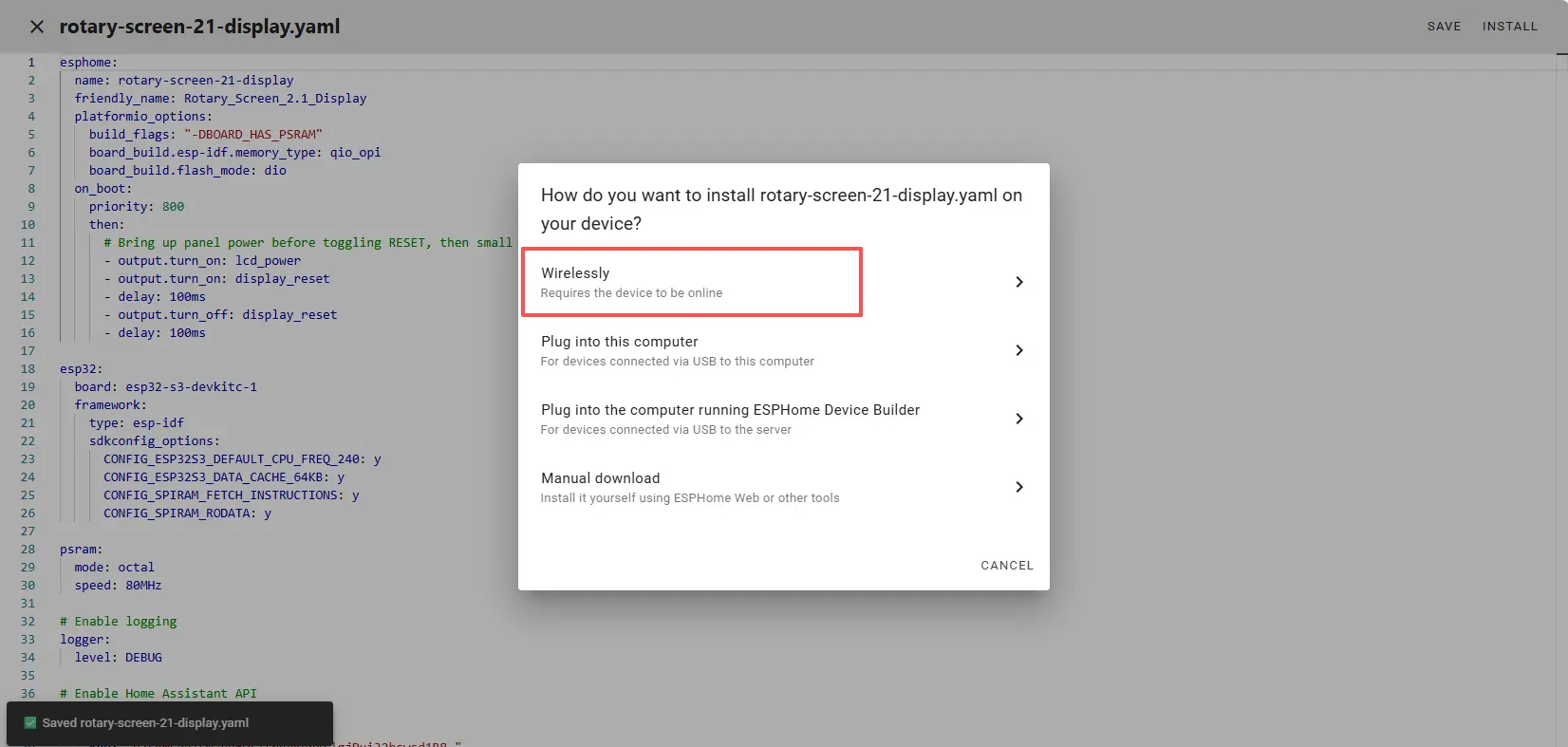
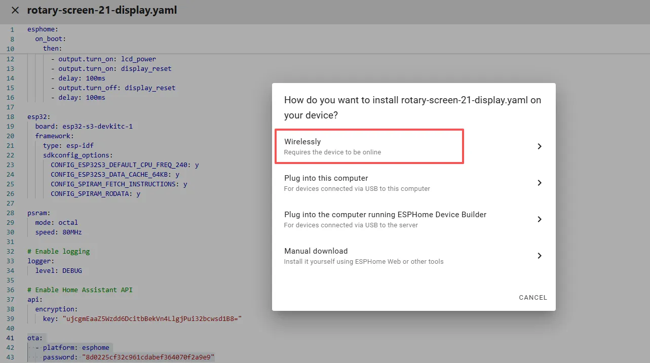
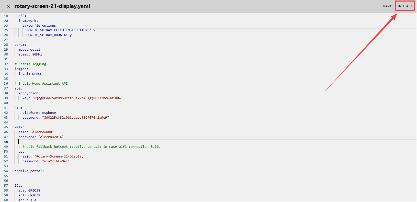
Once the code replacement is complete, click “INSTALL” in the top right corner.
Select “Manual download”.
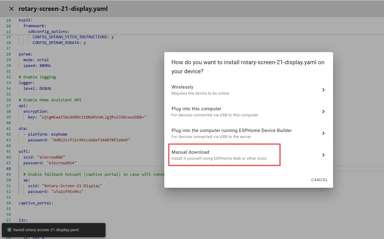
Wait a few minutes until the installation is complete.
Then select “Factory format”.
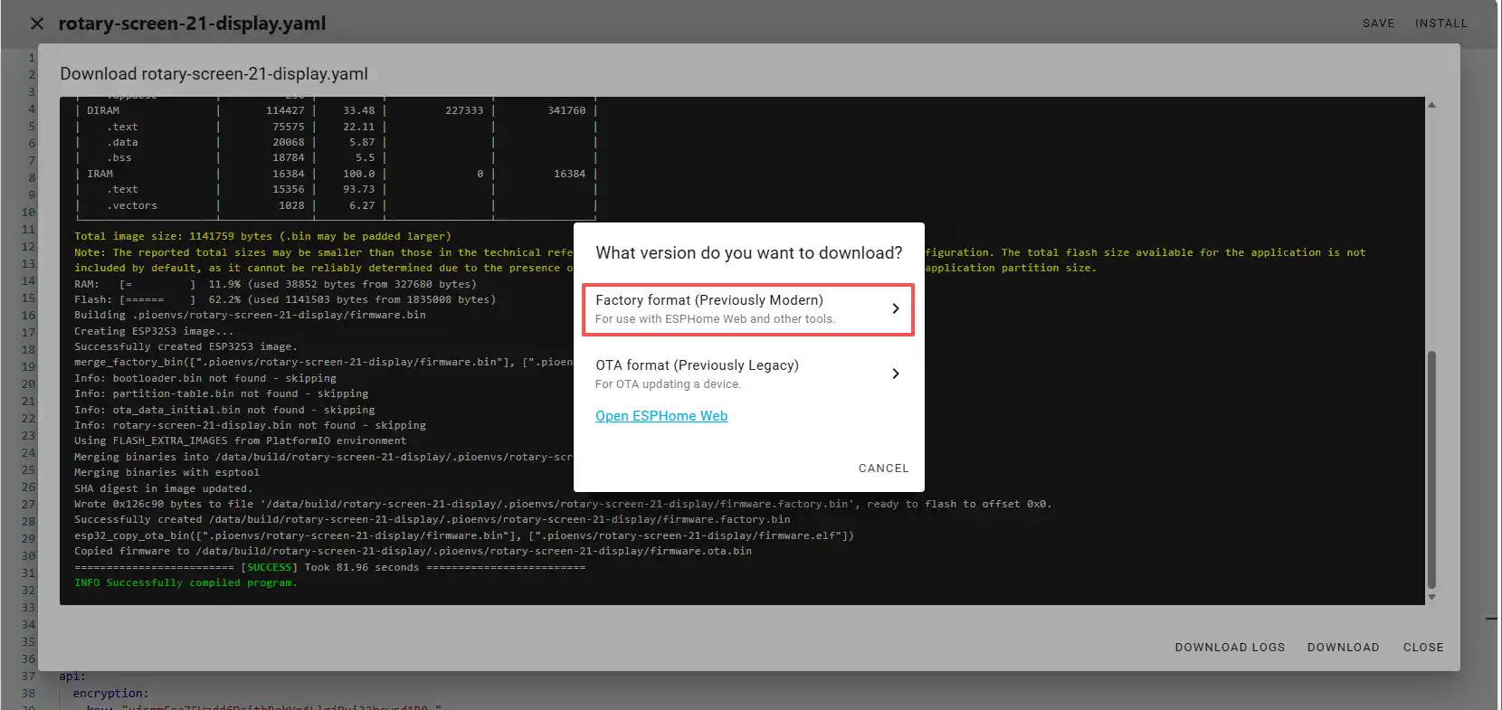
Once the download is complete, you will see the .bin file.
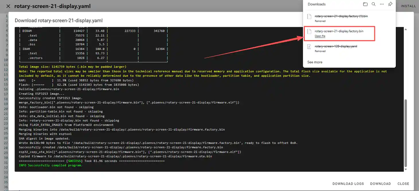
Remember the path of this .bin file.
Open the following website: https://web.esphome.io/?dashboard_wizard
After opening this website, you will arrive at this interface:
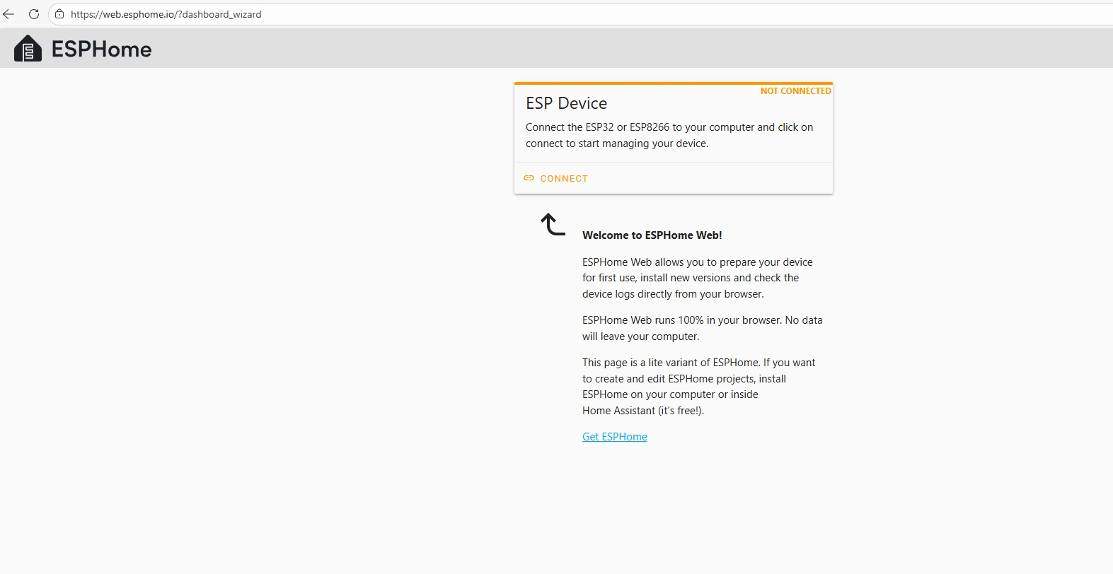
Next, we will flash this .bin file into the CrowPanel 2.1inch-HMI ESP32 Rotary Display.
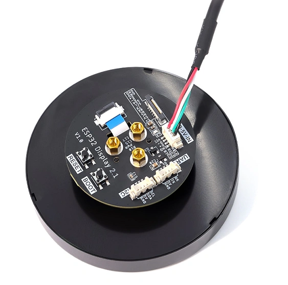
Connect the CrowPanel 2.1inch-HMI ESP32 Rotary Display to your computer.
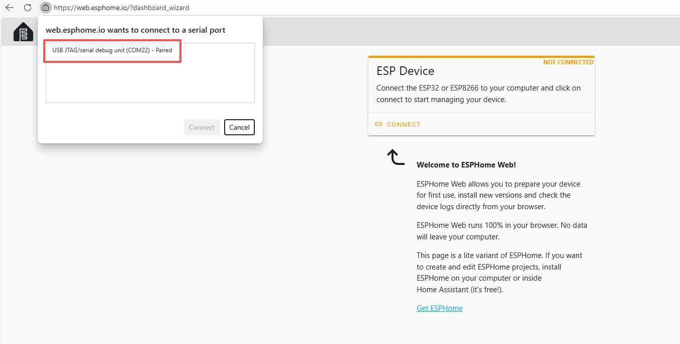
Click “Connect”.
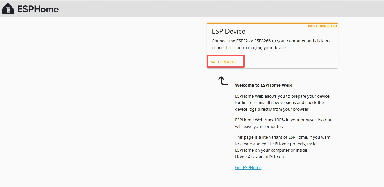
Select the COM port and connect it.
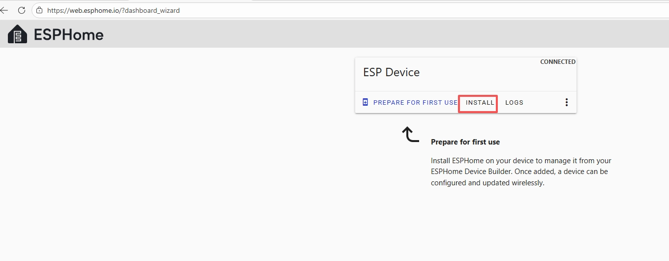
After connecting the CrowPanel 2.1inch-HMI ESP32 Rotary Display, click “Install”.
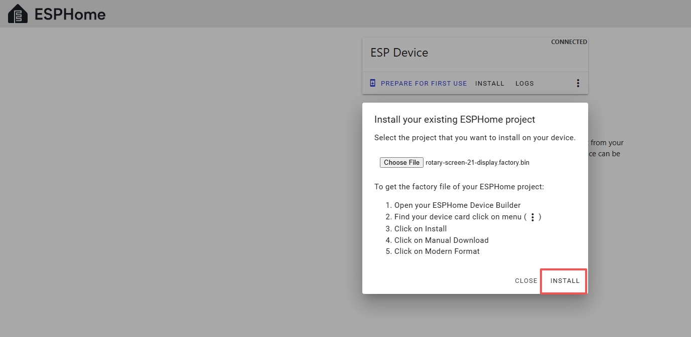
Add the .bin file you just downloaded, then click “Install”.
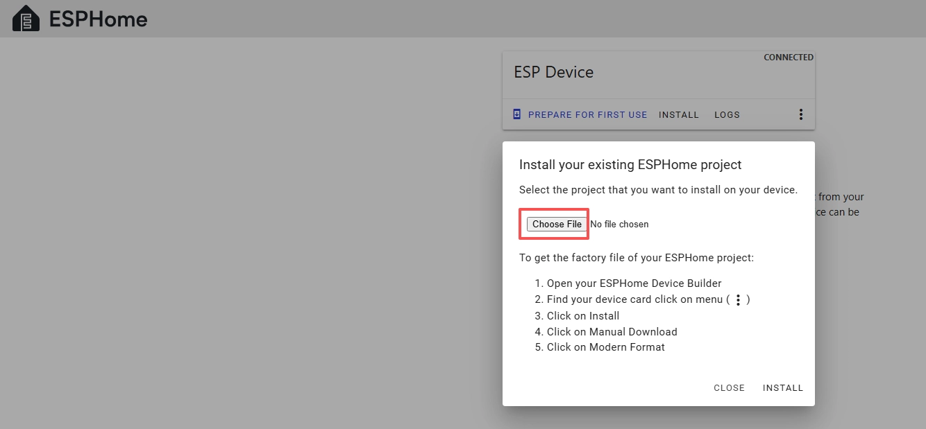
Then select the .bin file you just downloaded.
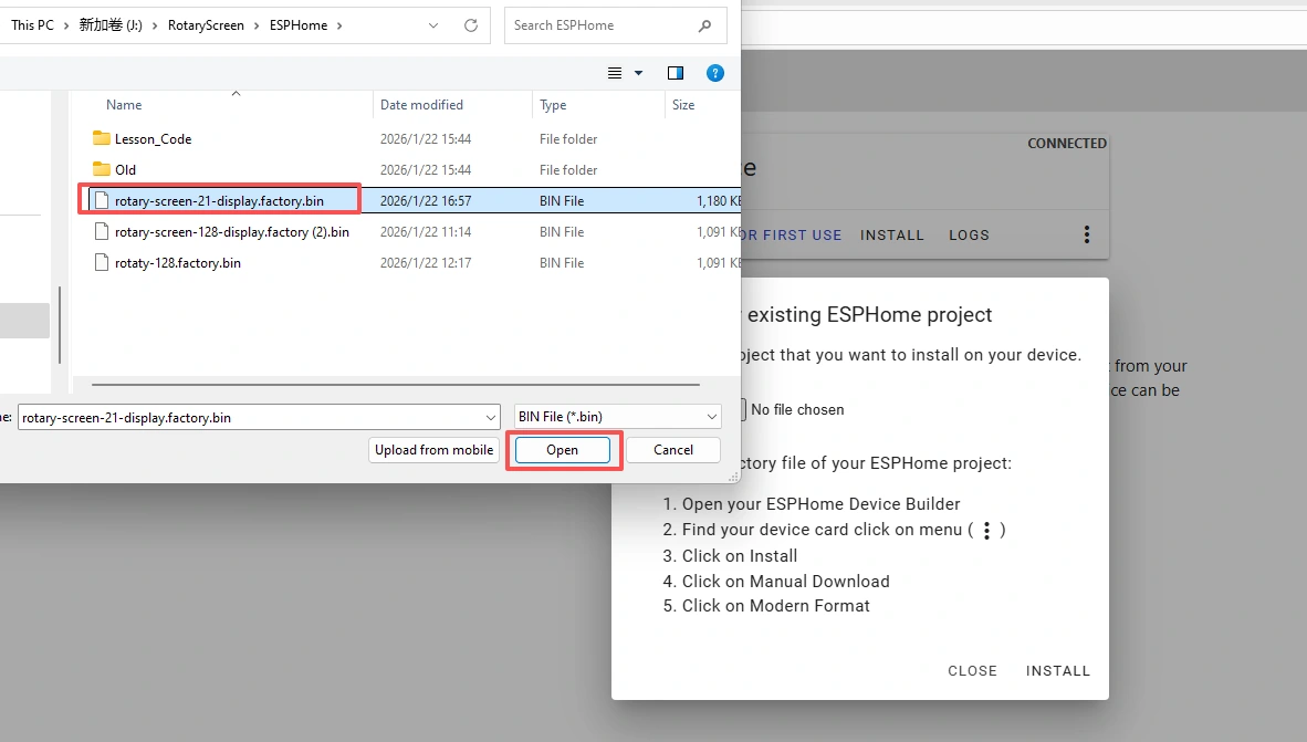
Click “INSTALL”.
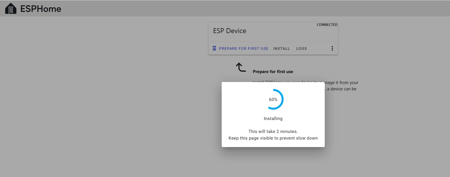
Wait a few minutes.
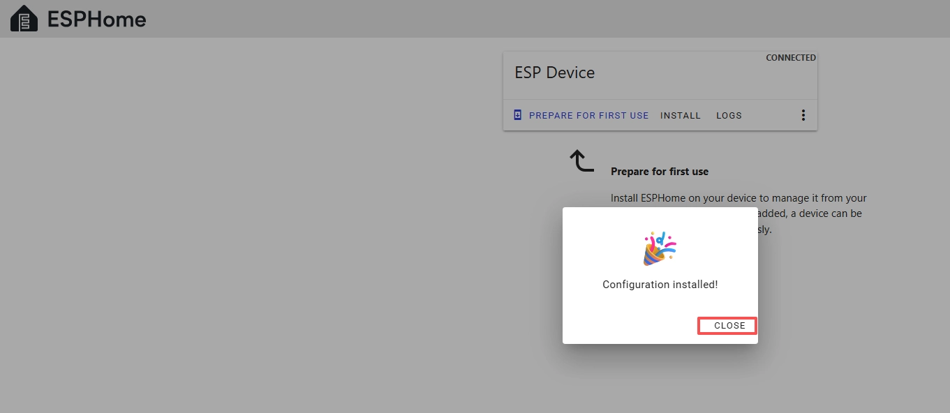
After the installation is complete, click “Close”.
After successfully flashing the .bin file, return to the ESPHome page in Home Assistant.
Press the RESET button on the CrowPanel 2.1inch-HMI ESP32 Rotary Display.

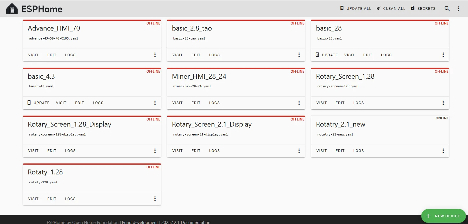
Restart the ESP32 display, and you should see the device you created earlier show as ONLINE in the top right corner.
And if you have also added the functional code we provided, you will see “Hello World!” displayed on the screen.

After it shows ONLINE here, if you make any modifications to the code later and want to upload it again, you can use the wireless upload method, which will be much more convenient.