ESP32 P4 SquareLine LVGL 10.1inch
SquareLine Studio User Guide
1. Introduction
In Lesson 9 of ESP-IDF, we manually wrote LVGL code to design the LVGL interface and controls to manage turning the LED on and off. In this lesson, based on the functionality implemented in Lesson 9 of ESP-IDF, we will use the SquareLine Studio platform to generate the LVGL interface and controls, enabling a more visually appealing and convenient interface to control the LED. Once you have mastered this method, you can also use it to design more interesting interfaces.
Squareline Tutorial Video:
Squareline Tutorial for CrowPanel Advanced ESP32 P4 HMI AI Display Series
2. Operation Effect Diagram
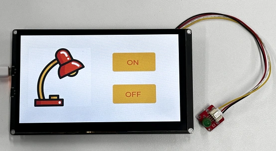
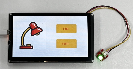
After completing the design on the SquareLine Studio platform, integrating the exported UI files into the project, and successfully uploading them, you will see this beautifully designed interface.

When you click the ON button on the screen, you will be able to turn on the LED.

When you click the OFF button on the screen, you will be able to turn off the LED.

3. Introduce LVGL
LVGL (LittlevGL) is an open-source, lightweight, high-performance embedded graphics library designed specifically for devices with limited resources. It supports multi-platform porting, provides rich controls, animations, touch support, and highly customizable styles, suitable for fields such as smart homes, industrial equipment, medical instruments, etc. LVGL is centered around modular design and can run on bare metal or operating systems, accelerating GUI development through powerful community support and tools such as SquareLine Studio.
SquareLine Studio is a next-generation user interface (UI) solution for individuals and professionals, allowing users to quickly and easily design and develop aesthetically pleasing UIs for embedded devices. This software provides integrated design, prototyping, and development capabilities, supporting the export of platform-independent C or MicroPython code for LVGL (Lightweight Graphics Library), which can be compiled and run on any vendor's device.
4. SquareLine Studio User Guide
4.1 Installation Guide
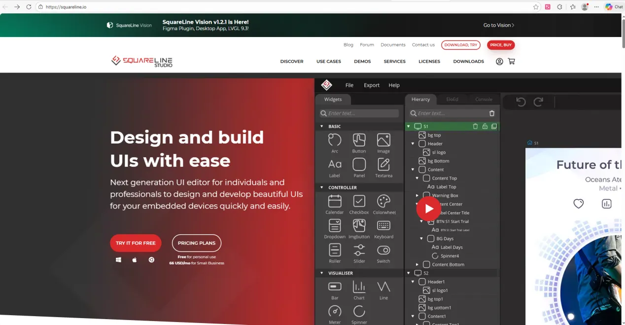
Enter https://squareline.io/ to download the SquareLine installation file.
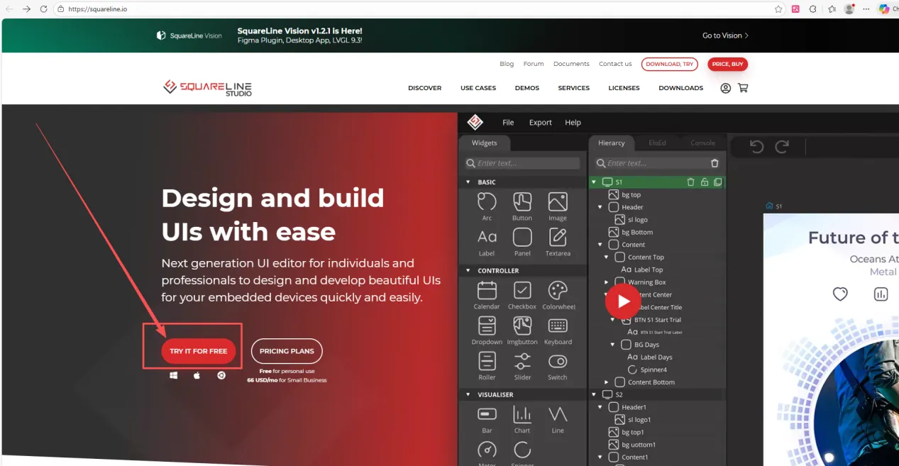
Then go to this download page.
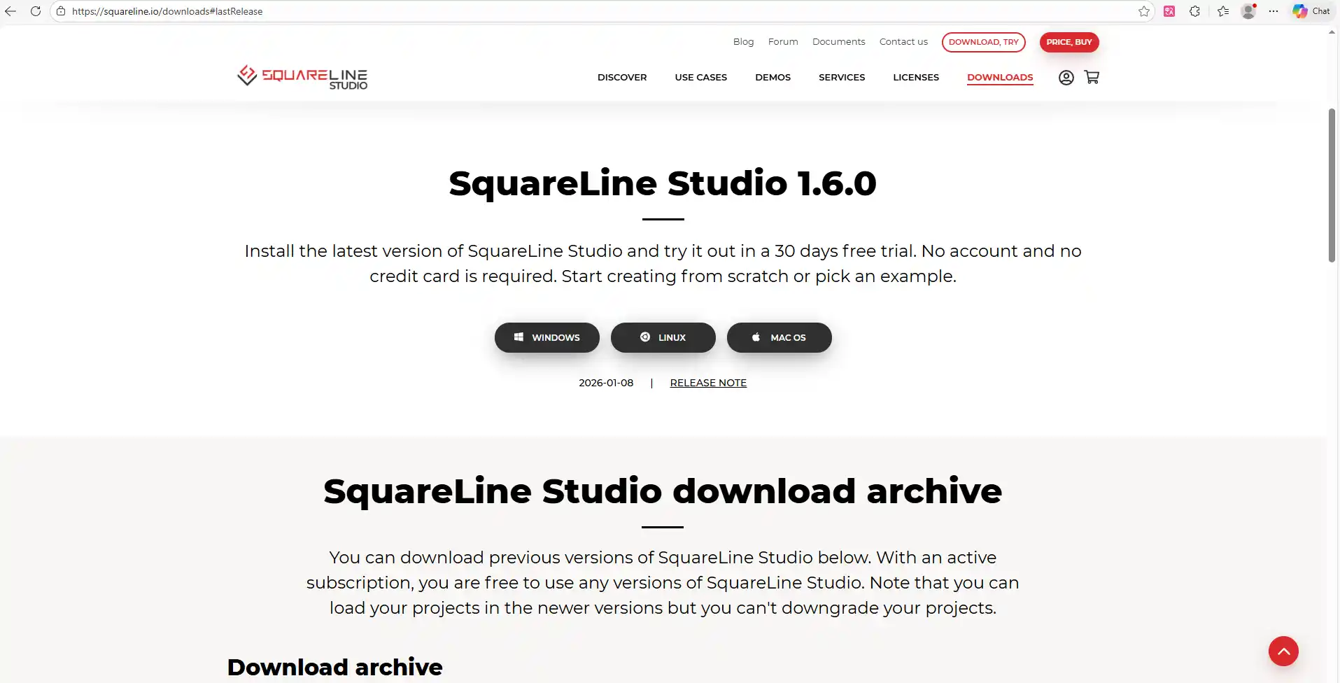
Please note that the SquareLine Studio version we are using is 1.5.1.
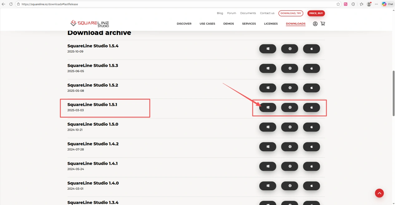
Scroll down and select version 1.5.1 for download.
(Choose the version according to your operating system. Here I am using the Windows system.)
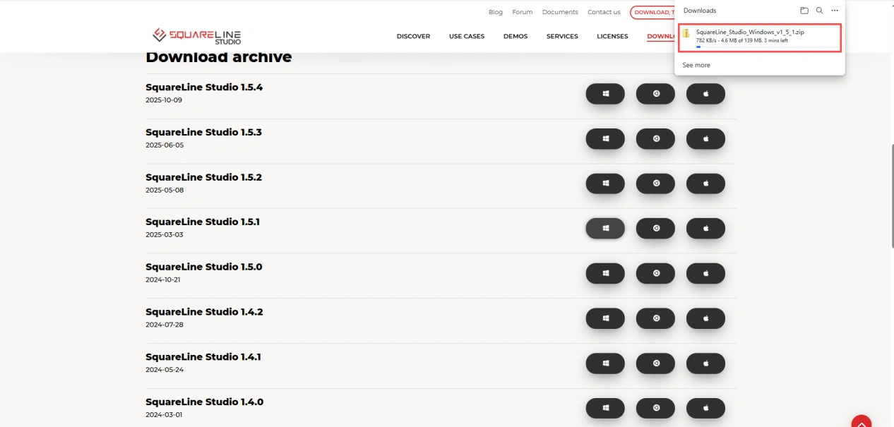
Wait for the download to complete.
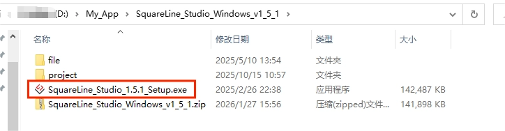
Place the downloaded compressed file in a folder you are familiar with and extract it to obtain the .exe file.
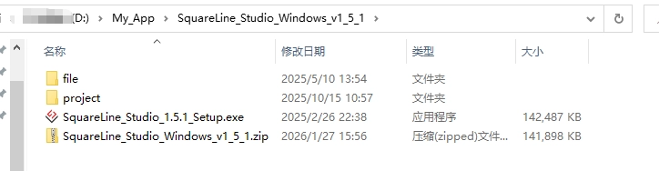
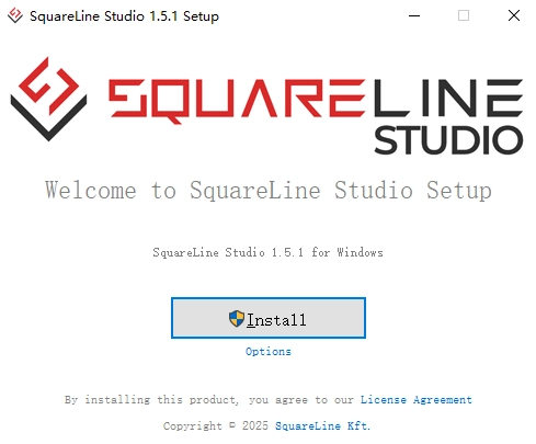
Double-click it.
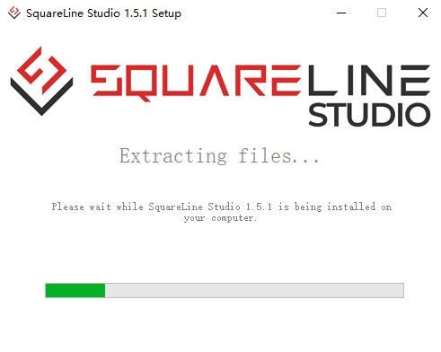
Proceed with the installation.
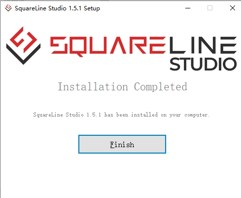
Wait for the installation to complete.
Installation completed.
Now you can see the software on your desktop.
Double-click to open it.
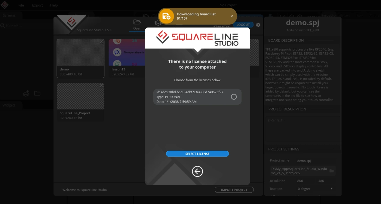
Then complete identity authentication and log in.
4.2 Designing the Interface in SquareLine Studio
After logging in successfully, you will arrive at this interface. Follow the steps in sequence to make your selections. Finally, choose this project as the template to design the interface used on the ESP32-P4 in this lesson.
(Here we are using LVGL version 9.2.2. Please pay attention to your selection in step 2.)
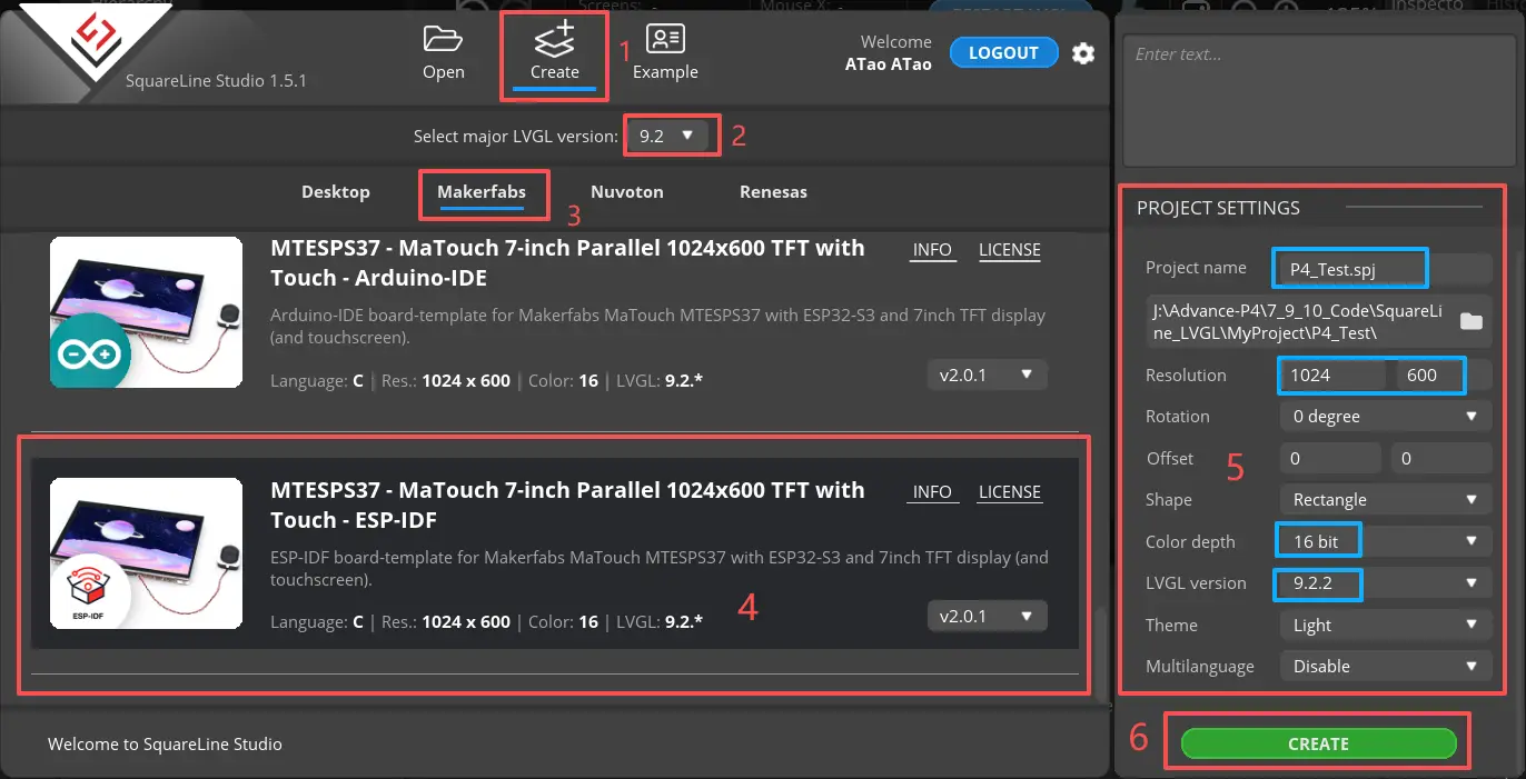
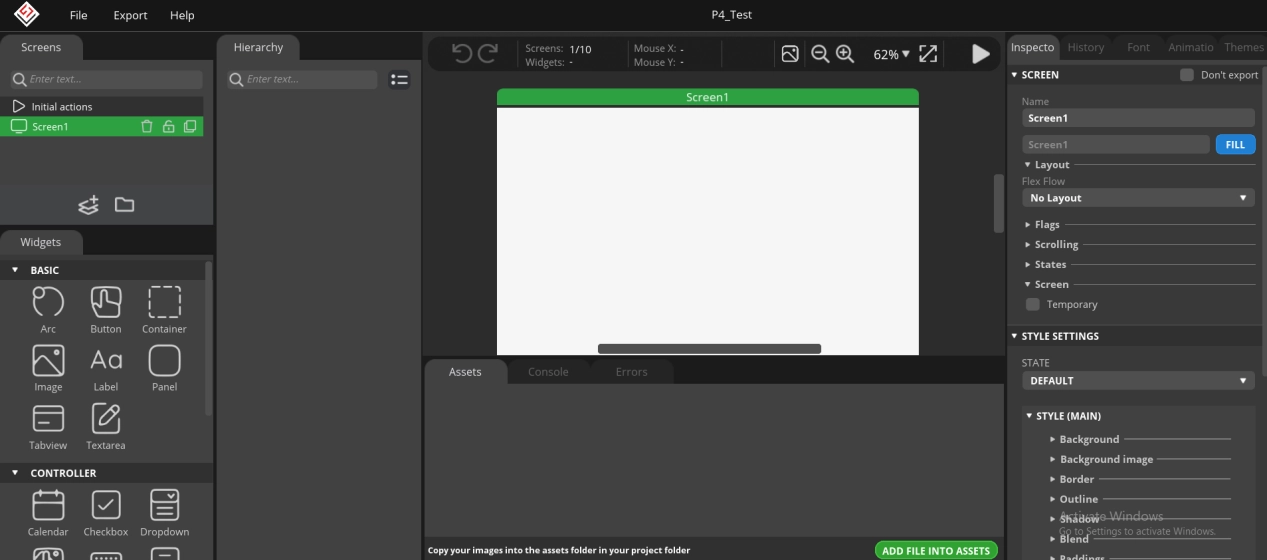
After completing the above six steps, click Create to enter this design interface.
Before starting, click the link below to download the image resources we provide.
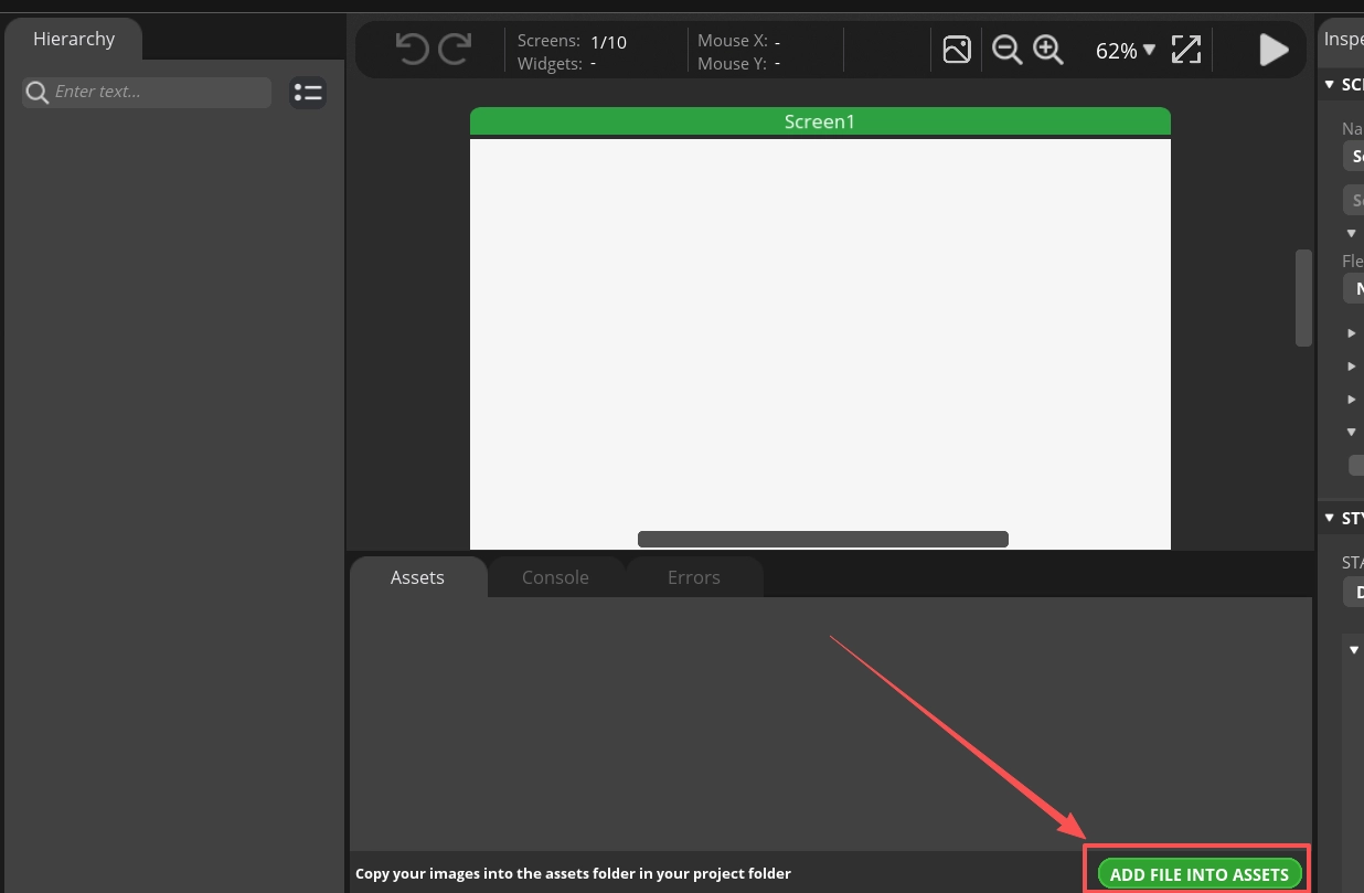
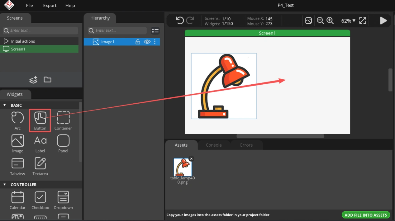
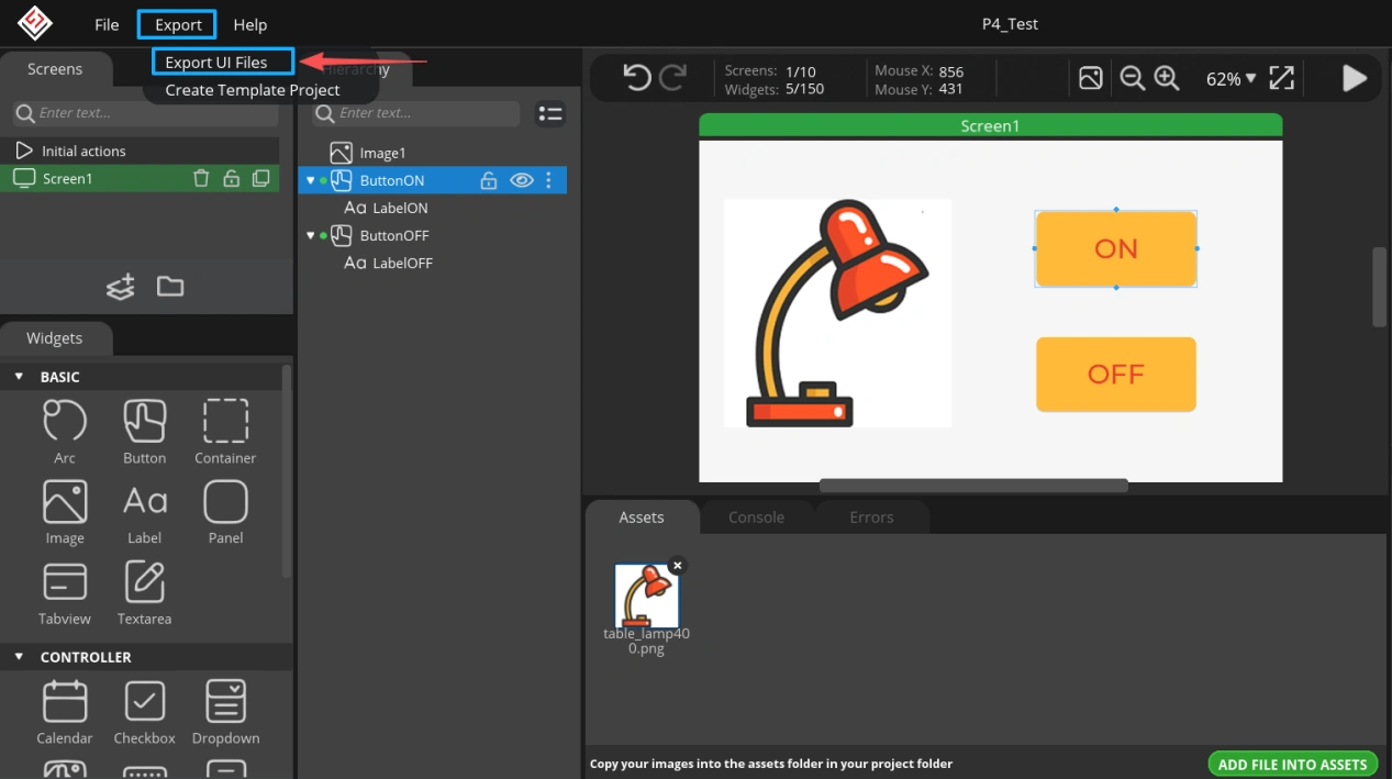
Click “ADD FILE INTO ASSETS” at the bottom of the design interface to import the provided resources.
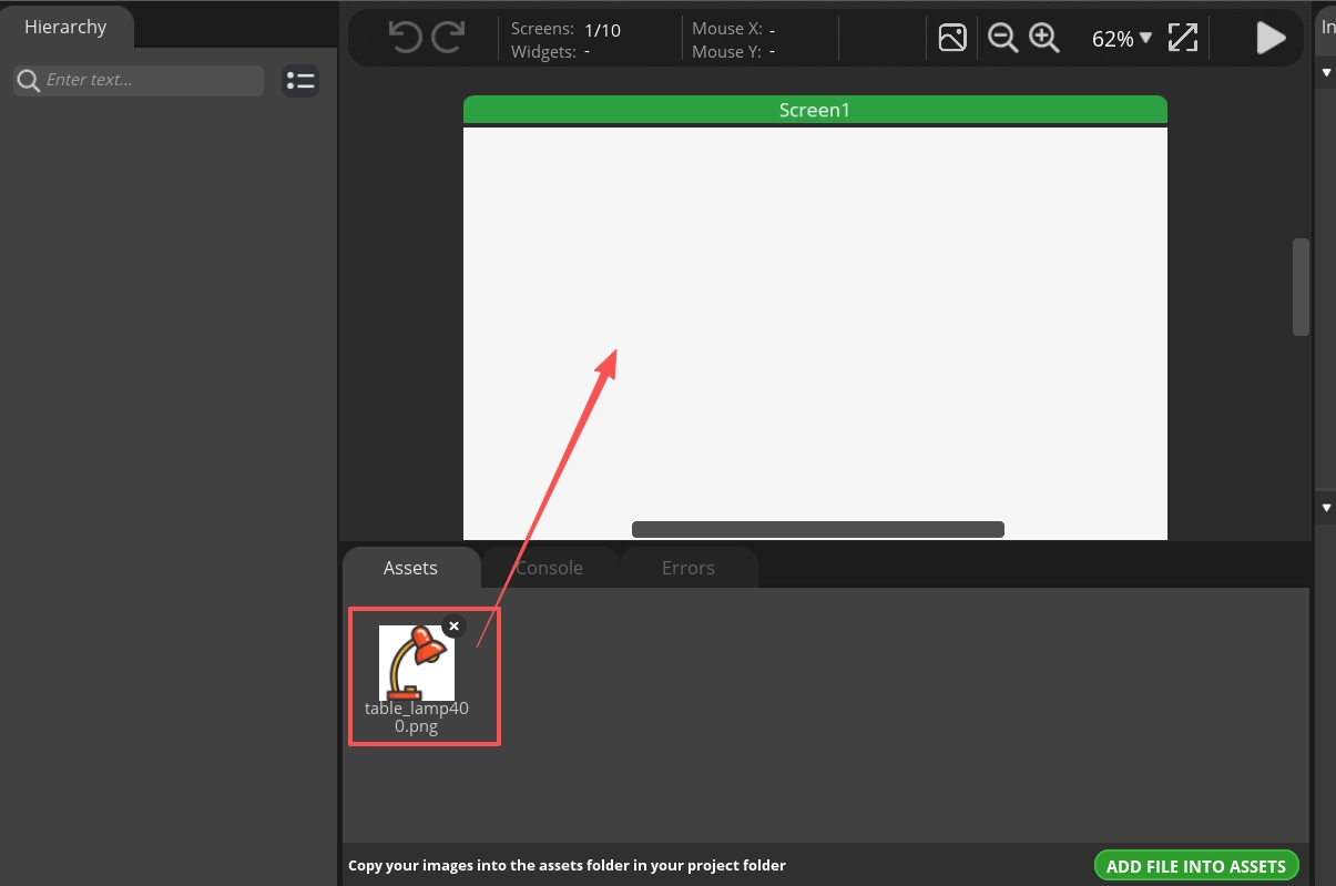
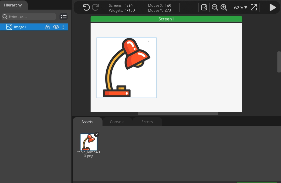
Then drag the imported resources into the design interface.
Next, we will design the buttons.
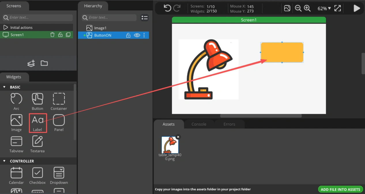
In the “BASIC” section on the left, find “Button” and drag it into the design interface.
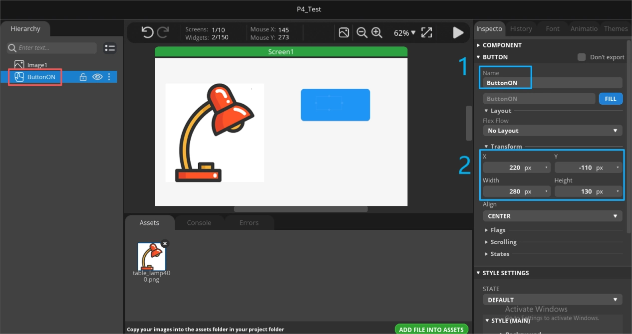
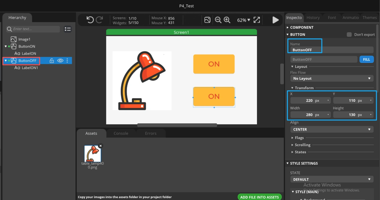
Then, in the design panel on the right, customize the button. I will use an example here; you can design your preferred style.
Step one: Rename it to a name that clearly indicates its function at a glance.
Step two: Set the button’s length and width, as well as its position within the design interface.
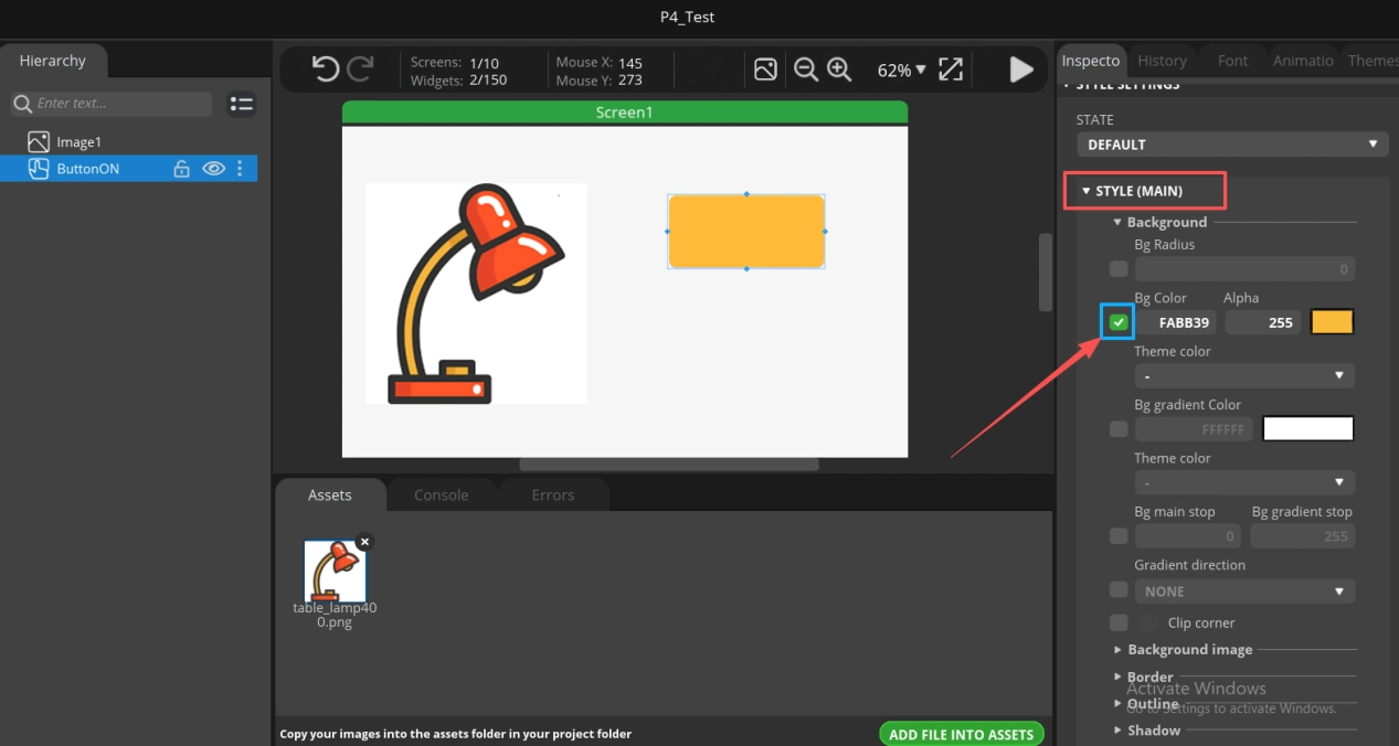
Step three: Customize the button style, such as the button color, background, border, etc.
(Here I only customized the button color.)
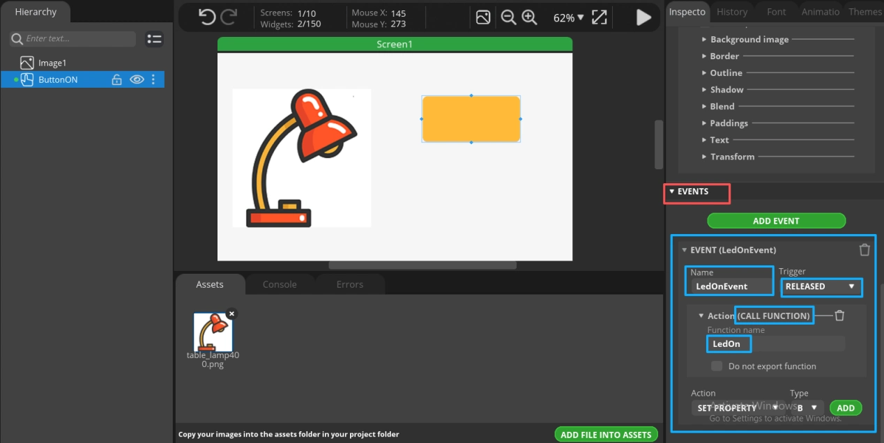
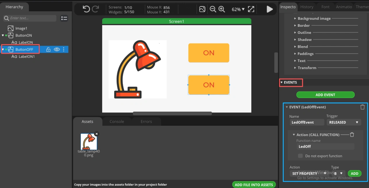
Step four: Since we need to turn on the LED after clicking the button, we add an event to the button here. Later, we will edit the code to control the LED connected to the Advance-P4.
(It is recommended that both the event and function names be clearly identifiable.)
Now that the button design is complete, let’s add a label to indicate illumination more clearly.
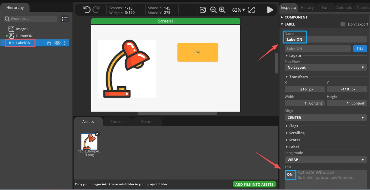
Drag the “Label” into the design interface.
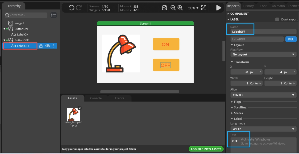
Similarly, customize the label by renaming it and editing the text.
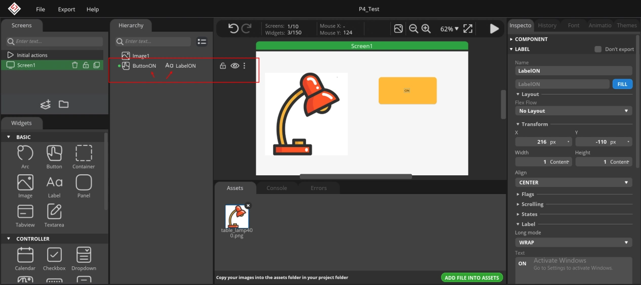
Next, bind the label to the button.
Drag the label onto the button to bind them together.
Set the label position to 0 so that it is centered within the button.
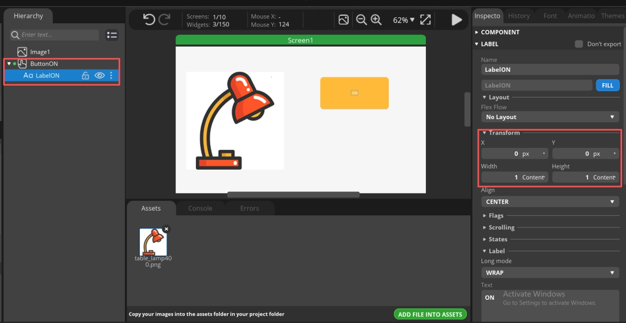
Now the label “ON” looks small. Let’s adjust its size and color together.
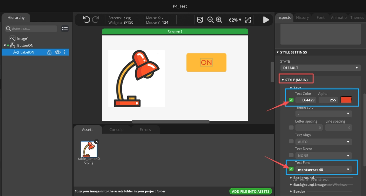
That looks much better now.
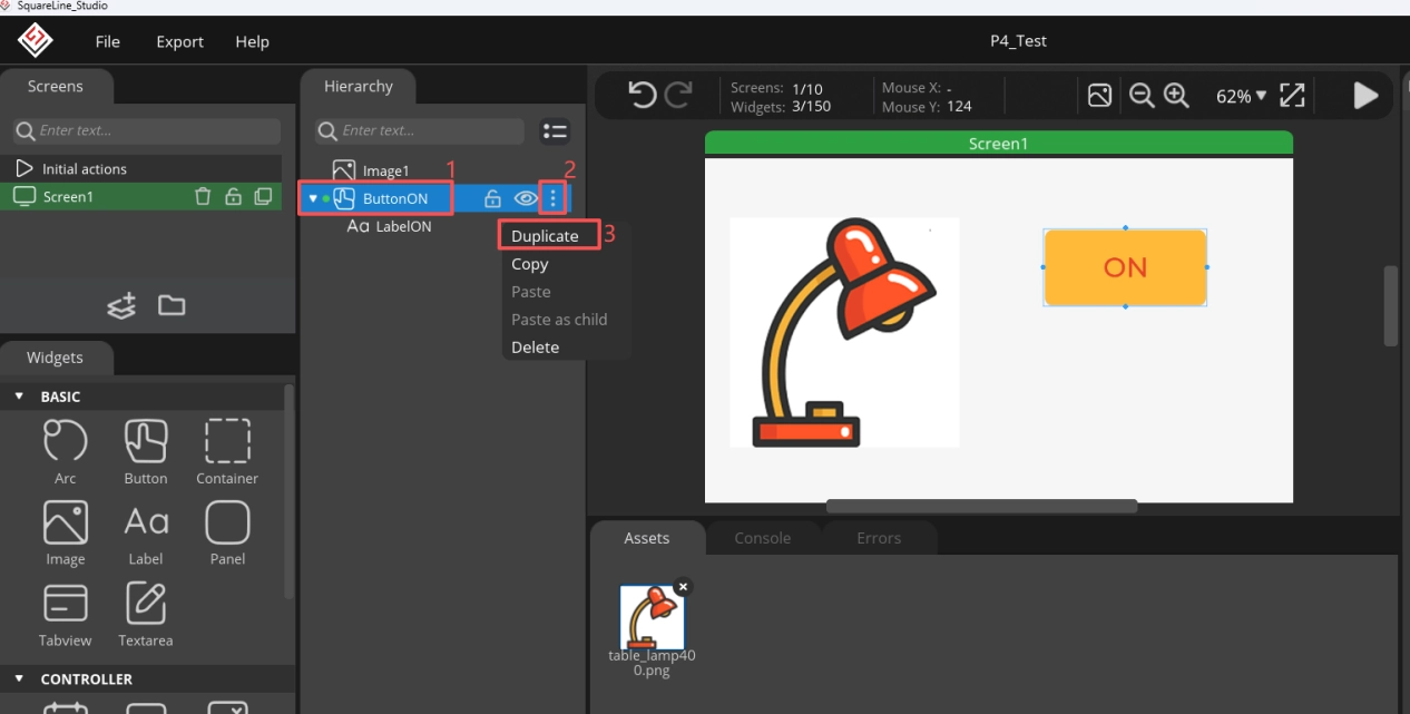
Now that the ON button is ready, designing the OFF button becomes easy. Here, we directly duplicate the ON button design.
Now you can see the second button.
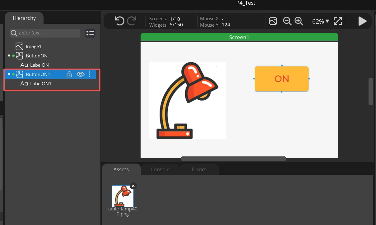
The duplicated button overlaps with the original one. Drag it to reveal the copied button.
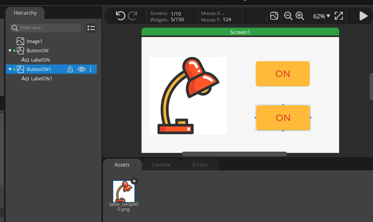
Now we only need to make the necessary modifications based on the original.
4.3 Export the UI Files
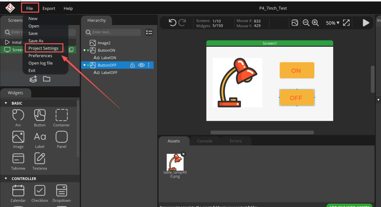
At this point, the complete UI interface design is finished. Next, we will export this UI interface file.
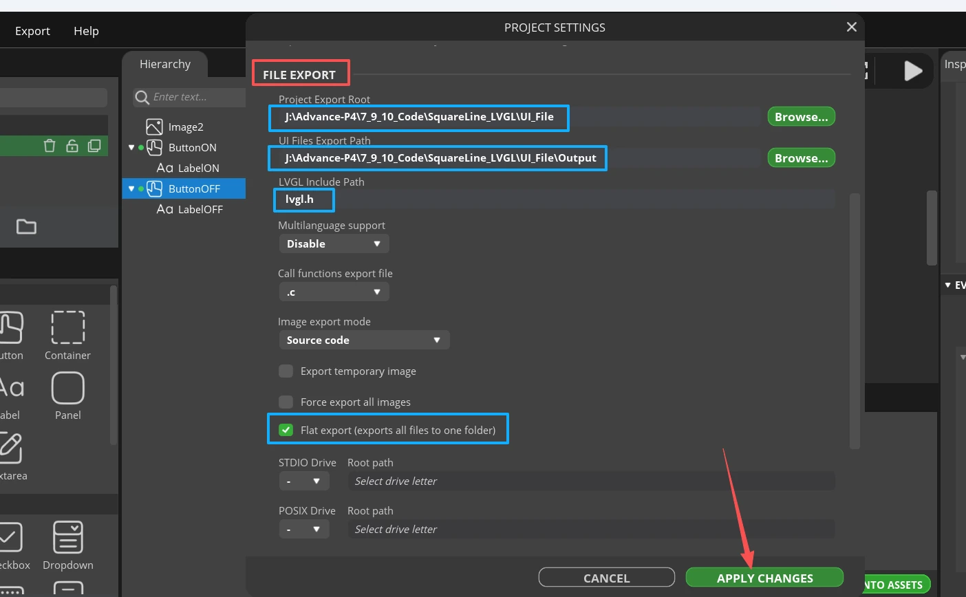
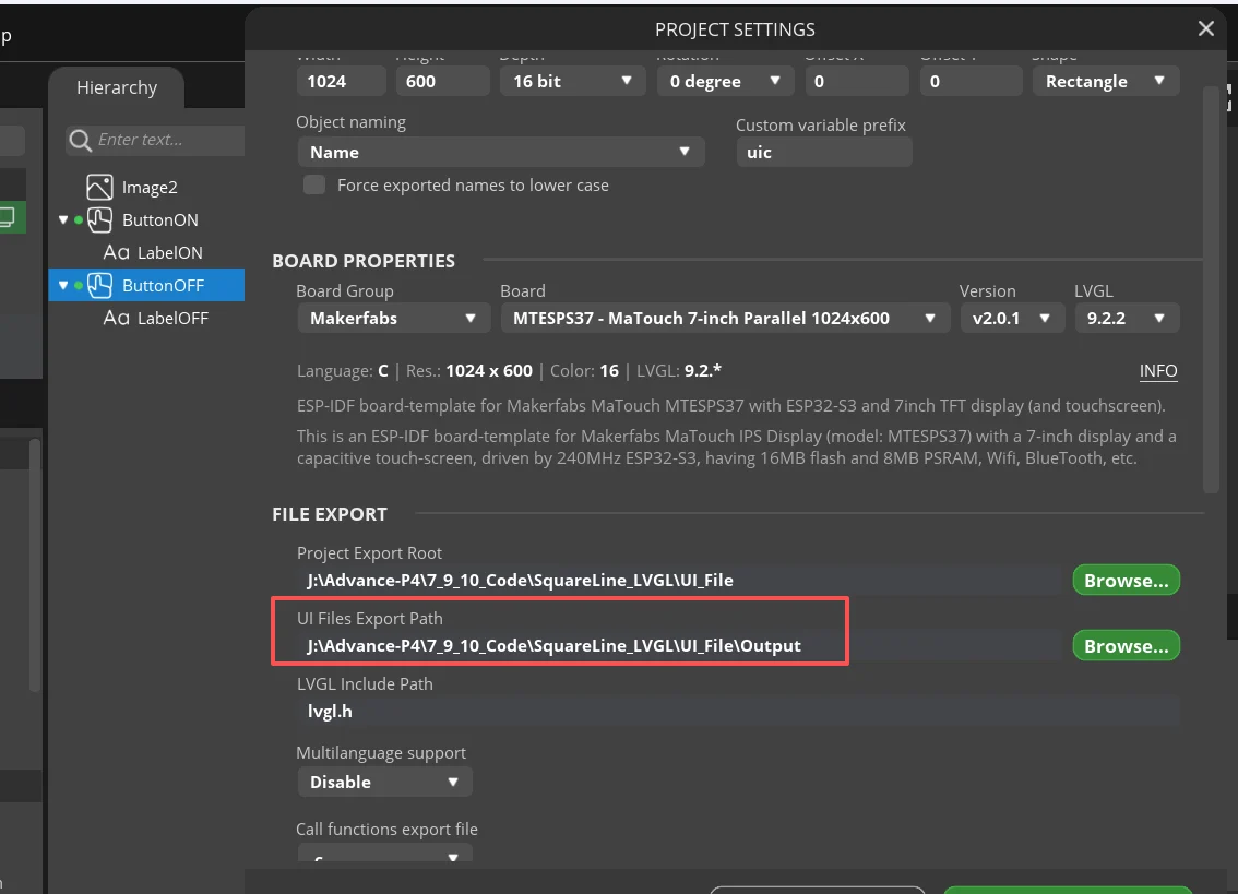
Click File and select Project Settings.
Specify the export path where the exported UI files will be saved.
Then click Export UI Files, and the UI interface you designed will be exported.
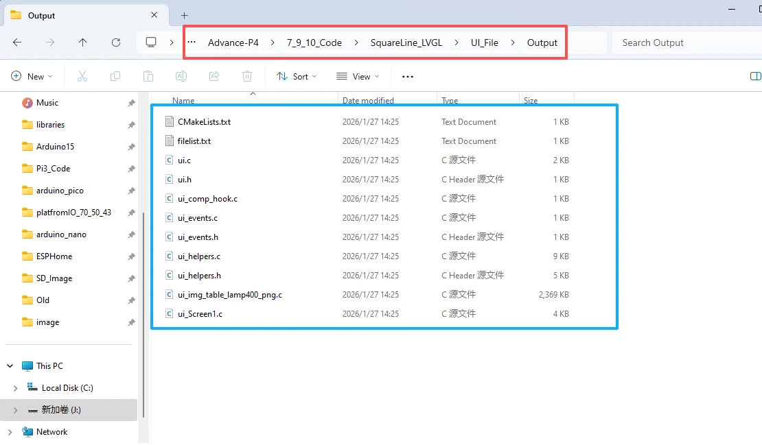
Then navigate to the specified export path to view the exported UI files.
4.4 Integrate the UI Files into the Project
Prerequisite: This project is modified based on the ESP-IDF Lesson 9 code.
Under the main folder, create a folder named ui.
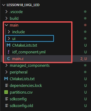
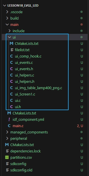
Place the exported UI files into the ui folder.
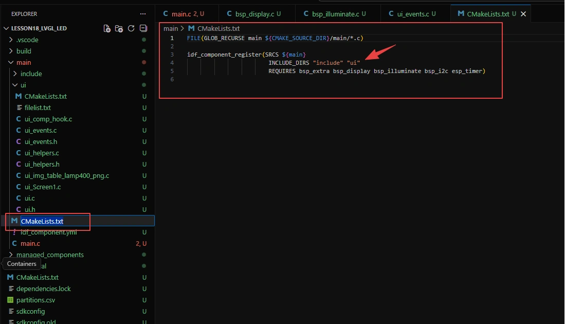
In the CMakeLists.txt file under the main folder, add ui so that main.c can locate the ui files.
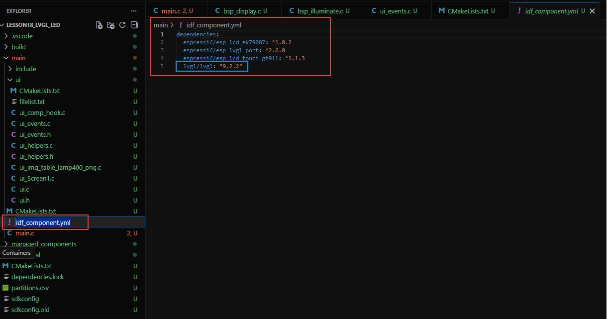
Then specify LVGL version 9.2.2 in idf_component.yml under the main folder.
Finally, add #include "ui.h" in main.c so that it can locate your designed UI files step by step through ui.h.
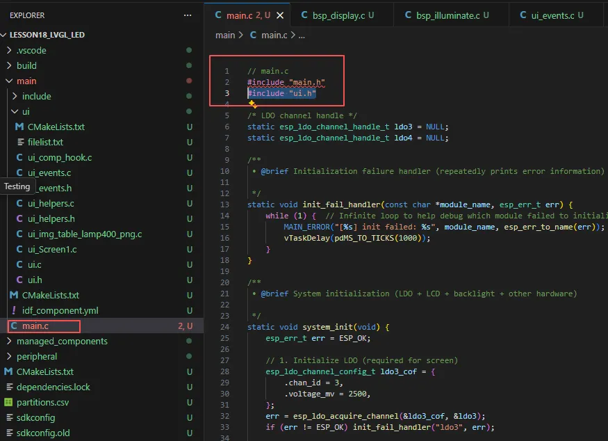
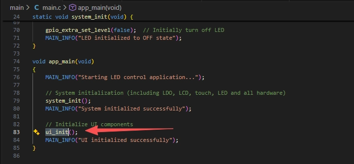
Also add ui_init() in main.c so that the UI interface can be displayed.
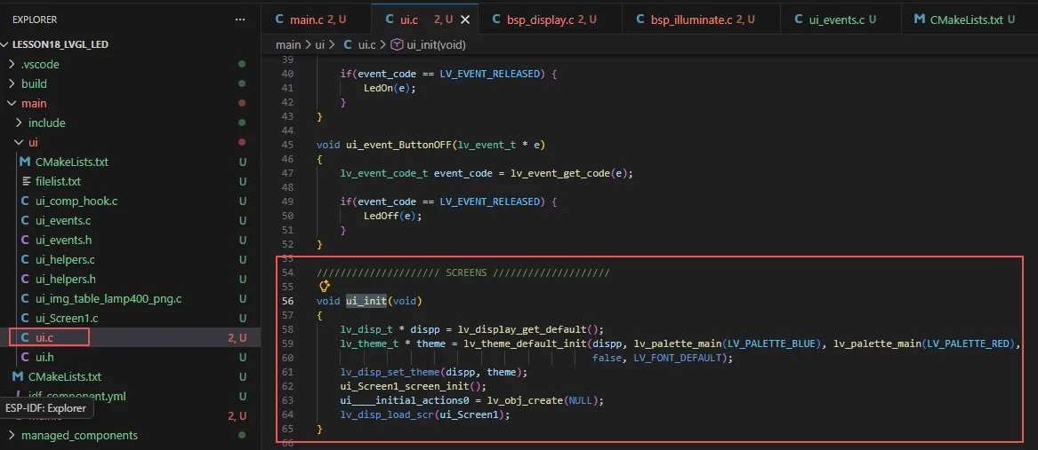
Because in ui.c, ui_init() includes all the UI elements.
4.5 Add Callback Functionality
Previously, we added events to both buttons in SquareLine Studio. In order to turn the LED on and off by clicking the buttons, we had only defined two callback functions without implementing them. Now, we will implement this functionality.
Go to the ui folder under the main directory and locate the ui_events.c file.
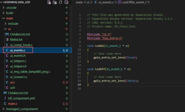
Add these three lines of code here.
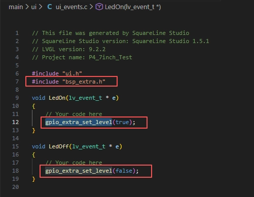
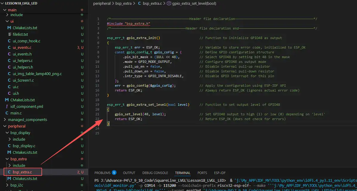
#include "bsp_extra.h": This library is added because the gpio_extra_set_level function used in this file comes from the bsp_extra component, which is required to control the LED connected to pin 48.
That is:
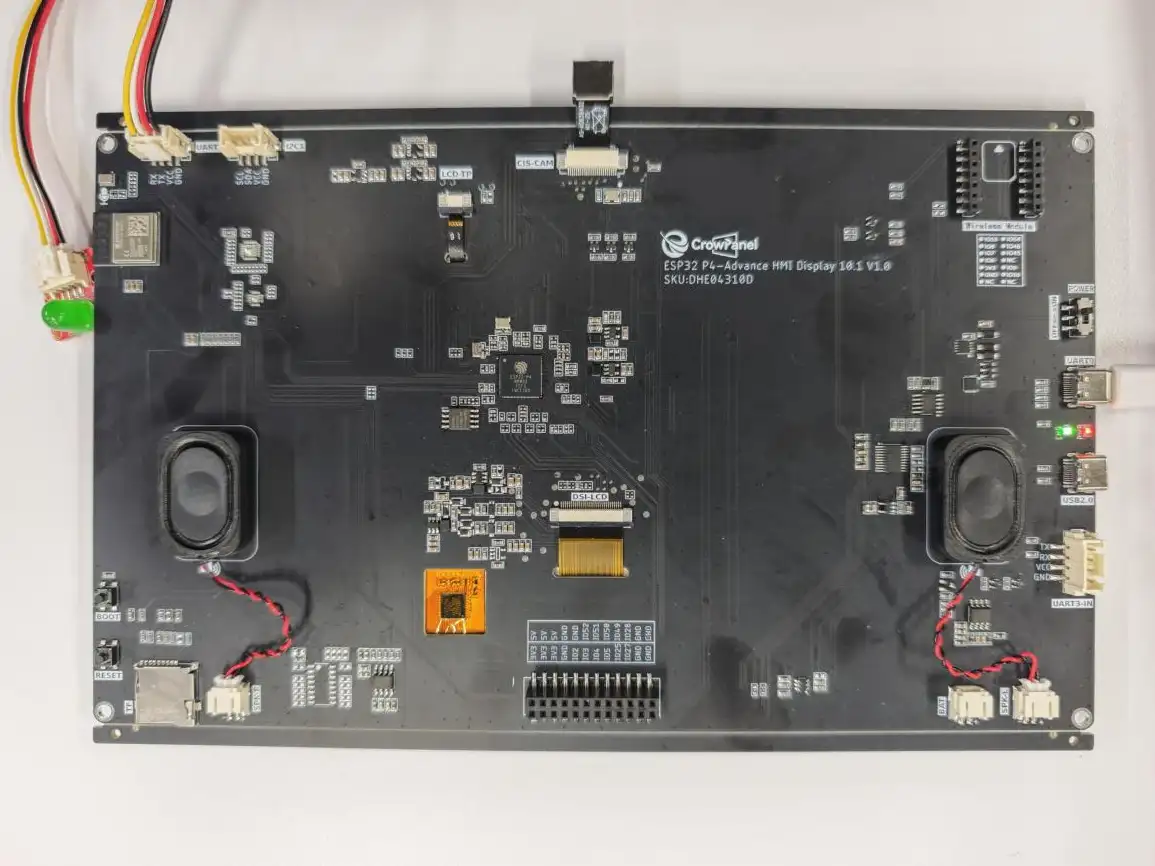
remember to connect an LED to the UART1 interface.
At this point, both our UI interface and code design are complete.
5. Complete Code
Kindly click the link below to view the full code implementation.
6. Programming Steps
Now the code is ready. Next, we need to flash the ESP32-P4 so that we can observe the results.
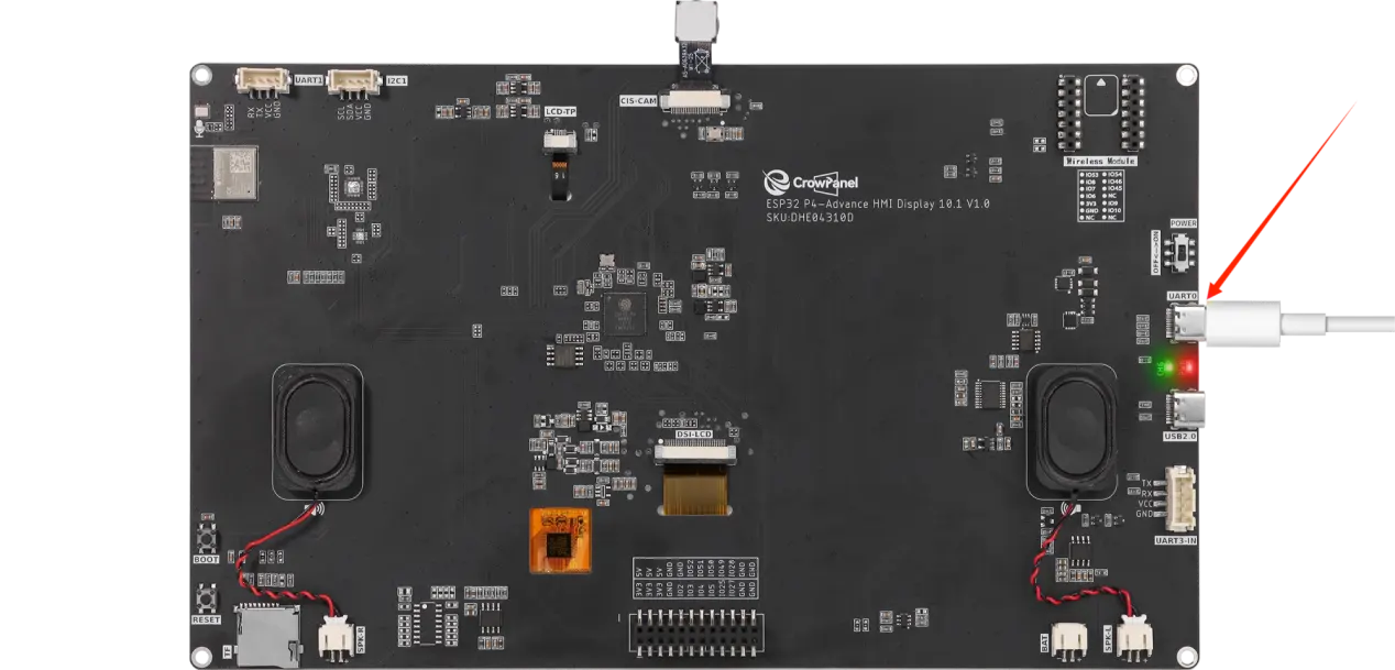
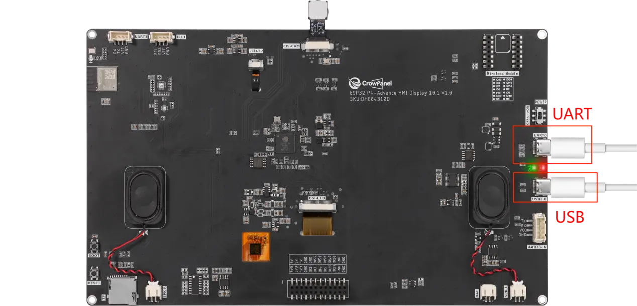
First, we connect the Advance-P4 device to our computer host via the USB cable.
Configure the project.
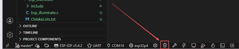
Before starting the burning process, delete all the compiled files and restore the project to its initial "uncompiled" state. (This ensures that the subsequent compilation will not be affected by your previous actions.)
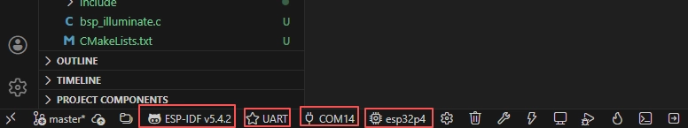
Following the steps in the first section, first select the ESP-IDF version, the code upload method, the serial port, and the chip to be used.
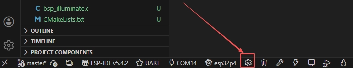
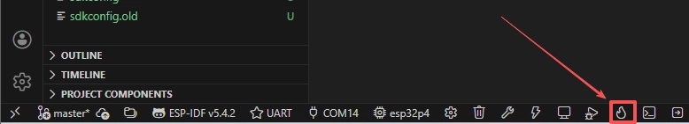
Then we need to configure the SDK.
Click the icon in the picture below.
Wait for a moment for the loading process to complete, and then proceed with the related SDK configuration.
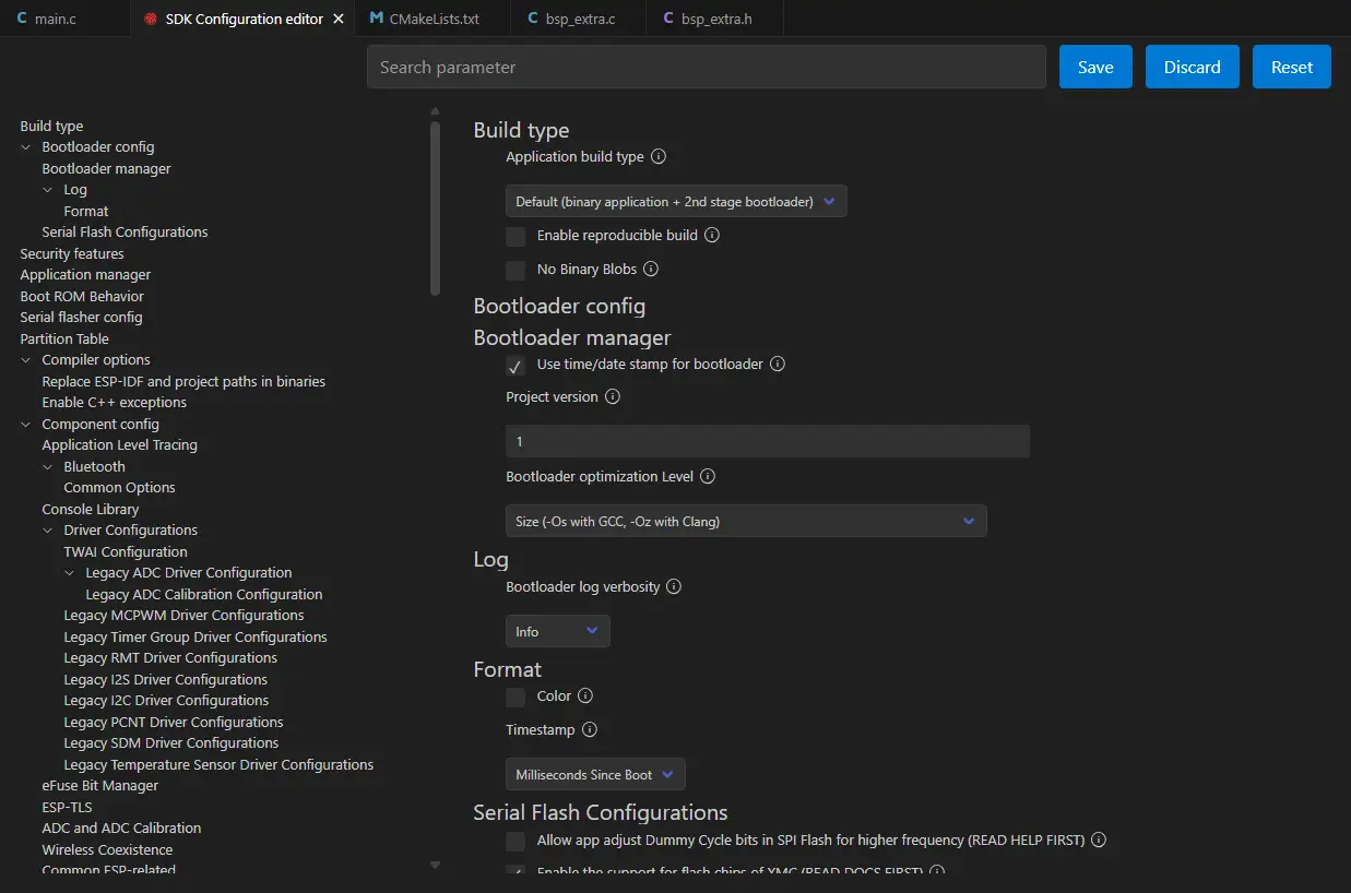
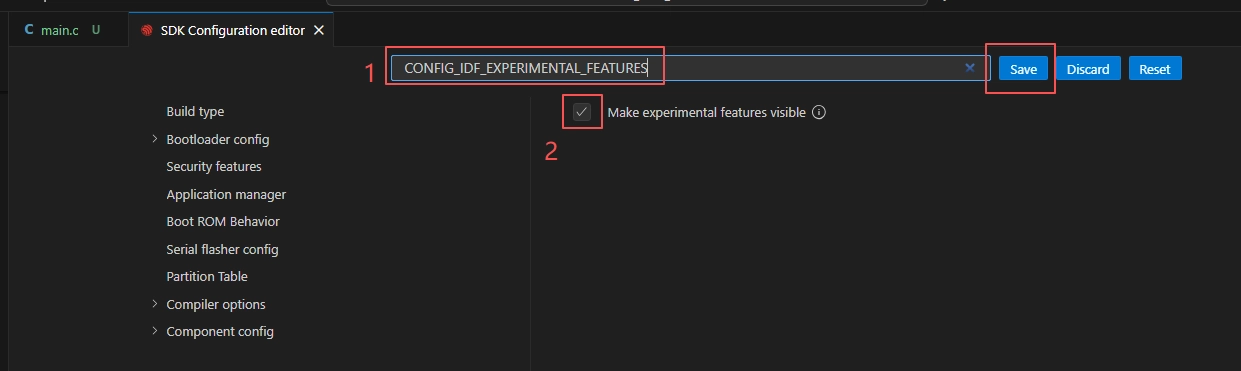
After the SDK configuration is enabled, search for "CONFIG_IDF_EXPERIMENTAL_FEATURES" in the search box, check the box, and then save the configuration.
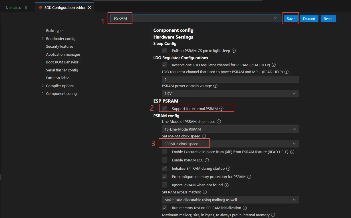
Enable the PSRAM option to allocate sufficient RAM to the screen.
Enable the above CONFIG_IDF_EXPERIMENTAL_FEATURES option to select 200M PSRAM and use a higher RAM speed.
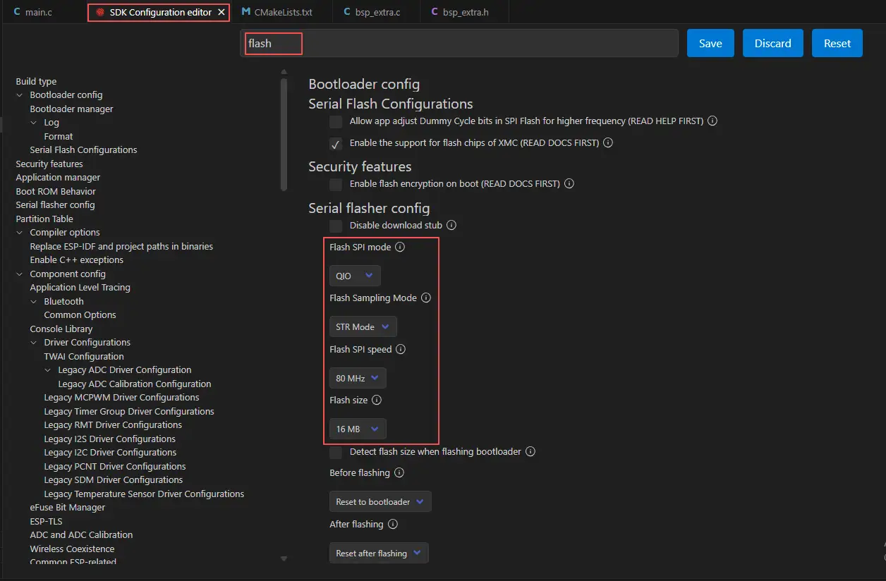
Then search for "flash" in the search box.
(Make sure your flash settings are the same as mine.)
Then select the partition table option we provide. Since the UI files contain image files, a larger partition table is required. We have prepared one for you; just use our partition table.
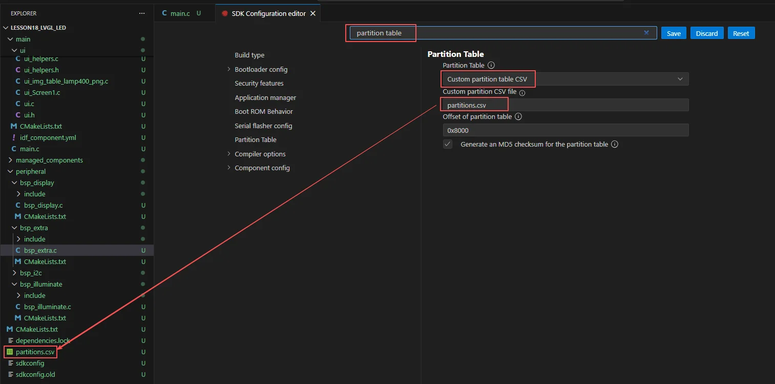
After the configuration is completed, remember to save your settings.
Finally, since the label font we designed uses LVGL font size 48,
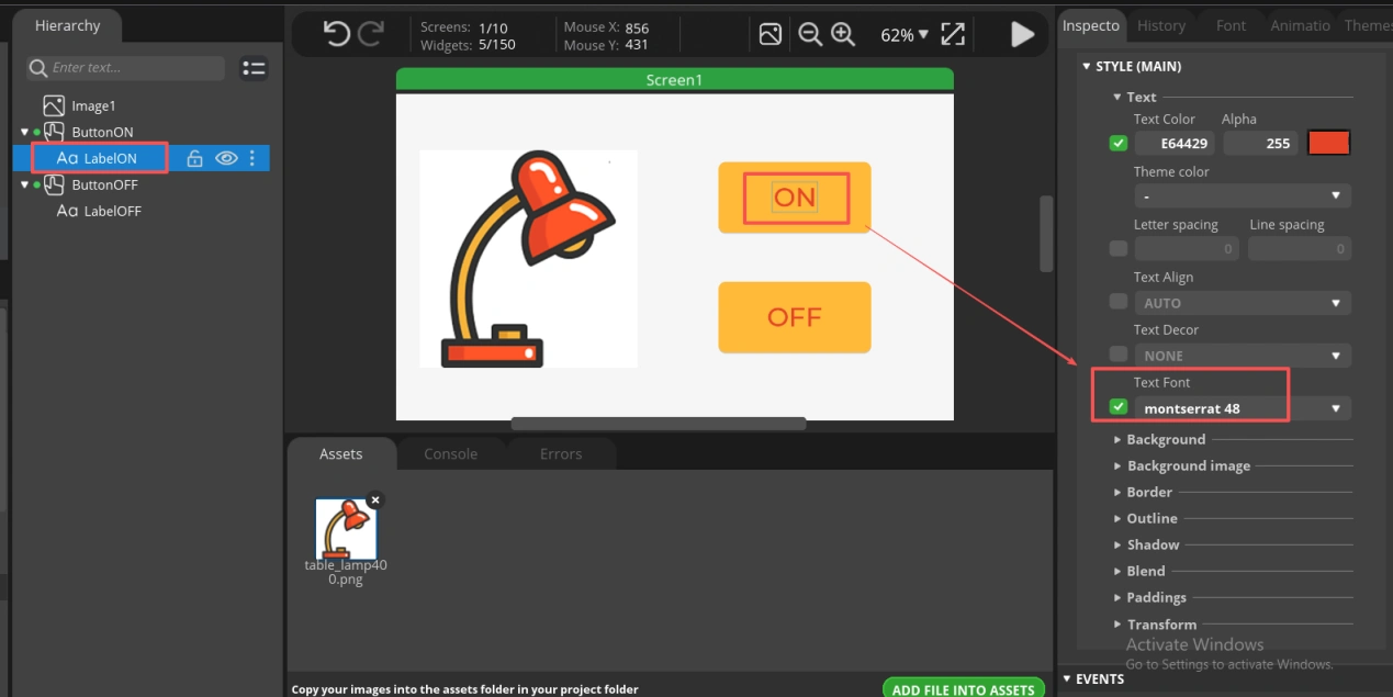
We need to enable it before it can be used in the project.
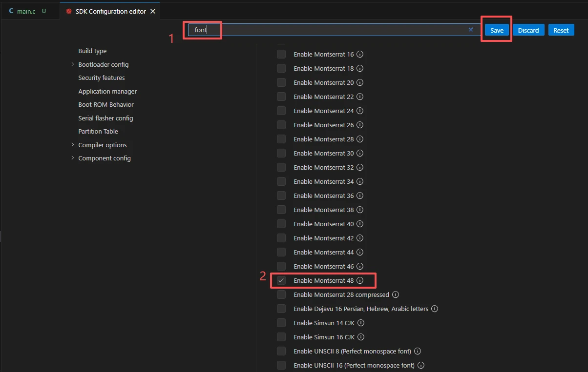
After the configuration is completed, remember to save your settings.
Then we will compile and flash the code (as detailed in the first lesson).
Here, we would like to introduce a very convenient feature. With just one button press, you can perform compilation, upload, and open the monitor at once. (This is provided that the entire code is error-free.)
After a moment of waiting, the code compilation and upload were completed, and the display also turned on.
Suggestion: Please remember to connect your Advance-P4 using another Type-C data cable via the USB2.0 interface. This interface provides a maximum current of approximately 500 milliamps from the USB-A port of the computer. When the Advance-P4 uses more external devices, especially the screen, it requires a sufficient current source.
After the upload is successful, you will see this beautifully designed interface.

When you click the ON button on the screen, you will be able to turn on the LED.
When you click the OFF button on the screen, you will be able to turn off the LED.