PlatformIO_LVGL_4.3: Driving a 4.3-inch HMI, XPT2046 Touch, and LVGL 9.1 with PlatformIO
1. Course Introduction
In this lesson, we use Visual Studio Code, PlatformIO, the Arduino framework, LVGL 9.1.0, and Arduino GFX 1.6.5 to drive a 4.3-inch, 480 × 272 HMI display based on the ESP32-S3. The LCD is connected via a 16-bit RGB parallel bus, and the touch controller is an XPT2046 read through a separate SPI bus.
Learners will open the course project PlatformIO43 and complete dependency installation, compilation, serial port selection, and firmware flashing. After the program runs, the LCD displays the background and the ON and OFF image buttons exported from SquareLine Studio 1.6.1. When the screen is touched, the serial port outputs the mapped coordinates. After tapping the ON button, the GPIO 38 LED lights up; after tapping the OFF button, the LED turns off.
Reference materials:
2. Learning Objectives
- Be able to install the PlatformIO IDE in VS Code and open a complete project that contains
platformio.ini. - Be able to explain the roles of
platformio.ini, the custom board JSON,src/, andinclude/in this project. - Be able to describe the control signals, data lines, synchronization timing, and pixel clock parameters of the 480 × 272 RGB LCD.
- Be able to describe the data flow among the XPT2046 raw coordinates, calibration mapping, and the LVGL pointer input.
- Be able to complete project compilation, serial port selection, flashing, and serial monitoring, and determine whether the experiment succeeded based on the UI, touch coordinates, and the GPIO 38 LED.
- Be able to place the LVGL 9.1.0 UI files exported from SquareLine Studio into the correct PlatformIO directory.
3. Preparations
3.1 Hardware
- One CrowPanel ESP32-S3 4.3-inch HMI development board, with a resolution of 480 × 272 and an XPT2046 touch controller.
- One LED module, connected to the board's GPIO_D interface, which corresponds to GPIO 38.
- One USB data cable that supports data transfer.
3.2 Software and Project
- Visual Studio Code.
- PlatformIO IDE extension.
- The complete course project
PlatformIO43. - The PlatformIO platform package
platform-espressif32 55.03.38release package fixed for use by this project. - LVGL
9.1.0. - Arduino GFX Library
1.6.5. - XPT2046_Touchscreen, with the version pinned by the commit hash in
platformio.ini. - SquareLine Studio
1.6.1, needed only when recreating the UI.
The first build needs to download the platform package, toolchain, and dependent libraries, so a network connection should be maintained.
The project uses core_dir and packages_dir to keep the PlatformIO core and tool packages inside the project's .pio directory.
.pio is a generated cache and is not part of the source code that needs to be published: do not manually modify the libraries and tools inside it, and do not copy a .pio from another computer or an old path into this one. If, after moving the project, the virtual environment still points to the old Python path, close VS Code, remove the project's .pio, then reconnect to the network, open the project, and let PlatformIO regenerate it.
4. Software Operation Steps
Open VS Code, search for and install PlatformIO IDE in the Extensions panel on the left. After installation, restart VS Code as prompted; the PlatformIO icon should appear in the left activity bar.

After installation, restart VS Code; the PlatformIO icon should appear on the left. Click the icon to enter the PIO Home main page.

In the PIO Home Quick Access area, click Open Project.

Select the course directory PlatformIO43, confirm that the directory directly contains platformio.ini, then click Open "PlatformIO43". Do not open only src/main.cpp, otherwise PlatformIO will not be able to read the board and dependency configuration.

Verify the project structure in the Explorer:
-
platformio.ini: platform, board, memory mode, compile macros, and dependency versions. -
esp32-s3-devkitc-1-myboard.json: ESP32-S3 custom board, Flash, PSRAM, partition, and upload parameters. -
huge_app.csv: application partition table. -
src/main.cpp: main program for RGB LCD, touch, LVGL, and GPIO. -
src/ui*.c: UI implementation and image arrays exported from SquareLine Studio. -
include/touch.h,include/ui*.h: touch configuration and UI header files.

Connect the CrowPanel board to a USB port on the computer using a USB data cable.

Select the device serial port: look at the VS Code bottom status bar; the dropdown on the left defaults to Auto. Click the dropdown and select the serial port corresponding to the board (example: COM13).

Click the right-arrow icon (PlatformIO: Upload) in the VS Code bottom status bar. Wait for the compilation and upload process to run automatically.
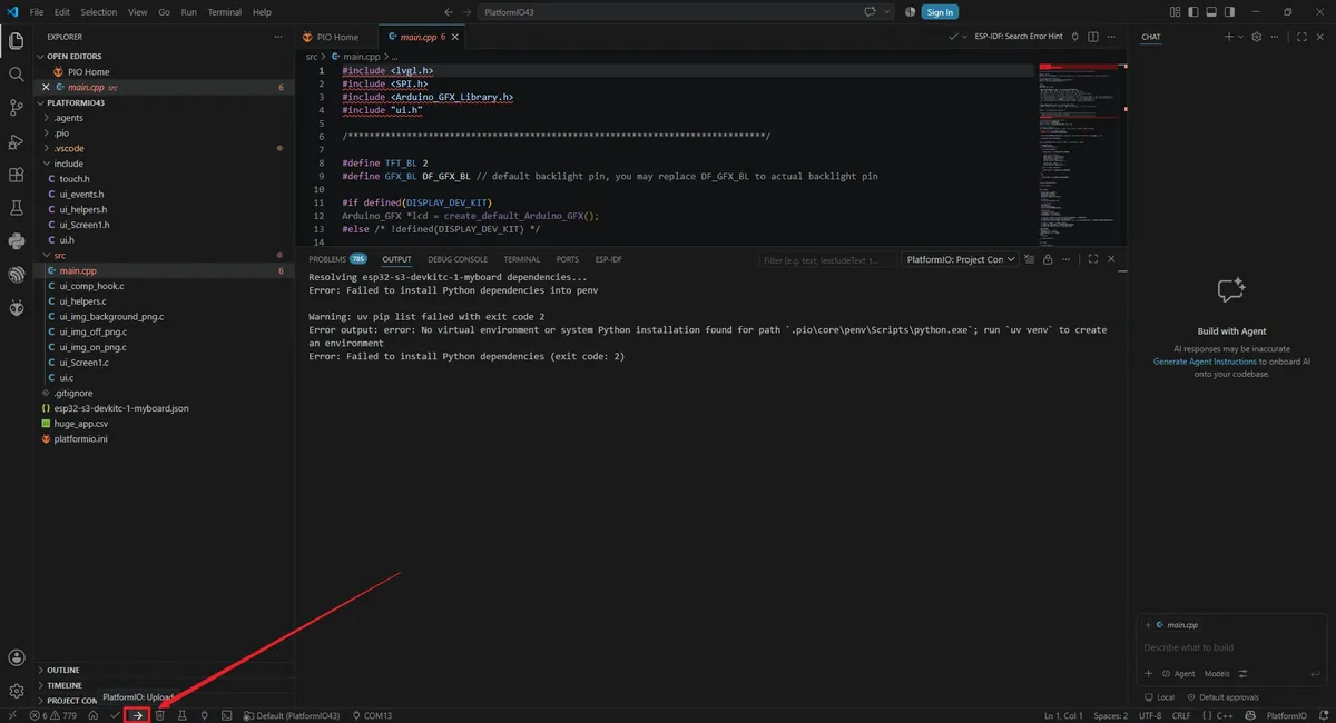


5. Hardware Operation Steps
Keep the board powered off and confirm that the LCD and touch flex cables are secured. If using an external LED, connect it to the interface labeled GPIO_D, with the signal line corresponding to GPIO 38; after confirming the orientation and power pins, connect to the computer using a USB-C cable that supports data transfer.

After flashing is complete, press the reset button. The LCD backlight should turn on, and the screen should fully display the background and the two image buttons ON and OFF; there must be no corrupted display, misalignment, white blocks, or missing sections.

Tap the ON image button with a finger; do not use sharp or conductive objects. The GPIO 38 LED should light up.

Tap the OFF image button; the GPIO 38 LED should turn off.

6. Key Code Explanation
6.1 PlatformIO Platform, Board, and Dependency Configuration
; Keep PlatformIO project metadata and downloaded packages inside this project.
; This makes the course project easier to move as a complete folder.
[platformio]
boards_dir = .
core_dir = .pio/core
packages_dir = .pio/packages

[env:esp32-s3-devkitc-1-myboard]
; Use the verified ESP32 Arduino platform package for this lesson.
platform = https://github.com/pioarduino/platform-espressif32/releases/download/55.03.38/platform-espressif32.zip
board = esp32-s3-devkitc-1-myboard
framework = arduino

; The 4.3-inch board uses QIO flash and PSRAM.
board_build.arduino.memory_type = qio_qspi
build_flags = -DBOARD_HAS_PSRAM
    -DLV_CONF_SKIP

; Lock library versions so the lesson result does not change unexpectedly.
lib_deps =
    lvgl/lvgl@9.1.0
    paulstoffregen/XPT2046_Touchscreen@0.0.0-alpha+sha.26b691b2c8
    moononournation/GFX Library for Arduino@1.6.5
This configuration is read by PlatformIO before the build, and its purpose is to fix "which board, which framework, and which library versions this lesson uses." boards_dir = . tells PlatformIO to read the custom board JSON from the project root; core_dir and packages_dir place the generated cache inside the current project's .pio directory; lib_deps pins the versions of LVGL, XPT2046, and Arduino GFX to keep the build behavior as consistent as possible across different computers.
The custom board file also specifies the ESP32-S3, 240 MHz CPU, 80 MHz QIO Flash, 4 MB Flash, Huge APP partition, and 921600 upload speed. Without the JSON, an unknown board error will be reported; after changing the platform or library version, Arduino Core API incompatibilities may appear; with an incorrect memory mode, the board may reset during startup or fail to use PSRAM. When troubleshooting, first restore the original course platformio.ini and board JSON; do not directly modify the packages downloaded into .pio.
6.2 RGB LCD Pins and Timing
/*---------------------------------------------------------------
 * Configure the RGB display bus
 * Match the ESP32-S3 pins and LCD timing used by the 4.3-inch panel.
 *--------------------------------------------------------------*/
Arduino_ESP32RGBPanel *bus = new Arduino_ESP32RGBPanel(
  40, 41, 39, 42,
  45, 48, 47, 21, 14,
  5, 6, 7, 15, 16, 4,
  8, 3, 46, 9, 1,
  0, 8, 4, 43,
  0, 8, 4, 12,
  1, 9000000, false,
  0, 0, 480
);

Arduino_RGB_Display *lcd = new Arduino_RGB_Display(
  480, 272, bus, 0, false
);
This set of objects is created globally before the program starts; the hardware is truly initialized only after setup() calls lcd->begin(). The first four parameters of Arduino_ESP32RGBPanel connect DE, VSYNC, HSYNC, and PCLK in order, and the next three groups connect the RGB565 red, green, and blue data lines. The horizontal and vertical timing determines how each row and each frame is synchronized; 9000000 indicates a 9 MHz pixel clock; Arduino_RGB_Display(480, 272, ...) tells Arduino GFX and LVGL that the screen's actual display area is 480 × 272.
Incorrect data pins usually show up as abnormal colors or no display; incorrect synchronization parameters may cause scrolling, shifting, or a black screen; incorrect width/height will make the LVGL refresh area inconsistent with the physical screen. These parameters are bound to the PCB routing and the LCD panel and cannot be copied from the configuration of a 2.4-inch SPI screen.
6.3 LVGL Partial Buffer and Screen Refresh Callback
// Stores one partial LVGL render buffer. A smaller buffer saves RAM,
// while LVGL refreshes the screen in several rectangular pieces.
static lv_color_t disp_draw_buf[480 * 272 / 8];

/**
 * @brief Copy one rendered LVGL area to the RGB LCD.
 *
 * LVGL calls this function whenever a part of the UI needs to be
 * redrawn. The callback sends the RGB565 pixel data to Arduino GFX
 * and then notifies LVGL that the buffer can be reused.
 *
 * @param disp LVGL display object that requested the refresh.
 * @param area Rectangle area that needs to be updated.
 * @param px_map Pixel buffer generated by LVGL.
 * @return None.
 * @note Called automatically by LVGL after it is registered in setup().
 */
void my_disp_flush(lv_display_t *disp,
                   const lv_area_t *area,
                   uint8_t *px_map)
{
  // Convert the LVGL area into width and height values required by Arduino GFX.
  uint32_t w = lv_area_get_width(area);
  uint32_t h = lv_area_get_height(area);

  lcd->draw16bitRGBBitmap(area->x1, area->y1,
                          reinterpret_cast<uint16_t *>(px_map),
                          w, h);
  lv_display_flush_ready(disp);
}
The drawing buffer holds one eighth of the full-screen pixel count, so LVGL does not occupy the entire screen's RAM at once but refreshes in blocks. my_disp_flush() is the most critical bridge function in the display chain: LVGL is responsible for generating the pixels, and Arduino GFX is responsible for sending those pixels to the RGB LCD. After the transfer completes, you must call lv_display_flush_ready(); otherwise LVGL will keep waiting for the previous area to finish, and the picture usually freezes at the first refresh.
Increasing the buffer reduces the number of blocks but increases RAM usage; reducing the buffer increases the number of callbacks and copies. Before changing it, confirm the system's available memory; do not directly change it to a full-screen double buffer.
6.4 XPT2046 Pins and Coordinate Mapping
/*---------------------------------------------------------------
 * Select and configure the touch controller
 * Use XPT2046 on a separate SPI bus for this 4.3-inch board.
 *--------------------------------------------------------------*/
#define TOUCH_XPT2046
#define TOUCH_XPT2046_SCK 12
#define TOUCH_XPT2046_MISO 13
#define TOUCH_XPT2046_MOSI 11
#define TOUCH_XPT2046_CS 0
#define TOUCH_XPT2046_INT 36
#define TOUCH_XPT2046_ROTATION 0
#define TOUCH_MAP_X1 4000
#define TOUCH_MAP_X2 100
#define TOUCH_MAP_Y1 100
#define TOUCH_MAP_Y2 4000

// Store the latest mapped touch point for the LVGL input callback.
int touch_last_x = 0, touch_last_y = 0;
touch_init() uses GPIO 12, 13, 11, and 0 to initialize the touch SPI, with the bus interrupt pin at GPIO 36. The XPT2046 returns raw ADC values close to 0–4095, which the project then converts to screen coordinates using map().
The current course code maps the X axis to 0–429 and the Y axis to 0–271:
/**
 * @brief Read the XPT2046 point and convert it to screen coordinates.
 *
 * The controller reports raw ADC values. The map ranges translate
 * those values into the coordinate system used by LVGL.
 *
 * @param None.
 * @return true if a valid touch point was read.
 * @return false if the screen is not being touched.
 * @note Called by my_touchpad_read() whenever LVGL asks for input data.
 */
bool touch_touched()
{
  if (ts.touched()) {
    TS_Point p = ts.getPoint();

    // Keep the calibration ranges exactly aligned with the verified lesson code.
    touch_last_x = map(p.x, TOUCH_MAP_X1, TOUCH_MAP_X2, 0, 430 - 1);
    touch_last_y = map(p.y, TOUCH_MAP_Y1, TOUCH_MAP_Y2, 0, 272 - 1);
    return true;
  }

  return false;
}
The X-axis range is smaller than the LCD's 480-pixel width; this is the existing project's calibration parameter, and the tutorial records it faithfully according to the source code. If the right-side area is hard to tap, first log the four-corner raw values on the serial port, then adjust the endpoints and target range based on actual measurements; do not simply change 430 to 480 and consider the calibration done. The endpoint order determines the coordinate direction; writing it in reverse causes mirroring.
6.5 Registering LVGL Display and Touch Input
/*---------------------------------------------------------------
 * Register LVGL display and input drivers
 * Connect LVGL to the LCD flush callback and the touch read callback.
 *--------------------------------------------------------------*/
screenWidth = lcd->width();
screenHeight = lcd->height();

// Create an LVGL display that has the same size as the physical LCD.
lv_display_t *disp = lv_display_create(screenWidth, screenHeight);
lv_display_set_flush_cb(disp, my_disp_flush);
lv_display_set_buffers(disp, disp_draw_buf, NULL,
                       sizeof(disp_draw_buf),
                       LV_DISPLAY_RENDER_MODE_PARTIAL);

// Register the touch panel as a pointer device so LVGL buttons can receive clicks.
lv_indev_t *indev = lv_indev_create();
lv_indev_set_type(indev, LV_INDEV_TYPE_POINTER);
lv_indev_set_read_cb(indev, my_touchpad_read);

// Build the screen, background image, buttons, and button events exported from SquareLine Studio.
ui_init();
This code runs once inside setup(). The display object is bound to a local buffer and the flush callback, the input object registers my_touchpad_read() as the pointer device read function, and finally ui_init() creates the interface exported from SquareLine Studio.
If the flush callback is not registered, LVGL cannot send the framebuffer to the LCD; if the input callback is not registered, the interface can be displayed but the buttons will not respond; if ui_init() is not called, the backlight and driver may work normally, but the background and buttons for this lesson will not be created.
6.6 Passing the Touch State to LVGL
/**
 * @brief Provide the latest touch state to LVGL.
 *
 * LVGL does not read the XPT2046 controller directly. Instead, it
 * calls this function to ask whether the pointer is pressed and where
 * the latest touch point is located.
 *
 * @param indev LVGL input device object.
 * @param data Output structure that receives press state and coordinates.
 * @return None.
 * @note Called repeatedly by lv_timer_handler().
 */
void my_touchpad_read(lv_indev_t *indev, lv_indev_data_t *data)
{
  LV_UNUSED(indev);
  if (touch_has_signal()) {
    if (touch_touched()) {
      // A valid touch point should be sent as PRESSED with the last mapped position.
      data->state = LV_INDEV_STATE_PRESSED;
      data->point.x = touch_last_x;
      data->point.y = touch_last_y;

      // Serial output helps verify whether the touch driver and calibration are working.
      Serial.print("Data x :");
      Serial.println(touch_last_x);
      Serial.print("Data y :");
      Serial.println(touch_last_y);
    } else if (touch_released()) {
      data->state = LV_INDEV_STATE_RELEASED;
    }
  } else {
    data->state = LV_INDEV_STATE_RELEASED;
  }
}
LVGL calls this function repeatedly while running its timer tasks. When a valid touch is detected, the function reports PRESSED along with the coordinates; when there is no signal or the touch is released, it reports RELEASED. If you keep reporting the pressed state, widgets behave as if they are held down continuously; if you keep reporting the released state, the buttons will not respond. The serial coordinates are the direct basis for distinguishing between "the touch hardware is not reading any data" and "the UI click area does not match."
6.7 UI Events Control GPIO 38
/**
 * @brief Handle clicks on the ON button.
 *
 * The UI event does not drive the GPIO directly. It only records the
 * desired LED state, and the main loop applies that state to GPIO 38.
 *
 * @param e LVGL event object for Button1.
 * @return None.
 * @note Called by LVGL when Button1 receives LV_EVENT_CLICKED.
 */
void ui_event_Button1(lv_event_t *e)
{
    if(lv_event_get_code(e) == LV_EVENT_CLICKED) {
        led = 1;
    }
}

/**
 * @brief Handle clicks on the OFF button.
 *
 * This callback clears the shared LED state. The main loop then writes
 * the low level to GPIO 38.
 *
 * @param e LVGL event object for Button2.
 * @return None.
 * @note Called by LVGL when Button2 receives LV_EVENT_CLICKED.
 */
void ui_event_Button2(lv_event_t *e)
{
    if(lv_event_get_code(e) == LV_EVENT_CLICKED) {
        led = 0;
    }
}
/*---------------------------------------------------------------
 * Initialize the LED output.
 * Run this part once in setup() before LVGL starts handling events.
 *--------------------------------------------------------------*/
pinMode(38, OUTPUT);
digitalWrite(38, LOW);

/**
 * @brief Keep LVGL running and apply the latest LED state.
 *
 * The timer handler refreshes the UI and reads touch input. The LED is
 * updated after each LVGL cycle so button clicks quickly affect GPIO 38.
 *
 * @param None.
 * @return None.
 * @note Called continuously by the Arduino runtime.
 */
void loop()
{
lv_timer_handler();
if(led == 1) digitalWrite(38, HIGH);
if(led == 0) digitalWrite(38, LOW);
delay(50);
}
The event functions for both buttons only modify the shared variable led, and the main loop then outputs that state to GPIO 38. This keeps the LVGL callbacks short. When the buttons show visual feedback but the LED does not actuate, you should check whether the event is LV_EVENT_CLICKED, whether extern int led exists, and whether the main loop is continuously performing the GPIO write.
lv_timer_handler() must be called periodically; otherwise both display refresh and input handling will stop. The current loop delay is 50 ms; increasing the delay significantly will slow down touch and UI responsiveness, and adding long blocking tasks inside the loop produces the same effect.
7. UI Asset Creation and Integration
This section uses SquareLine Studio 1.6.1 to demonstrate the UI creation workflow again. The course already provides the exported UI files, so beginners can first read this section to understand the process, then compile directly using the files in the project. When creating a new project, you must select LVGL 9.1.0;
How to download SquareLine Studio:https://www.elecrow.com/wiki/Create_LVGL_UI_with_SquareLine_Studio.html.
Launch SquareLine Studio 1.6.1, click Create, and select the Arduino with TFT_eSPI template for the Arduino platform. This template generates the UI file framework suitable for Arduino and TFT_eSPI projects.
Note:When the Arduino framework is selected, SquareLine Studio only displays the Arduino with TFT_eSPI option. It generates template code suited for TFT_eSPI, but SquareLine Studio also supports other graphics libraries; when switching to other hardware, you need to modify the display code according to the actual library.

Enter the project name SquareLine_Project, set the resolution to width 480 and height 272, set the color depth to 16 bit, set the LVGL version to 9.1.0, then click CREATE.

Explanation:A 16 bit color depth can represent 65,536 colors using the RGB 5:6:5 pixel format. Keep it consistent with the project's color configuration.
After the project opens, select Screen1 in Screens on the left.

In the Assets area, click ADD FILE TO ASSETS and import the background.png, on.png, and off.png provided with the course. After importing, three thumbnails should appear.
Material link:

Select Screen1, expand STYLE SETTINGS > STYLE (MAIN) > Background on the right, and enable the background image setting. 
In Bg Image, select background, and disable unneeded page scrolling. The background should fully cover the 480 × 272 canvas. 
In Widgets on the left, click Button to add Button1 to Screen1, then move the button to the ON area on the left side of the screen. 
Select Button1 and set its position and size in Transform. 
Expand Button1's STYLE (MAIN) > Background and select on.png. The ON icon should appear on the canvas, and the image should not be stretched or cropped. 
Duplicate Button1 to create Button2 and move it to the OFF area on the right side. Duplicating preserves the same size and base style. 
In Button2's background setting, select off.png, and confirm that the ON and OFF images are on the left and right sides of the screen respectively. 
Select the button, check the DEFAULT state in STATE, and set the displayed background color to white. 
Switch to the PRESSED state, set a recognizable press feedback, and set the displayed background color to red. 
Set the same parameters for the "OFF" button.

Note: Because the buttons can control the LED on/off state, we can add any event here to handle button events. These events will be used as a code framework when the UI files are exported. Later, we will modify the button event code to control the LED on/off state.
Select Button1, open the EVENTS panel and click ADD EVENT to create the first button event. 
Select "CLICKED" as the trigger condition, and choose the trigger event in "Action". This will be modified later in the generated program to implement the LED control function.

Note:Since the buttons ultimately control the LED on/off, you can add any event here first to let the exported UI file generate the button event code framework; the LED control code will be modified in a later step.
Complete this event. Here, I choose to switch screens, that is, switch to the Screen1 screen.

Add an event for Button2 using the same method. The two buttons must generate different event functions, into which the ON and OFF states will be written separately later. 
Click Run.

Open File > Project Settings, then configure the relevant settings for the exported files.


Set the export directory to an easy-to-find pure-English path, create a new output folder, fill in and confirm that the LVGL Include Path is lvgl.h, then click APPLY CHANGES after confirming.


Tip:After selecting Flat export, all output files are placed in the same folder, so the program does not need to modify file paths. If Flat export is not selected, files are scattered across different folders and the compiler may not recognize them automatically, usually requiring manual path modifications, so it is recommended to keep it checked.
Click Export > Export UI Files. Wait for the export to complete. After completion, ui.c, ui.h, ui_Screen1.c, event files, helper files, and image array files should appear in the target directory.


Add the UI files to the PlatformIO project. We need to add the UI files from SquareLine Studio to the PlatformIO project. The .c files of the user interface should be placed in the project's /src folder, and the .h files should be placed in the /include folder.


8. Observed Behavior
After the program resets, the serial port first outputs startup information, then the LCD backlight turns on and display initialization completes. Once running stably, the screen shows the full background and two image buttons. While a finger is pressed on the screen, the serial port continuously outputs the mapped x and y coordinates; after clicking the ON button on the left, the GPIO 38 indicator lights up, and after clicking the OFF button on the right, the indicator turns off.
ON -> LED lights up.

OFF -> LED turns off.

9. Code Download
- PlatformIO project: PlatformIO43.