5.Port Introduction
Welcome to Lesson 5 of the CrowPanel ESP32 Advance HMI Series Tutorial, Port Introduction.
This lesson will use the IIC interface and UART1-OUT interface of this series of products to collect data from temperature and humidity sensors. When the temperature exceeds the threshold, the light bulb will automatically light up.
In this lesson, we will use the knowledge of LVGL graphics library from Lesson 3 to create an interactive interface.
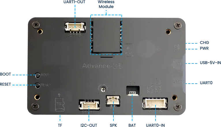
1 Introduce product ports
USB interface: used for power supply, serial communication, and automatic programming.
UART0-IN interface: supports power supply, serial communication, and entering manual burning mode by pressing BOOT+RESET; Other functions are consistent with the USB interface.
UART0-OUT interface: used for external power supply and serial communication.
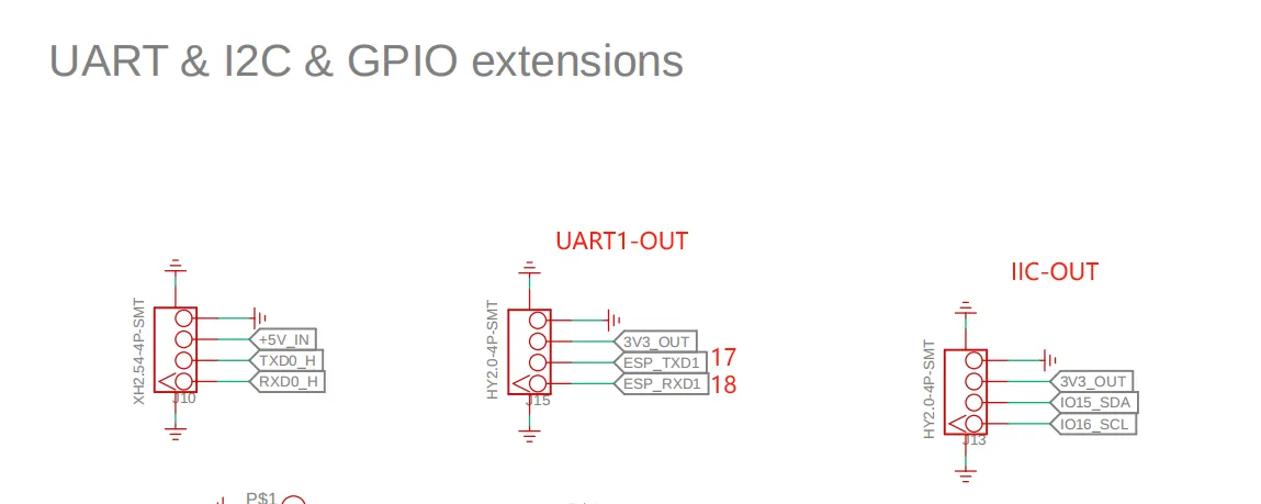
UART1-OUT interface: uses soft serial port and supports configuring IO function.
I2C-OUT interface: connects RTC chip, extended IO chip (for screen backlight, touch screen reset, power amplifier pin control) and wireless module, only supports I2C communication.
2 Taking UART1-OUT interface and IIC-OUT as examples
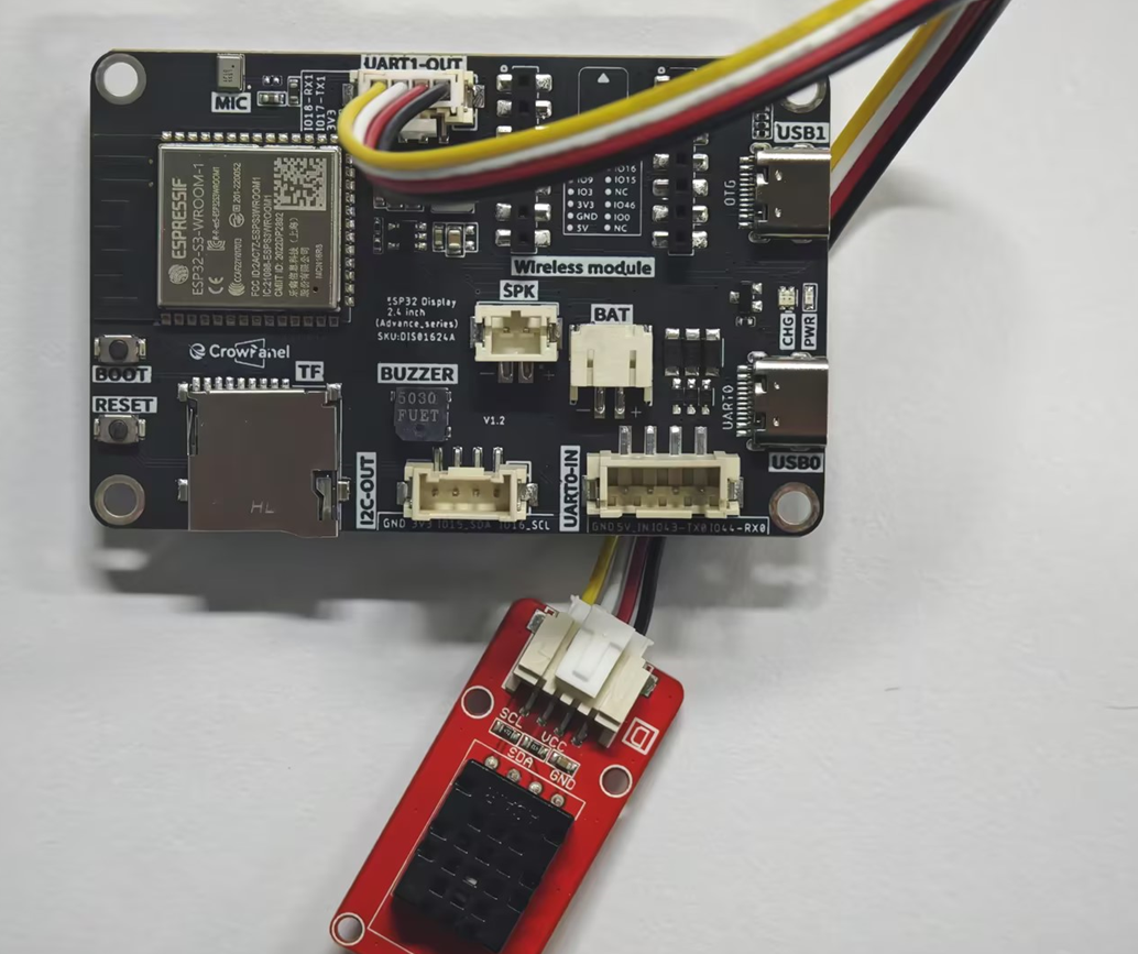
Next, taking the external light bulb connected to the UART1-OUT interface and the temperature and humidity sensor connected to the IIC-OUT interface as an example. The temperature and humidity sensor needs to support IIC communication. The peripherals connected to the IIC interface are all like this.
In order to provide everyone with an intuitive observation, I will use LVGL to create an interactive interface.
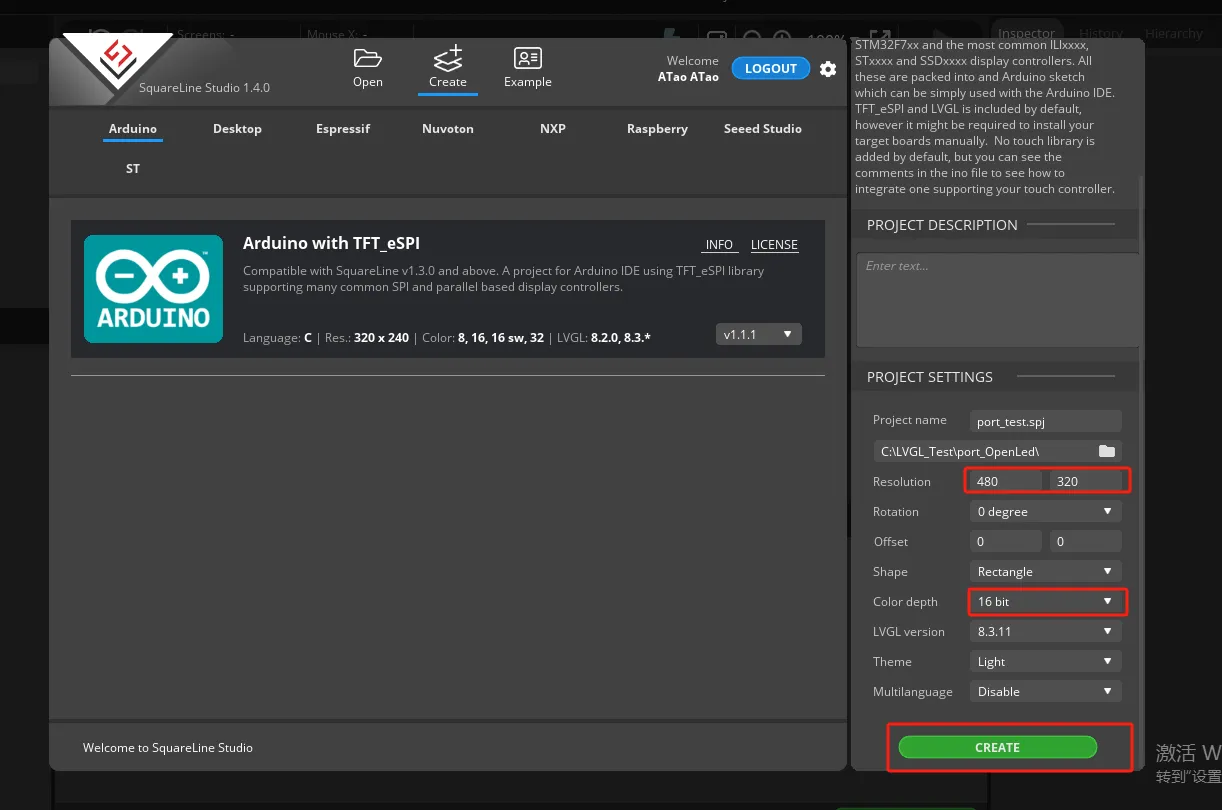
Open SquareLine Studio. If you haven't installed it, you can review the introduction of LVGL in Lesson 3.

Create Arduino project
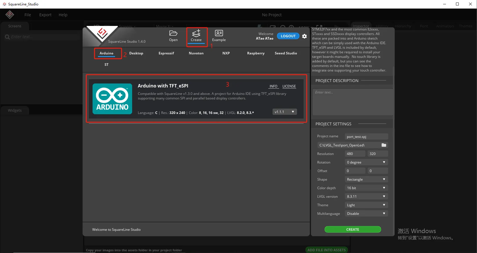
Modify the file name and file storage path according to your needs (customization is sufficient)
If you are using a 2.8 / 2.4 inch product, please change the resolution to 320*240.
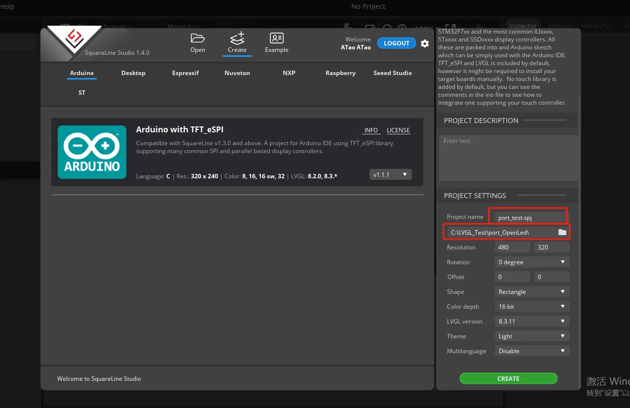
Modify the appropriate resolution based on the different sizes you are using.
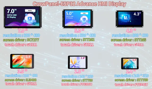
If you are using a 2.8 / 2.4 inch product, please change the resolution to 320*240.
Finally, click on 'Create' to proceed.
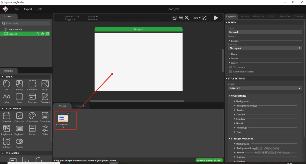
Add the background image we provide based on the resolution required for the size you are using (choose different resolutions for different sizes, refer to the resolution size used for different sizes in Lesson 3)
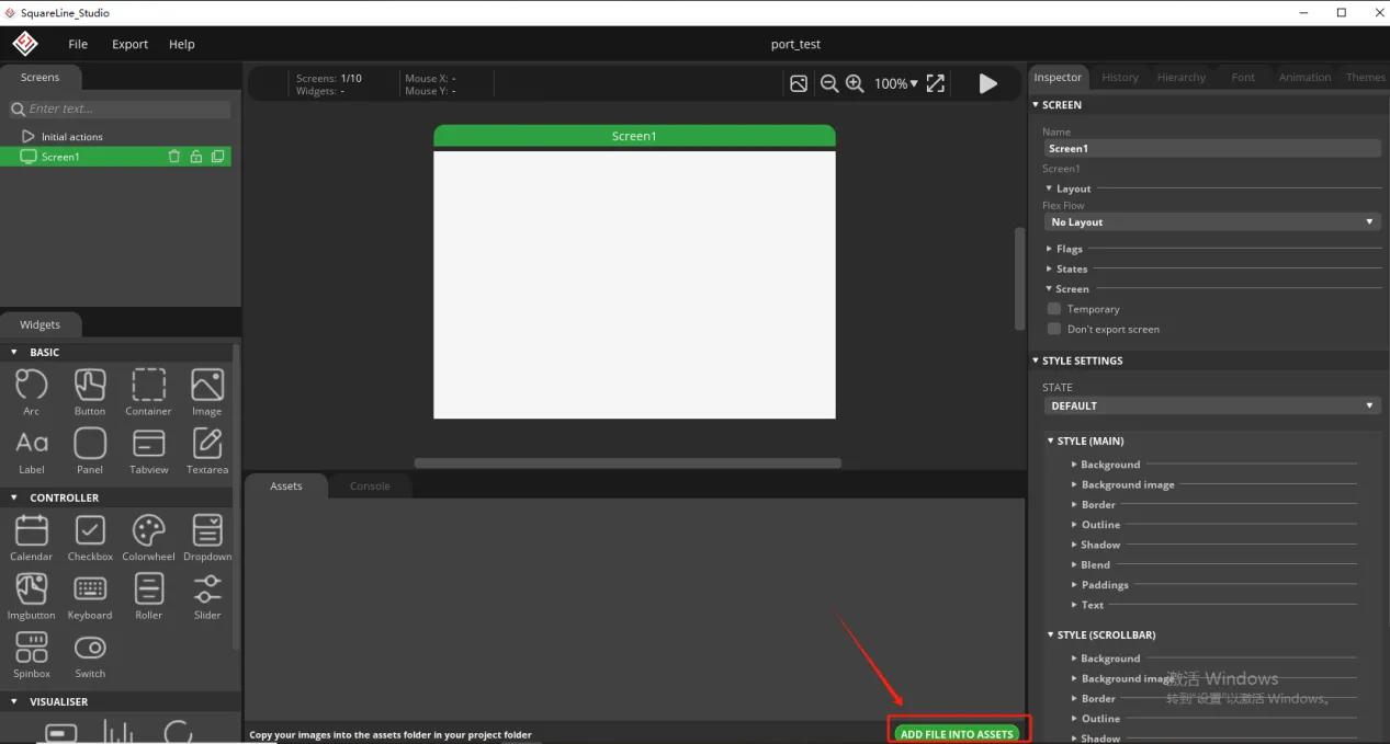
Click the link below to download the supporting images for this lesson.
Resource link:
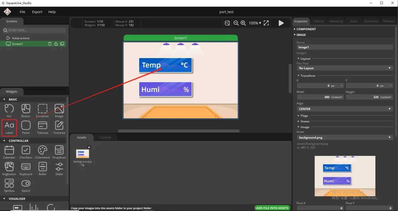
Add background image to the box.
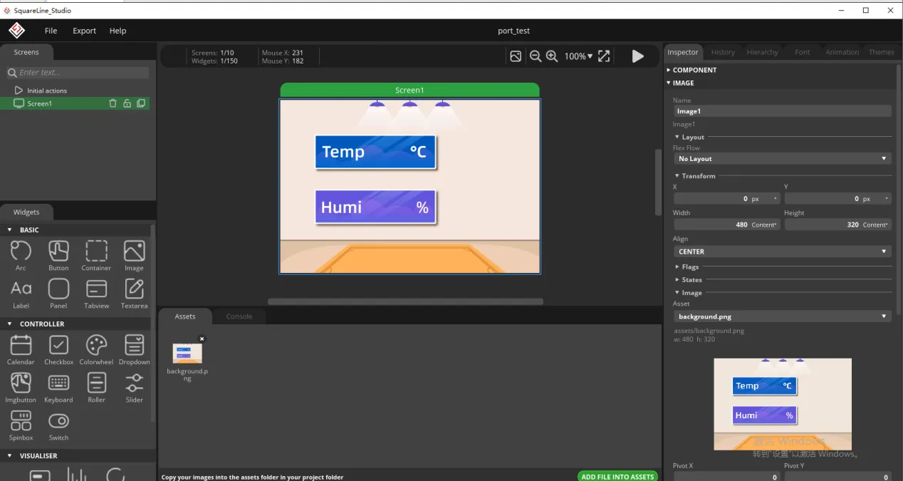
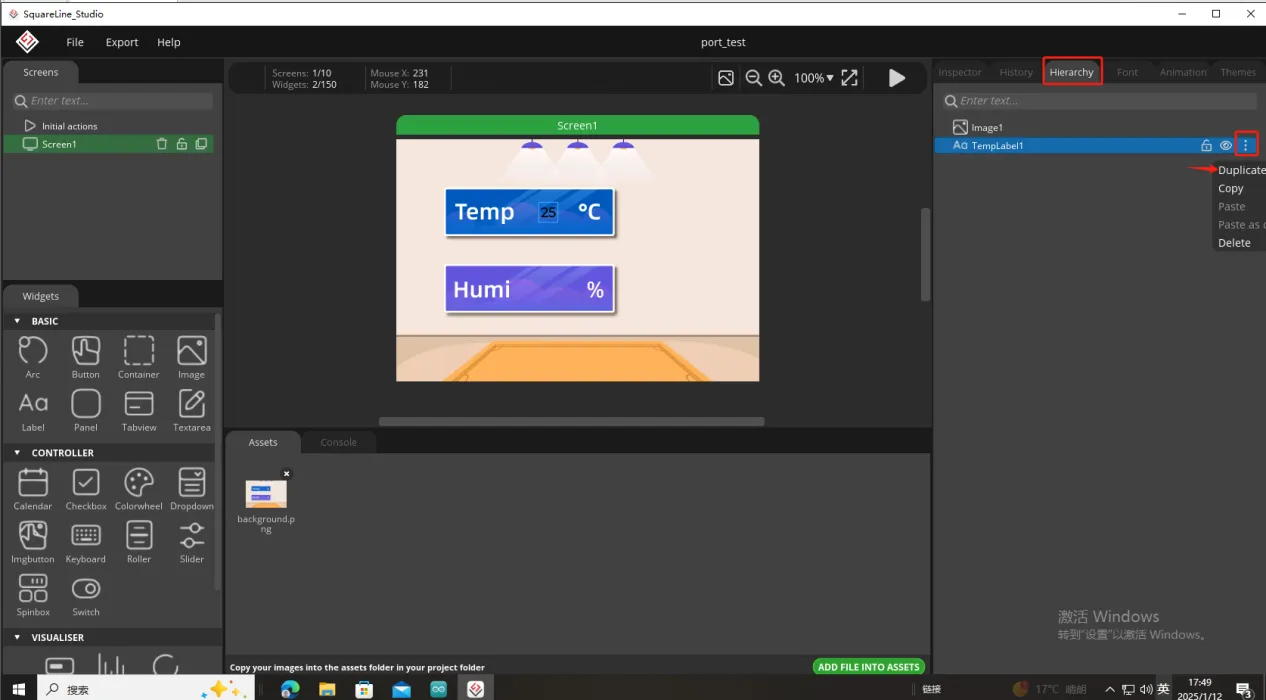
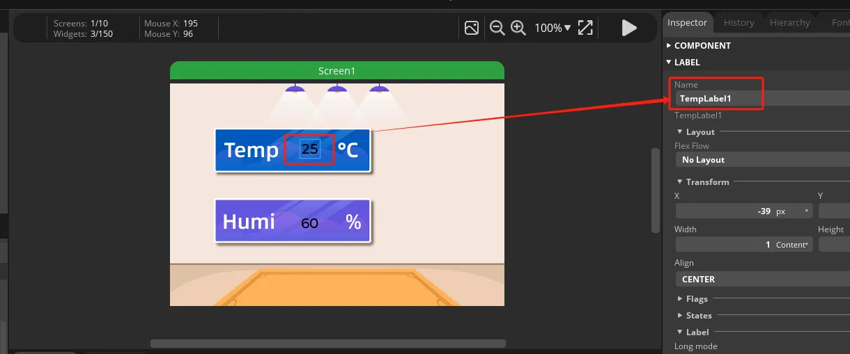
Since we need to display the temperature and humidity values on the screen, we need to add text in the two boxes for temperature and humidity.
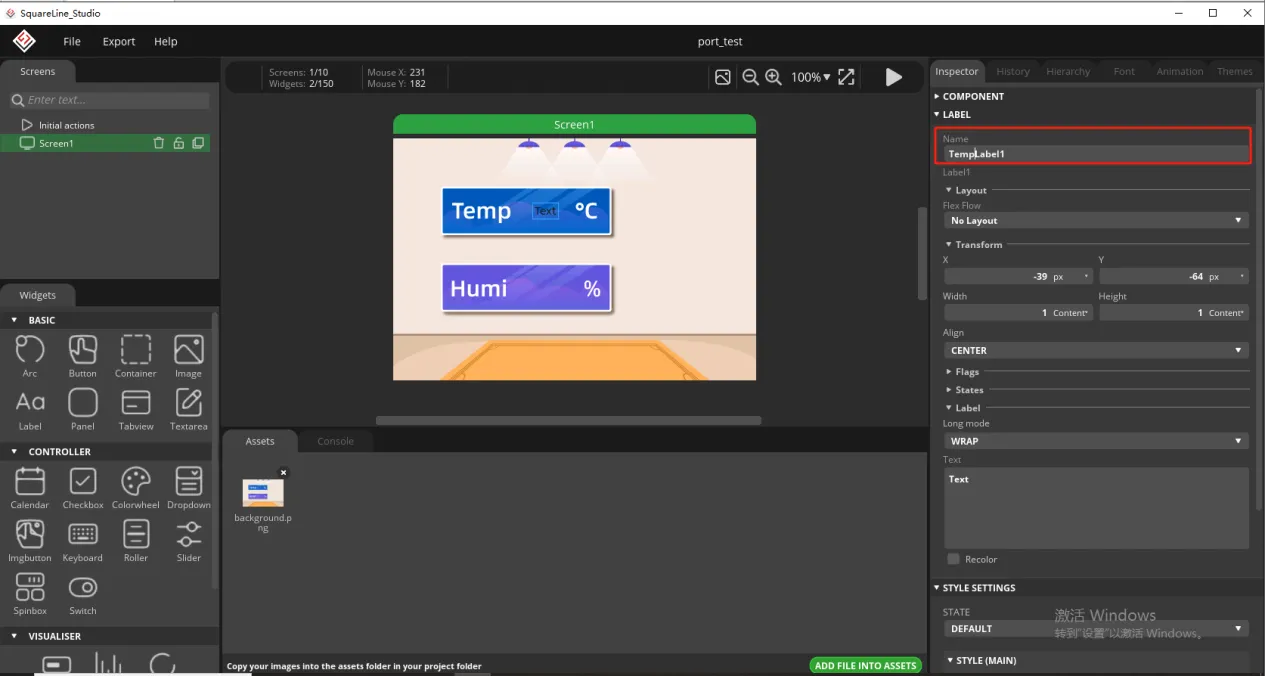
To distinguish between the other text labels that need to be created next, give this label a name to distinguish it.
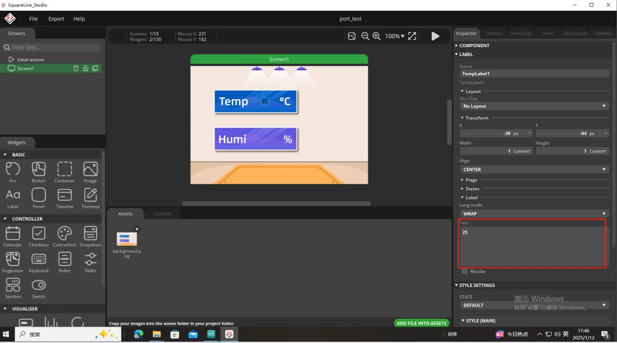
And fill in a default temperature value
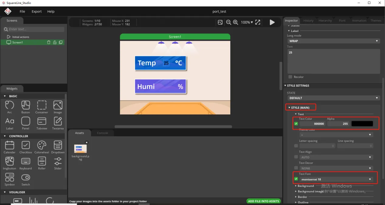
Of course, you can also set the font color and font size here
Copy the label just made and display the humidity value
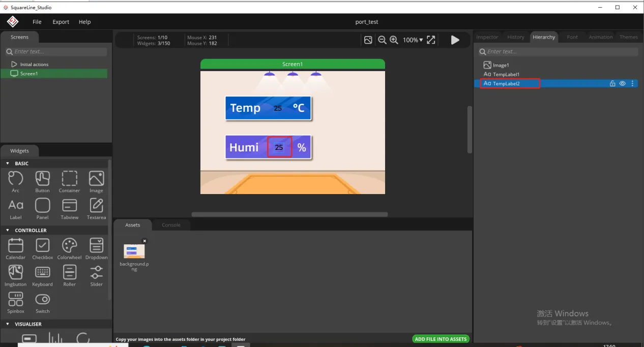
Follow the above steps to modify the humidity label
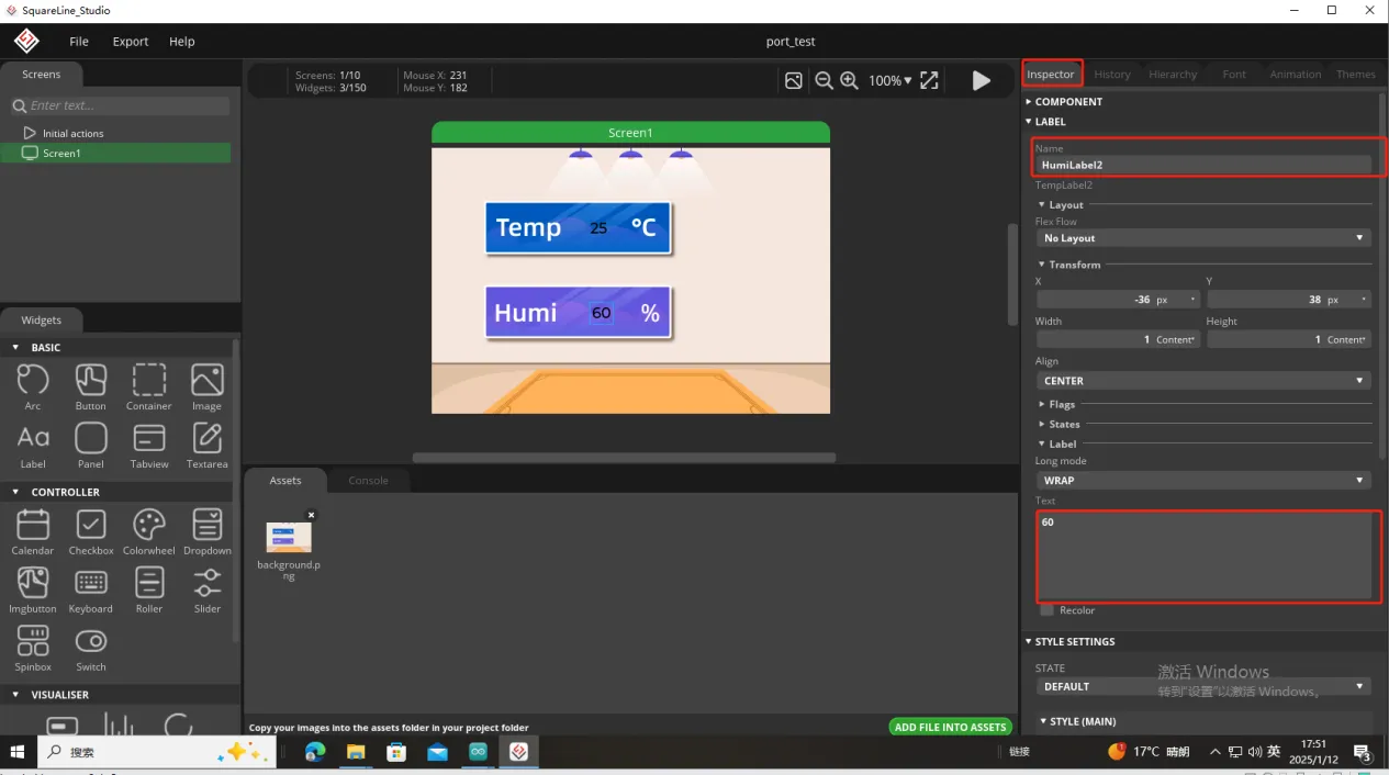
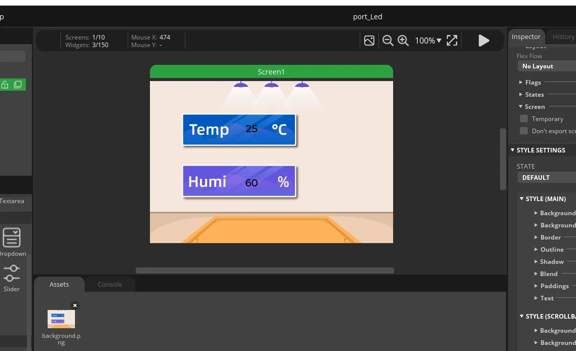
In this way, the display of temperature and humidity is completed.
So, the UI interface we need is completed.
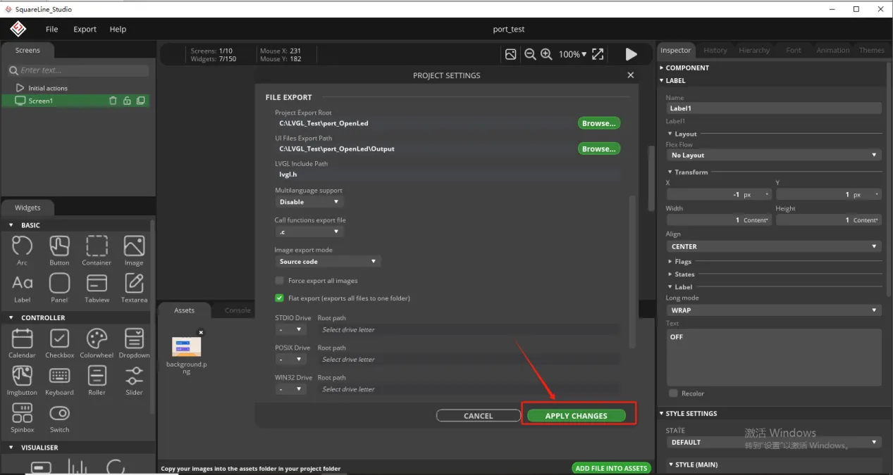
Click on Project Setting
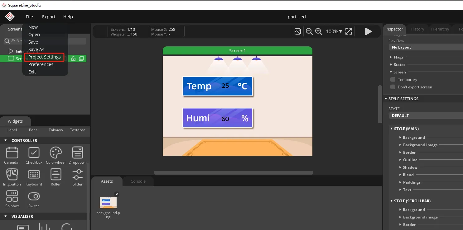
Set the file export path and customize the path
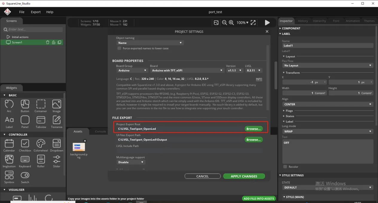
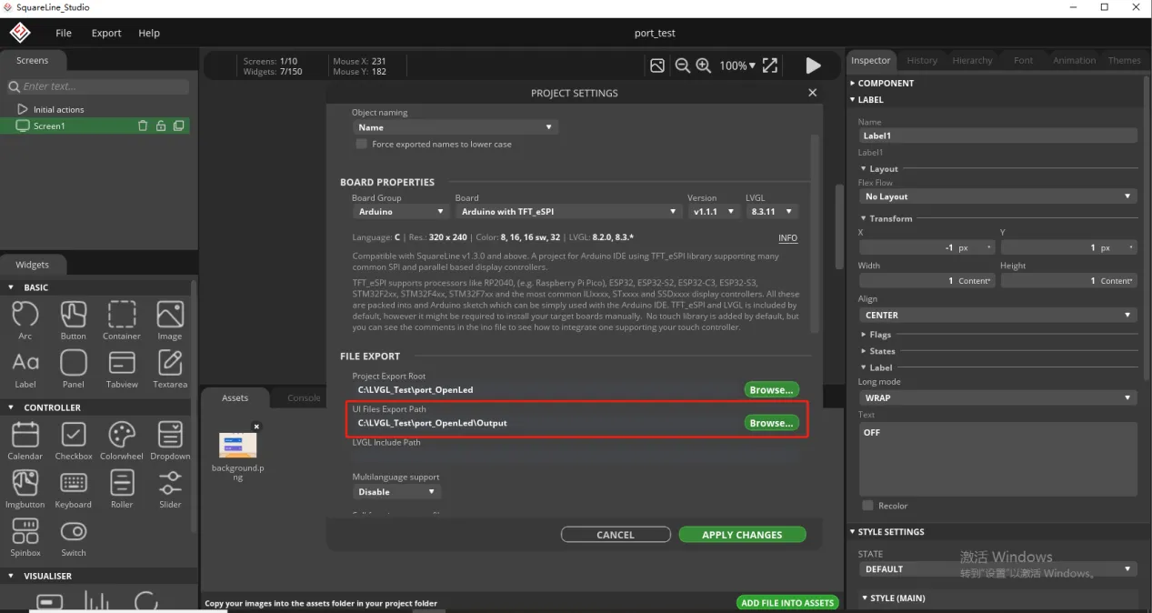
But here, you need to create an Output folder in the path above to receive the exported UI files.
Fill in lvgl. h and select Flat export.
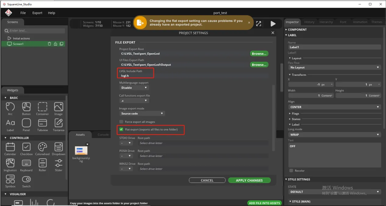
Finally confirm the settings
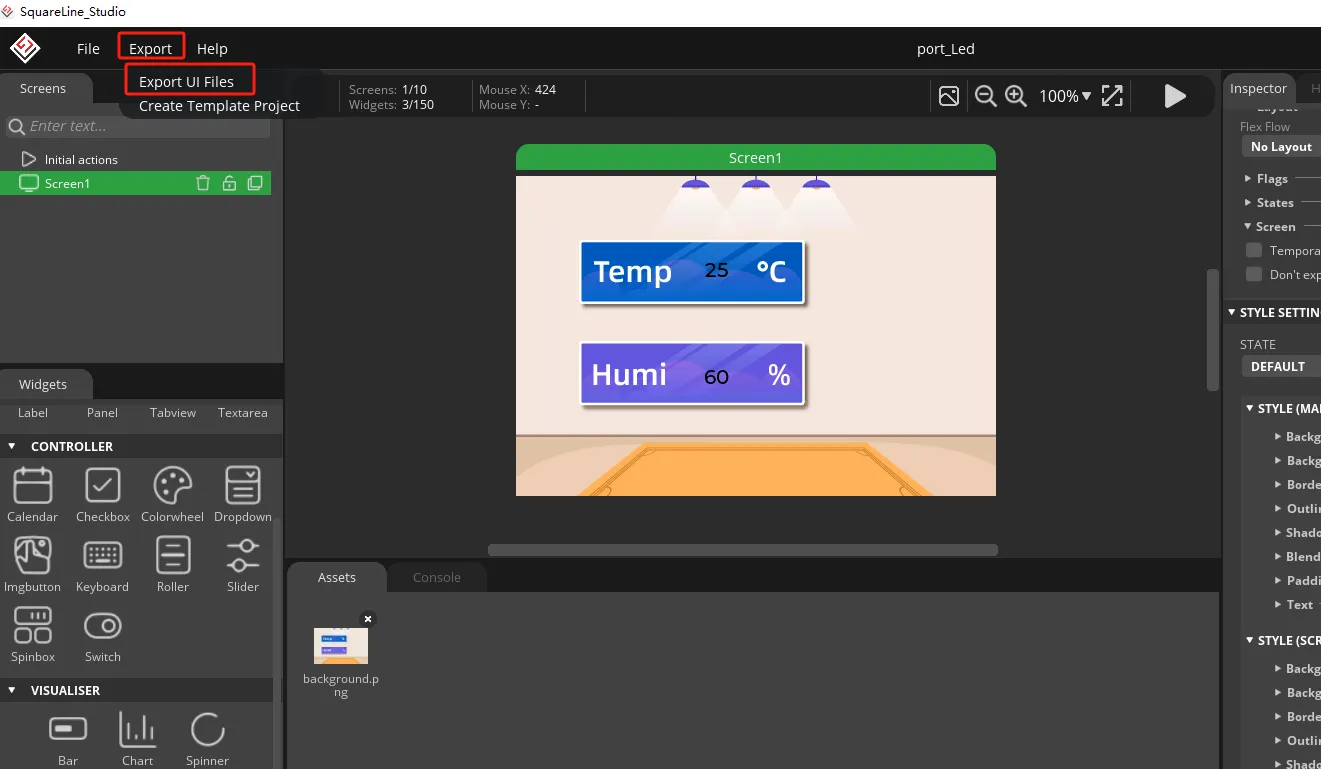
Export the designed UI interface file
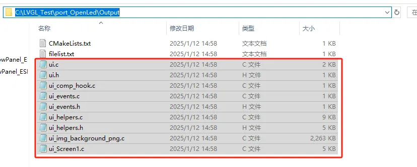
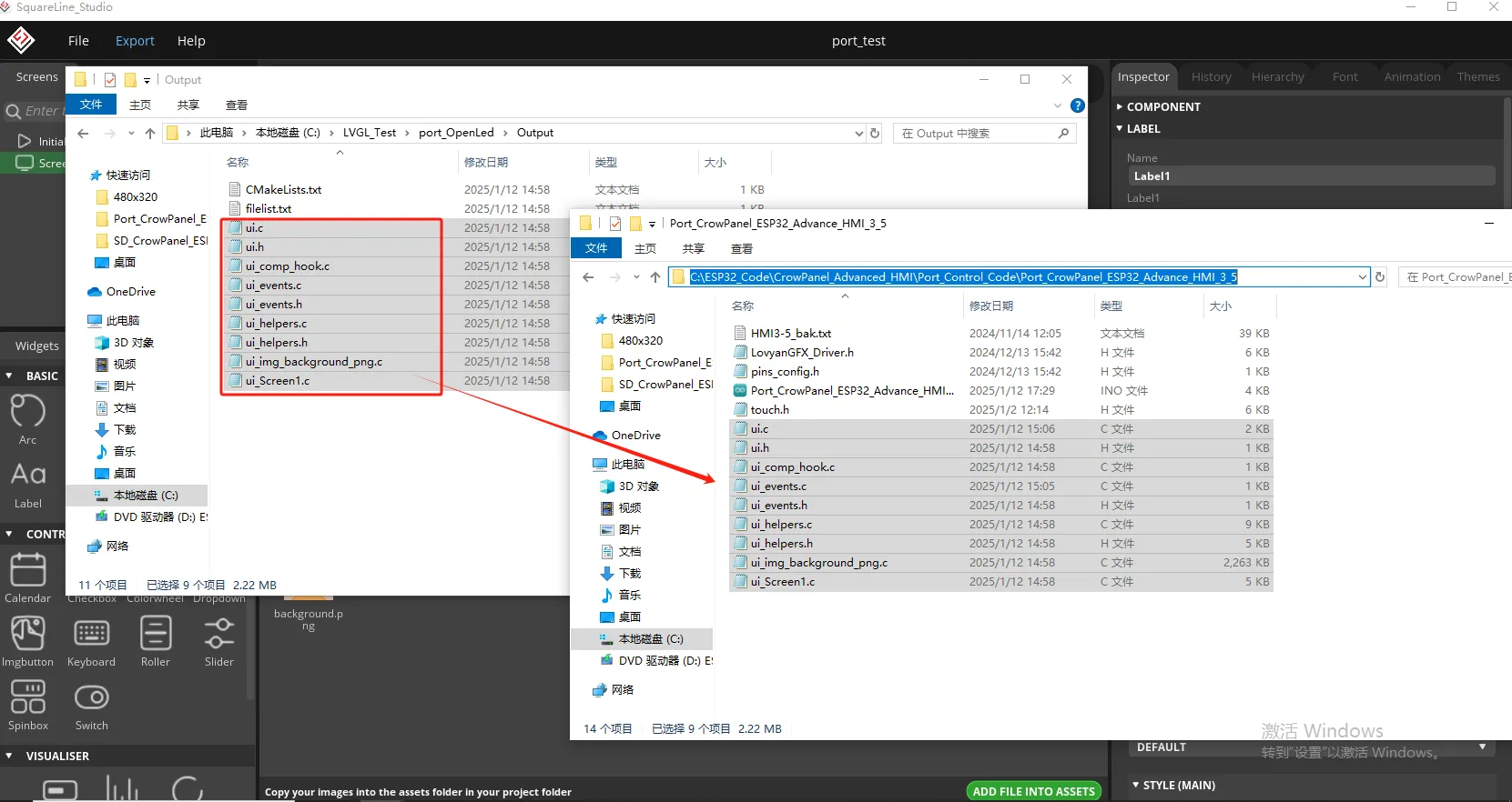
Go to the Output folder you just set up and copy the UI files you generated.
Paste it into the code file you need to open (here I will introduce the 3.5-size code as an example).
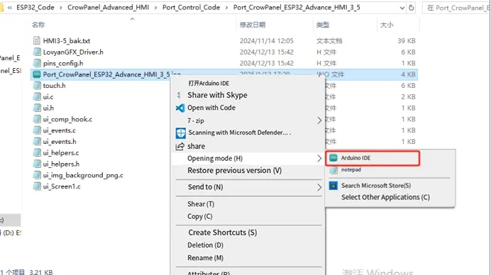
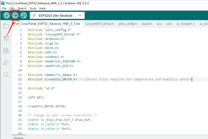
Then use Arduino IDE to open the ino file in the folder
3 Code Explanation
You can click the link below to download the corresponding version of the code for this lesson. Code link:
2.8-inch / 2.4-inch V1.0:
2.8-inch / 2.4-inch V1.1/V1.2:
Introduce several key points in the code
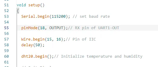
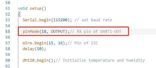
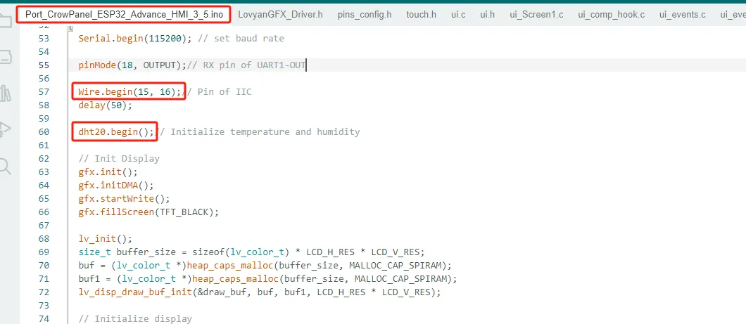
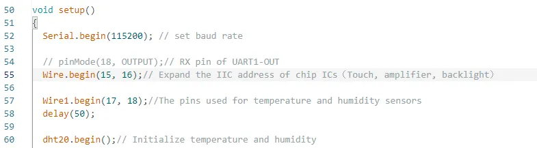
Initialize UART1-OUT pin, IIC pin, and temperature and humidity sensor
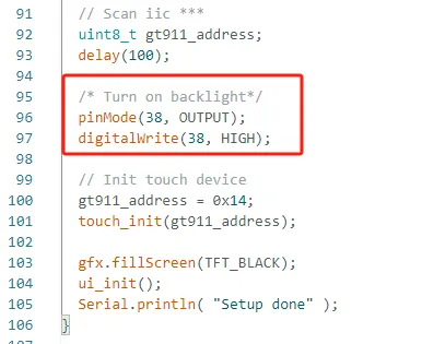
Turn on the screen backlight to enable the screen to display
Previously, pin 18 was set as the output mode, and the UART1-OUT interface was connected to the light bulb. By controlling pin 18, the light can be controlled.
The brightness and darkness of bubbles.
Because the temperature and humidity sensor is connected to the IIC interface, it is necessary to initialize pins 15 and 16 of the IIC and initialize the temperature and humidity sensor.
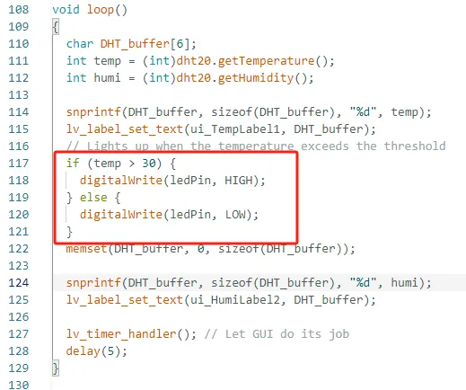
And define two variables to receive data collected by temperature and humidity sensors
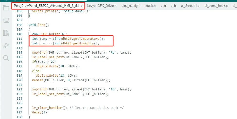
And display the value on the label you previously designed

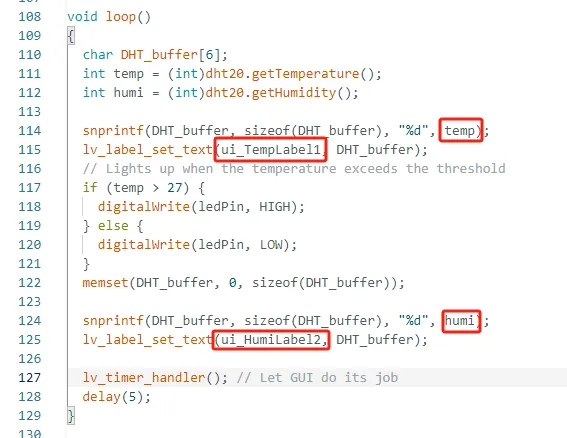
If the temperature value collected by your temperature and humidity sensor exceeds 30 ℃, the light bulb will automatically light up; If the temperature drops below 30 ℃, the light bulb will automatically turn off. (You can modify the temperature threshold yourself, this is only for the convenience of observing the results)
If you are using the 2.4-inch or 2.8-inch model, you do not need to connect the LED to the UART1-OUT port. For these models, the UART1-OUT interface is reserved for the temperature and humidity sensor used in this project, so the LED is not connected. The reason for this hardware arrangement will be explained in the following section.
Special Reminder:
(The following applies only to 2.8-inch and 2.4-inch products)
If you are using the 2.8-inch or 2.4-inch version of the product, you need to pay special attention to the issue of IIC device address conflicts. The IIC address of the onboard touch driver chip is 0x38, and the default IIC address of the DHT20 temperature and humidity sensor is also 0x38. When you connect the DHT20 temperature and humidity sensor to the IIC-OUT interface, since both devices use the same IIC address, an address conflict will occur, resulting in the devices being unable to communicate normally. In this situation, the system will give priority to ensuring the normal operation of the touch driver chip. Therefore, the touch function will not be affected, but the DHT20 temperature and humidity sensor will be unable to read data properly. To solve this problem, we suggest connecting the DHT20 temperature and humidity sensor to the UART1-OUT interface for use. This will prevent IIC address conflicts and ensure that the temperature and humidity sensor can operate normally. Additionally, it is important to note that the UART1-OUT interface actually provides two GPIO pins (IO17 and IO18) that are available for user use. You can use them as regular GPIOs and connect some peripherals that only require one or two IO pins.
For example, when connecting an LED light, IO18 can be used as the control pin, and the on/off state of the light can be controlled by the program.
It should be noted that the UART1-OUT interface only provides two GPIO pins, namely IO17 and IO18. Therefore, it is only suitable for peripheral devices that occupy a relatively small amount of IO resources. If certain modules require the use of more GPIO pins, such as SPI devices which typically need multiple signal lines including SCK, MOSI, MISO and CS, then they cannot be directly connected and used through the UART1-OUT interface.
2.4" 2.8"
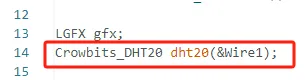
And when initializing the temperature and humidity sensor, specify the IIC pin used for initializing the temperature and humidity sensor.
Use
Wire1(GPIO17 for SDA and GPIO18 for SCL).
4 Hardware connection
For the 2.4-inch and 2.8-inch versions of the product, since there is an IIC address conflict between the onboard touch driver chip and the DHT20 temperature and humidity sensor, this tutorial uses the UART1-OUT interface to connect the DHT20 temperature and humidity sensor.
During actual use, we reconfigured IO17 and IO18 as IIC communication pins, with one serving as SDA (data line) and the other as SCL (clock line), thus enabling communication with the DHT20 temperature and humidity sensor. This not only ensures the normal operation of the touch function but also allows for the normal reading of temperature and humidity data.
5 Configure the environment, upload code, and view phenomena
(Before uploading the code, please replace the relevant library files. Please refer to Lesson 1 for instructions on how to replace them.)
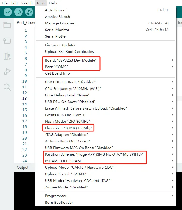
Configure the operating environment according to the guidance.
Upload code
Phenomenon display

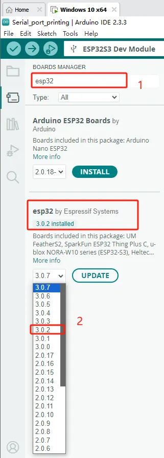
If your code compiles incorrectly, you can check if the ESP32 version number is correct. The ESP32 version number we need for this lesson is 3.0.2.
Secondly, please pay attention to replacing the corresponding size library file.
Select the appropriate library file based on the product screen size
Click the link below to download the relevant library files.
Library file link:
If you are not sure where to place the library files and how to configure them properly so that the code can correctly recognize these library files, please refer to the operation steps in the first lesson.