CrowPanel 2.01inch HMI ESP32 Watch Display 240x296 IPS Touch Screen With Microphone Supports Voice Control(No Enclosure/Strap)
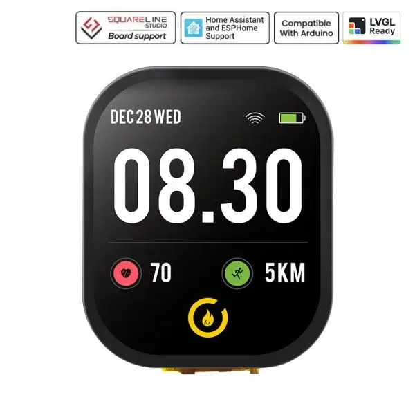
1.Information on Hardware Interfaces:
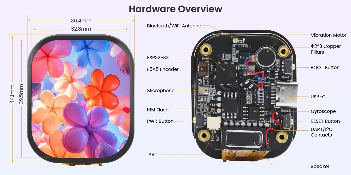
CrowPanel 2.01inch-HMI ESP32 Watch Display Wiring Pins:
SPI (Serial Peripheral Interface) display mode is a communication method that connects an MCU to a display via a serial bus. It requires only a small number of GPIO pins for data transmission and features a simple hardware connection.
The SPI interface is suitable for small- and medium-sized TFT, OLED, and LCD displays. It offers good compatibility, a well-established development ecosystem, and low cost; however, due to bus bandwidth limitations, its refresh rate is typically lower than that of parallel display interfaces such as RGB and MIPI DSI.
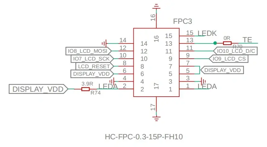
SPI Pin connection
constexpr uint8_t PIN_LCD_POWER = 40;        // Use GPIO40 to control the LCD power rail.
constexpr uint8_t PIN_PERIPHERAL_POWER = 47; // Use GPIO47 to enable the shared peripheral power rail.
constexpr uint8_t PIN_LCD_BACKLIGHT = 13;    // Use GPIO13 as the LCD backlight PWM output.
constexpr uint8_t PIN_LCD_TE = 21;           // Use GPIO21 for the LCD tearing-effect synchronization signal.
constexpr uint8_t PIN_LCD_RST = 6;           // Use GPIO6 for the GC9309 LCD reset signal.
constexpr uint8_t PIN_LCD_DC = 10;           // Use GPIO10 for the LCD data/command signal.
constexpr uint8_t PIN_LCD_CS = 9;            // Use GPIO9 for the LCD chip-select signal.
constexpr uint8_t PIN_LCD_SCK = 7;           // Use GPIO7 for the LCD SPI clock signal.
constexpr uint8_t PIN_LCD_MOSI = 8;          // Use GPIO8 for the LCD SPI MOSI data signal.
constexpr int8_t PIN_LCD_MISO = -1;          // Set MISO to -1 because the LCD write path does not use MISO.
ESP32-S3 and Touch Driver Wiring:
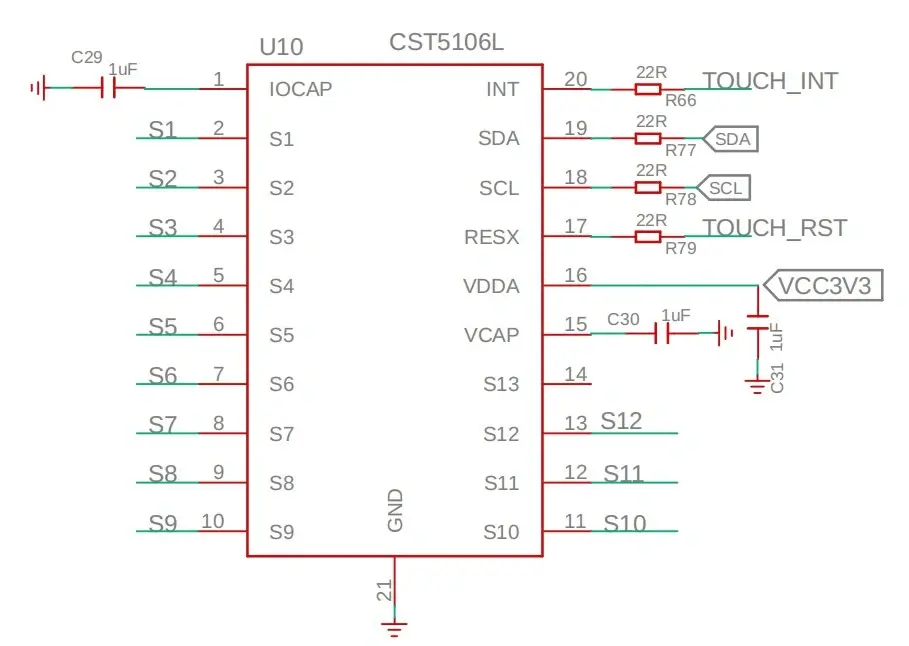
Pin connection
constexpr uint8_t PIN_I2C_SCL = 3;        // Use GPIO3 as the shared I2C clock pin from the reference project.
constexpr uint8_t PIN_I2C_SDA = 4;        // Use GPIO4 as the shared I2C data pin from the reference project.
constexpr uint8_t PIN_TOUCH_INT = 2;      // Use GPIO2 for the AXS5106L interrupt signal.
constexpr uint8_t PIN_TOUCH_RST = 5;      // Use GPIO5 for the AXS5106L reset signal.
ESP32-S3 and MIC wiring pins:
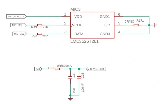
Pin connection
constexpr uint8_t kMicrophoneClockPin = 12;              // Use GPIO12 as the PDM microphone clock pin.
constexpr uint8_t kMicrophoneDataPin = 11;               // Use GPIO11 as the PDM microphone data pin.
constexpr uint8_t kPeripheralPowerPin = 47;              // Use GPIO47 to enable the shared peripheral power rail.
ESP32-S3 and Audio out:
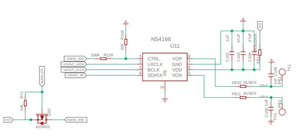
Pin connection
constexpr uint8_t kAudioEnablePin = 48;     // Use GPIO48 to enable or mute the speaker amplifier.
constexpr uint8_t kI2sDataPin = 41;         // Use GPIO41 as the I2S speaker data output.
constexpr uint8_t kI2sBclkPin = 42;         // Use GPIO42 as the I2S bit clock.
constexpr uint8_t kI2sLrclkPin = 46;        // Use GPIO46 as the I2S left/right word clock.
constexpr uint8_t kPeripheralPowerPin = 47; // Use GPIO47 to enable the shared peripheral power rail.
ESP32-S3 and GYRO:
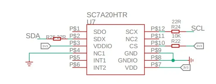
constexpr uint8_t kI2cSdaPin = 4;         // Use GPIO4 as the watch I2C SDA pin.
constexpr uint8_t kI2cSclPin = 3;         // Use GPIO3 as the watch I2C SCL pin.
constexpr uint8_t kSensorAddress = 0x19;  // Use the validated SC7A20H I2C address.
ESP32-S3 and RTC:

RTC shares the same I2C bus with Touch and Accelerometer
constexpr uint8_t kI2cSdaPin = 4;       // Use GPIO4 as the watch I2C SDA pin.
constexpr uint8_t kI2cSclPin = 3;       // Use GPIO3 as the watch I2C SCL pin.
Rotary Encoder:

constexpr uint8_t kEncoderPinA = 20;           // Use GPIO20 for encoder phase A.
constexpr uint8_t kEncoderPinB = 19;           // Use GPIO19 for encoder phase B.
constexpr uint8_t kEncoderButtonPin = 18;      // Use GPIO18 for the active-low encoder push button.
constexpr uint8_t kBootButtonPin = 0;          // Select GPIO0, the active-low BOOT button on the ESP32-S3 module.
2.Platforms Supported
Please click the card below and follow the instructions to install Arduino and ESP-IDF.
Arduino link:https://www.elecrow.com/wiki/Get_Started_with_Arduino_IDE.html
ESP-IDF link: https://www.elecrow.com/wiki/Get_Started_with_ESP-IDF.html
Courses on Different Platforms:
| Arduino | ESP-IDF |
|---|---|
 |  |
| Arduino IDE View Tutorials -- V1.0 | ESP-IDF View Tutorials -- V1.0 |
3.Resources
Github link:
(This GitHub link usually may contain 3D files, schematics, program code, factory firmware, factory sourcecode and other materials. Please click to view.)
4.How to buy
Please visit this page to purchase CrowPanel 2.01inch HMI ESP32 Watch Display.
5.Support
If you encounter any issues while using the product, you can contact us via the social media links in the bottom-right corner of elecrow or send an email to techsupport@elecrow.com for technical support.