The First Lesson: Installation and Configuration of IDF-IDE and Printing "Hello World" via Serial Port
1. Product Introduction
1.1 product overview
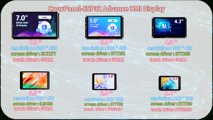
The CrowPanel-ESP32 Advance HMI Display product is divided into 6 sizes, namely 7.0 inches, 5.0 inches, 4.3 inches, 3.5 inches, 2.8 inches, and 2.4 inches.Its main control chip uses ESP32-S3 as the core of the man-machine interface.
The resolution of the 7.0-inch display screen is 800 * 480, the screen driver chip is SC7277, and the touch driver chip is GT911;
5.0-inch display screen resolution of 800 * 480, screen driver chip ST7262, touch driver chip GT911;
4.3-inch display screen resolution of 800 * 480, screen driver chip ST7265, touch driver chip GT911;
3.5-inch display screen resolution of 320 * 480, screen driver chip ILI9488, touch driver chip GT911;
2.8-inch display screen resolution of 240 * 320, screen driver chip ST7789, touch driver chip FT6336U;
2.4-inch display screen with a resolution of 240 * 320, screen driver chip ST7789, and touch driver chip FT6336U.
Which combines powerful processing capabilities, diverse peripheral interfaces, and excellent low-power performance. Its integrated 2.4GHz Wi Fi and Bluetooth 5 (LE), combined with the module's built-in RF antenna, ensure the stability of wireless connection, especially suitable for HMI application scenarios with high requirements for wireless connection.
1.2 Hardware feature
After understanding the optimization of the product, let's take a closer look at the hardware changes.
For 4.3-inch, 5.0-inch, and 7.0-inch screens, they only have one USB interface that can be used for code burning, etc.
For 2.4-inch, 2.8-inch, and 3.5-inch, there are two USB ports here. When using the USB port for code burning, you need to first hold down the BOOT button, then press the RESET button, and then release them together to burn the code; The UART0 interface allows for direct code burning without the need to press any buttons.

Attention: For the three sizes of 2.4 inches, 2.8 inches, and 3.5 inches, USB OTG function is also available.
The USB OTG function of ESP32-S3 supports switching between host and device roles, allowing for the connection of peripherals such as keyboards, mice, USB drives, or as USB peripherals (such as virtual serial ports, HID devices) to communicate with the host. It is suitable for scenarios such as data transmission, peripheral control, debugging interfaces, custom USB devices, etc. It has high flexibility and simplifies IOT and embedded development.
For 3.5-inch, 4.3-inch, 5.0-inch, and 7.0-inch products, RTC circuits have been added to ensure the continuity and accuracy of system time in the event of a power outage, providing a reliable time reference for data recording and event monitoring.
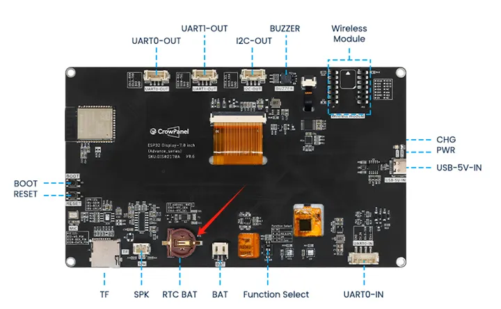
Secondly, this wireless module can be used for communication and data transmission. It supports 802.11 a/b/g/n wireless communication standards, WiFi in the 2.4GHz frequency band, as well as low-power Bluetooth and Bluetooth 5.0, and also supports Zigbee NBIOT、LoRa、UWB、NF2401.

There are also some other interfaces and peripherals available for everyone to use. For example, the I2C interface can be used for sensor devices suitable for using I2C communication; UART0 interface, suitable for sensor devices that use serial communication; SD card slot, capable of meeting local storage requirements; Speaker interface, capable of connecting external speakers for playing songs, etc; Battery interface, which can be used for external battery power supply.
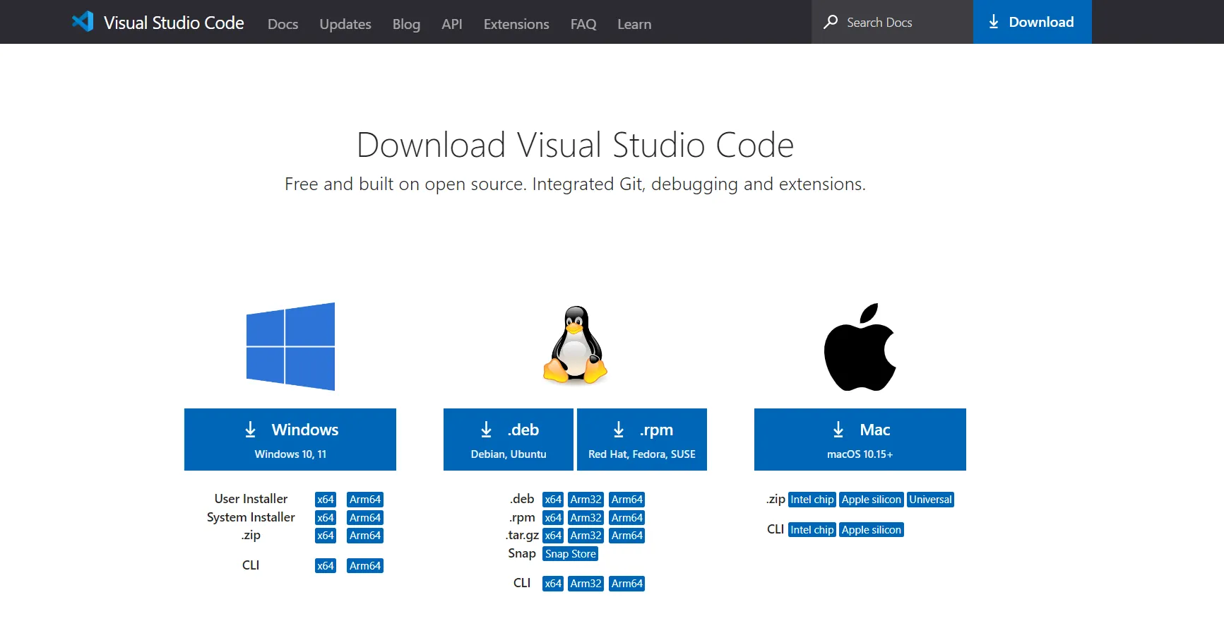
2. Download Visual Studio Code
Search for Visual Studio Code download on Google or enter the https://code.visualstudio.com/download, select the version compatible with your computer system and download Visual Studio Code installer. In this instructions we are selecting Windows.
Double-click the "VSCodeUserSetup" file to install the Visual Studio Code.
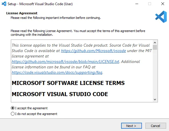
Accept the license agreement and go next.
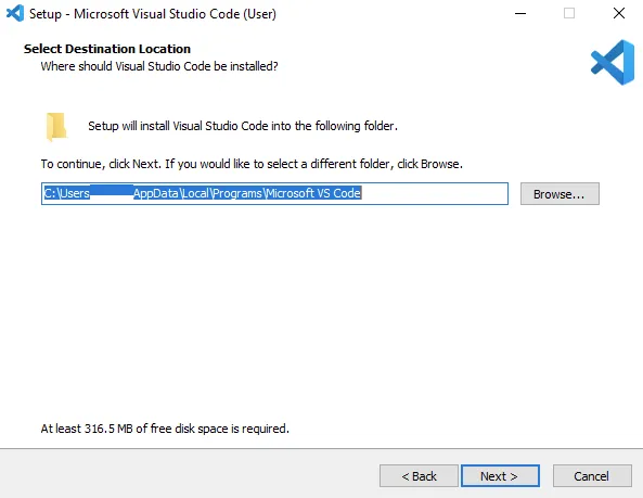
Accept the default location or click "Browse..." to change the installation location.
Accept the resting default option and click "Next >"
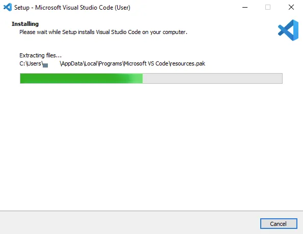
Click install and waiting for the installation ...
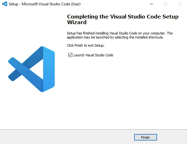
Click "Finish" to exit the installation and (by default) launch Visual Studio Code:
Open Visual Studio Code and open Extension Manager.
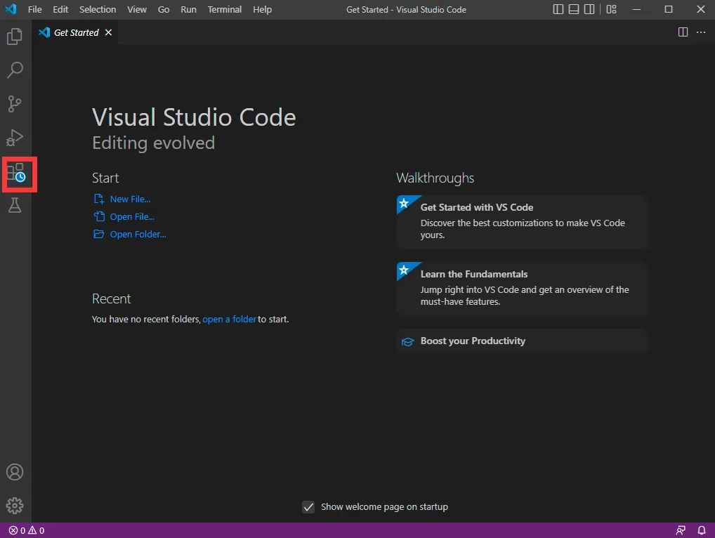
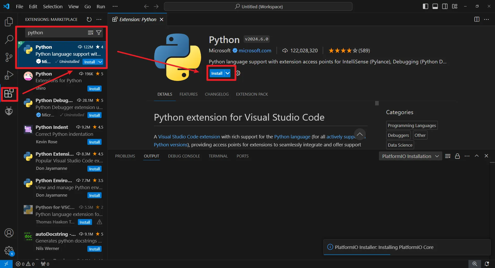
3. Install Python
Search for "Python" and install.
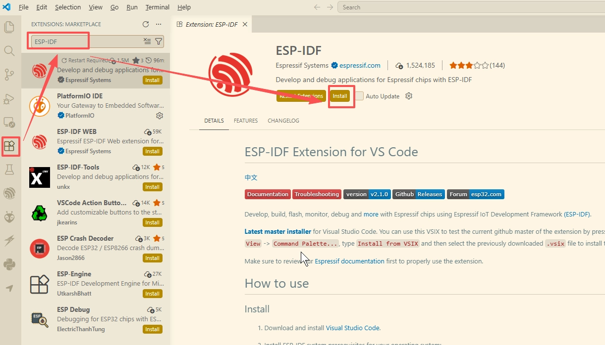
4. Install ESP-IDF
Search for "ESP-IDF" and install
After ESP-IDF is installed, launch the ESP-IDF Tools Manager
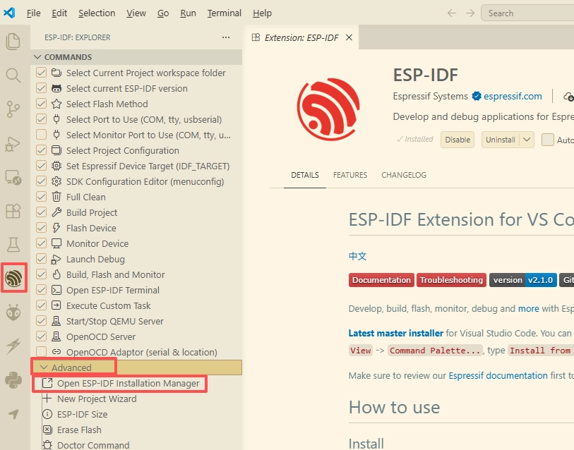
Select Custom Installation
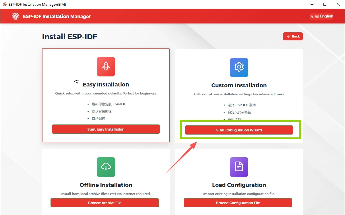
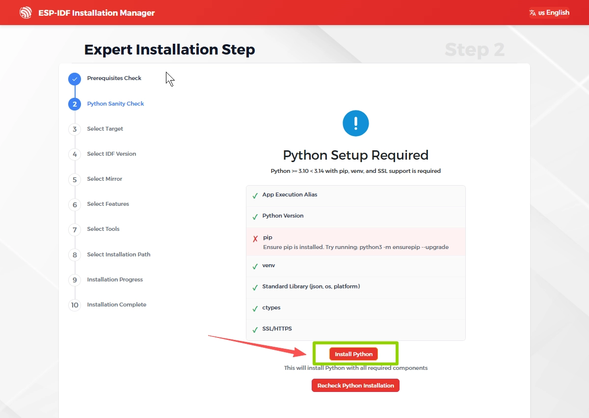
After entering, the installer will automatically check whether your system meets the requirements for installing ESP-IDF.
If any required components are missing, click "Install Python" to install the necessary environment
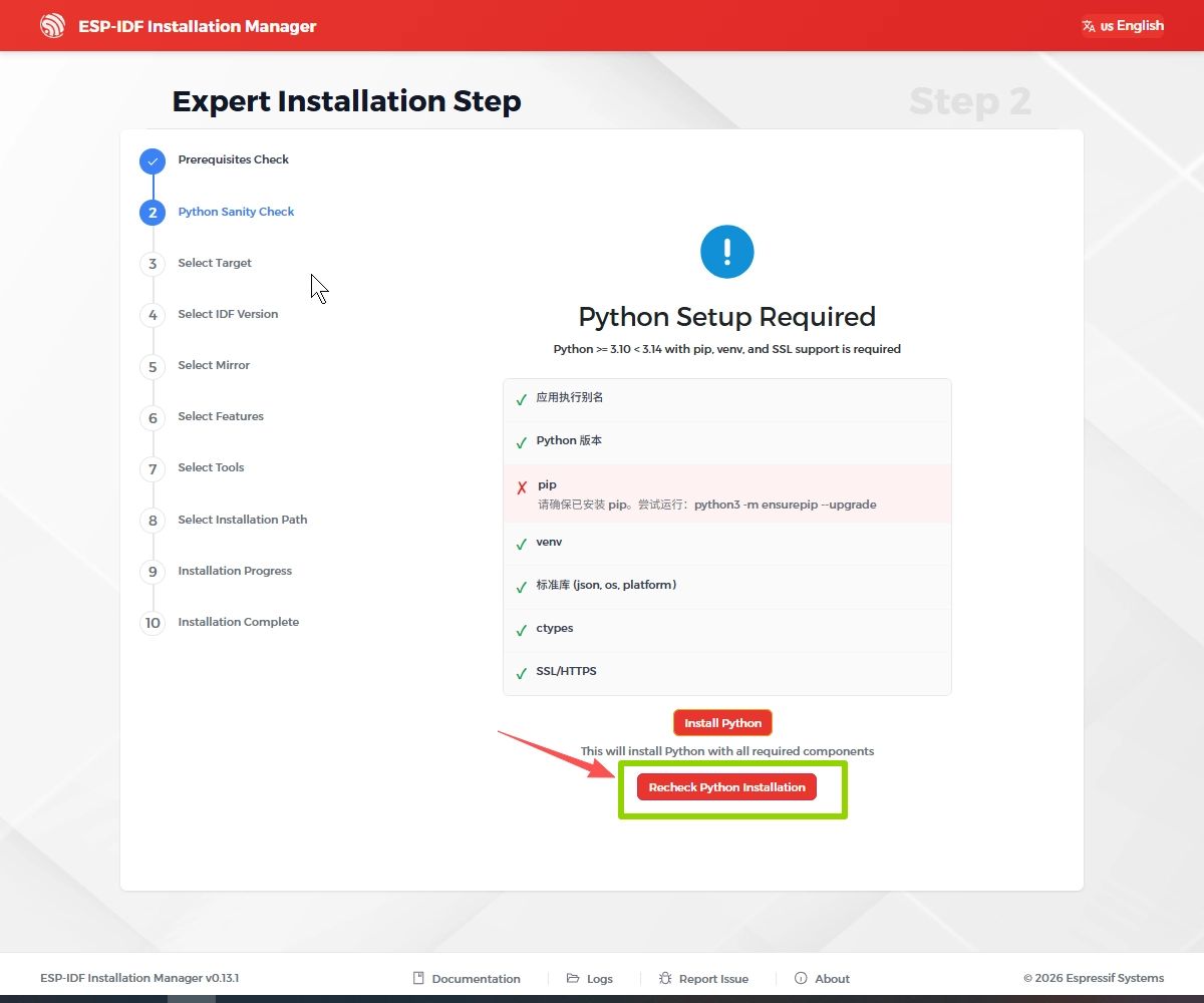
After the installation is complete, click it again to recheck whether the environment meets the requirements
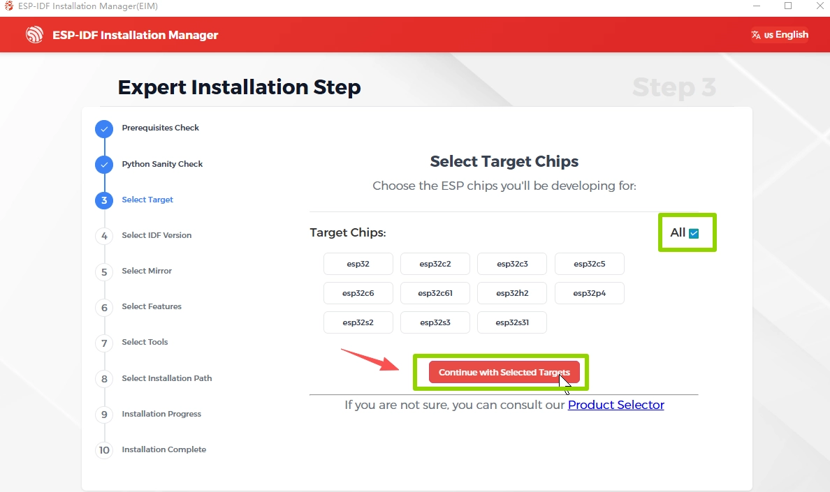
Select Target Chips
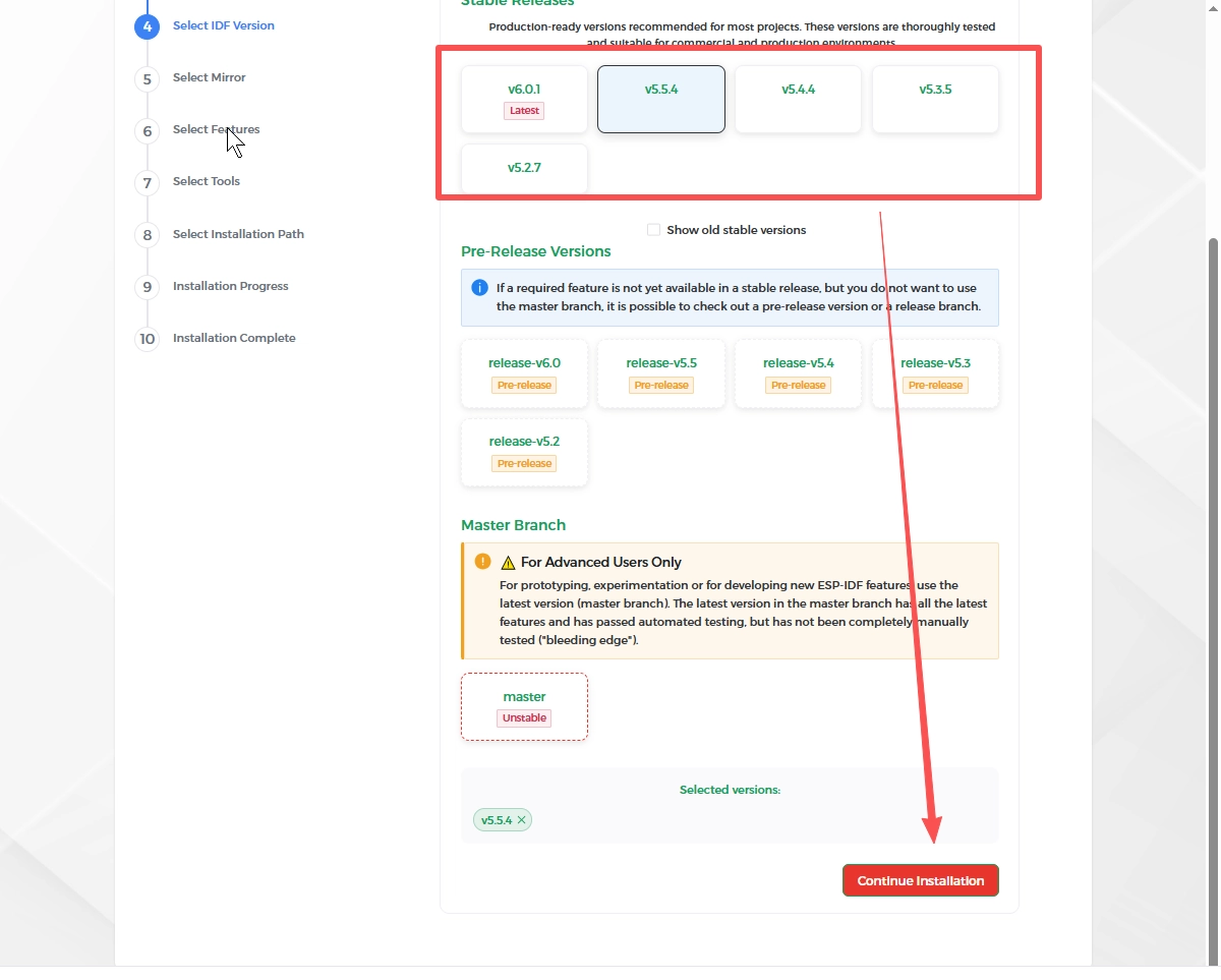
Select the ESP-IDF version (please choose the version required by your course)
Here, I choose ESP-IDF version 5.5.4.
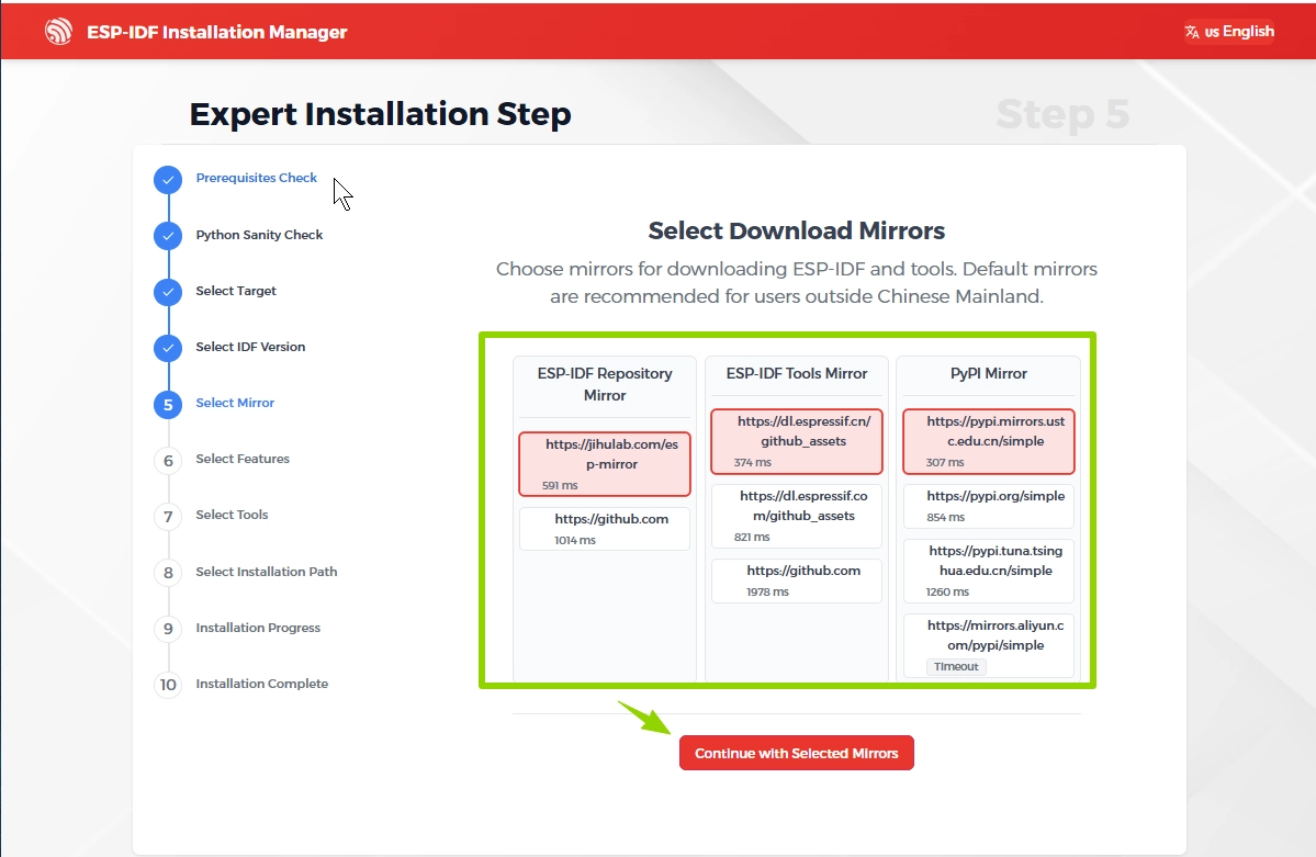
Select Download Mirrors
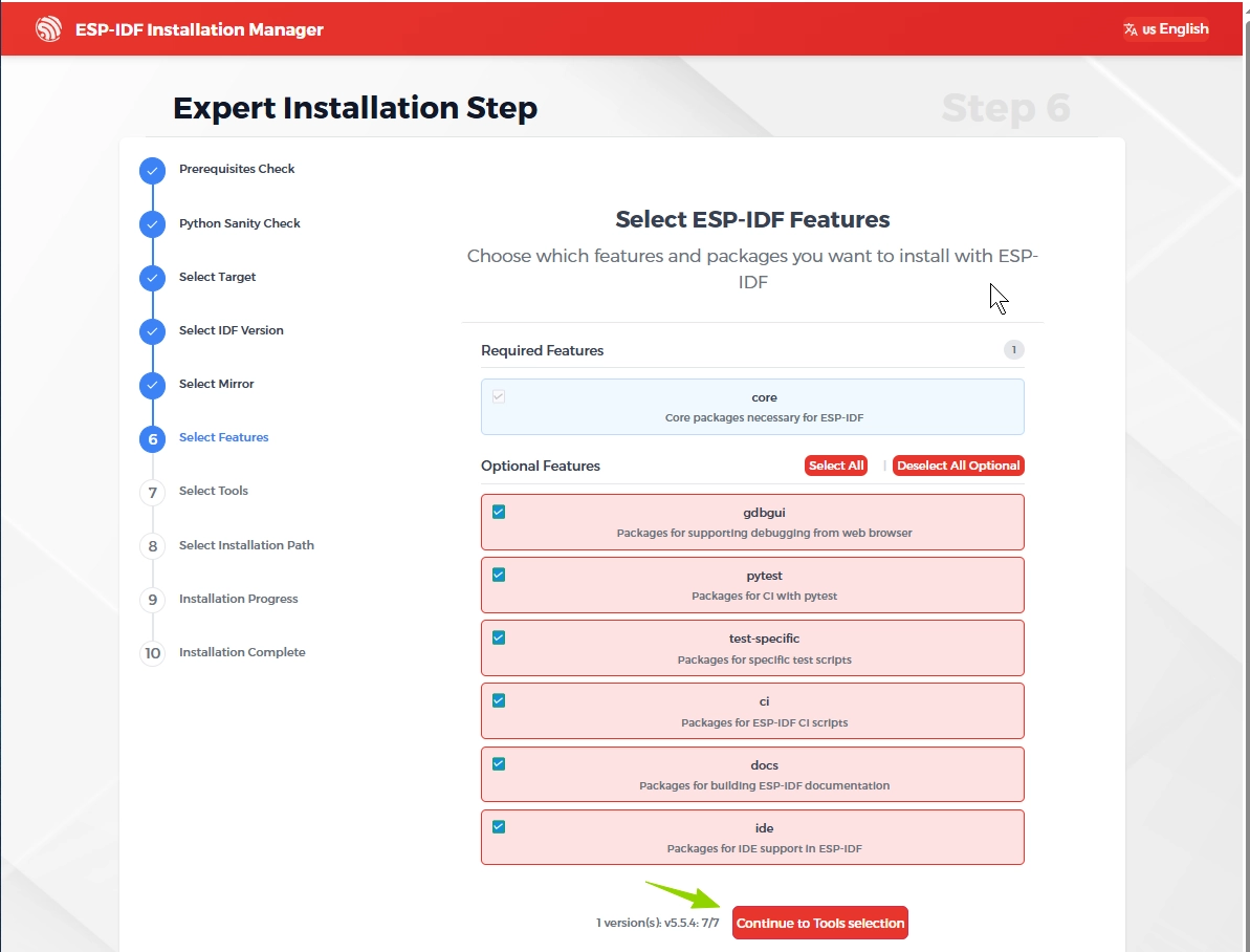
Select ESP-IDF Features
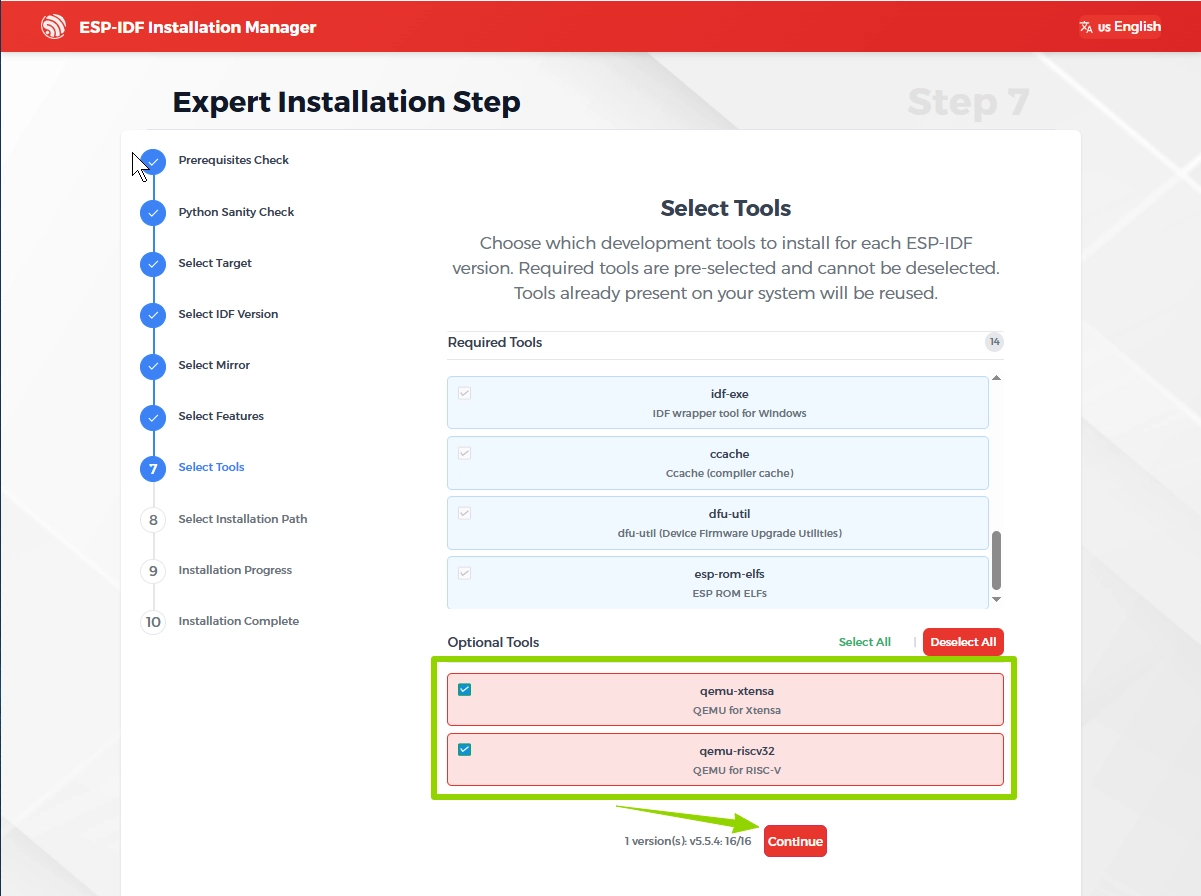
Select Tools
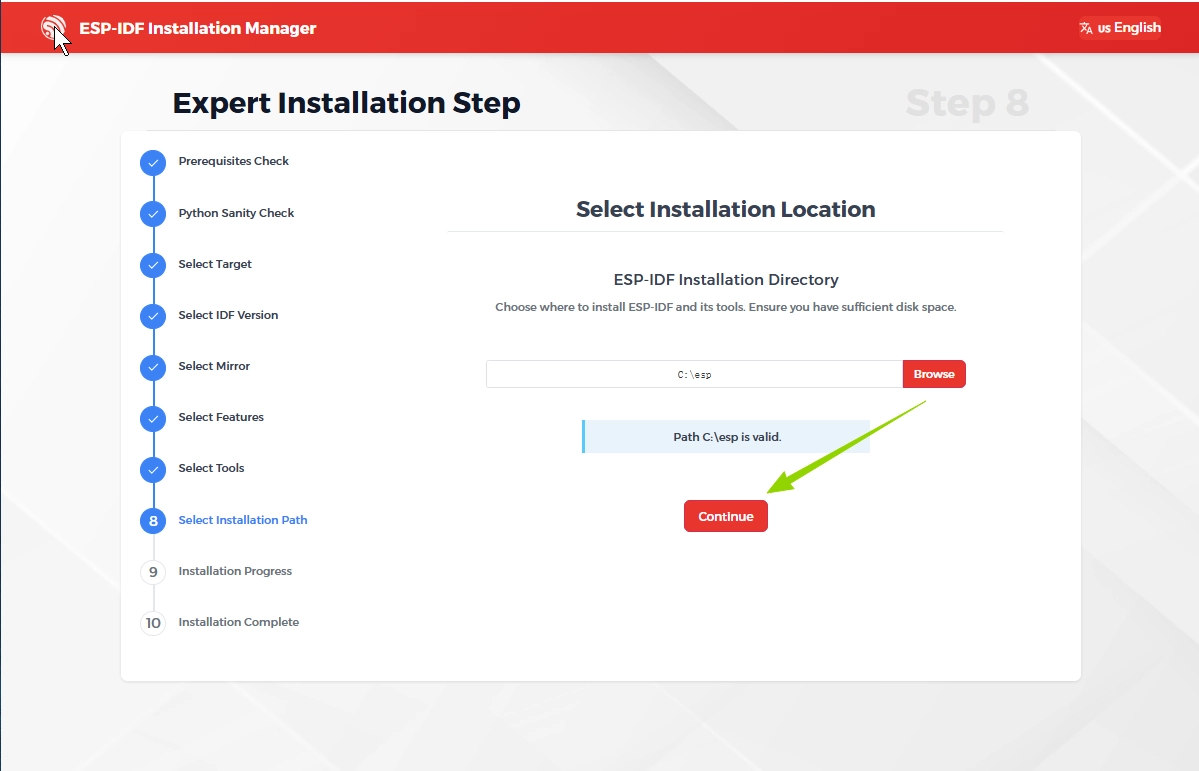
Select Installation Location
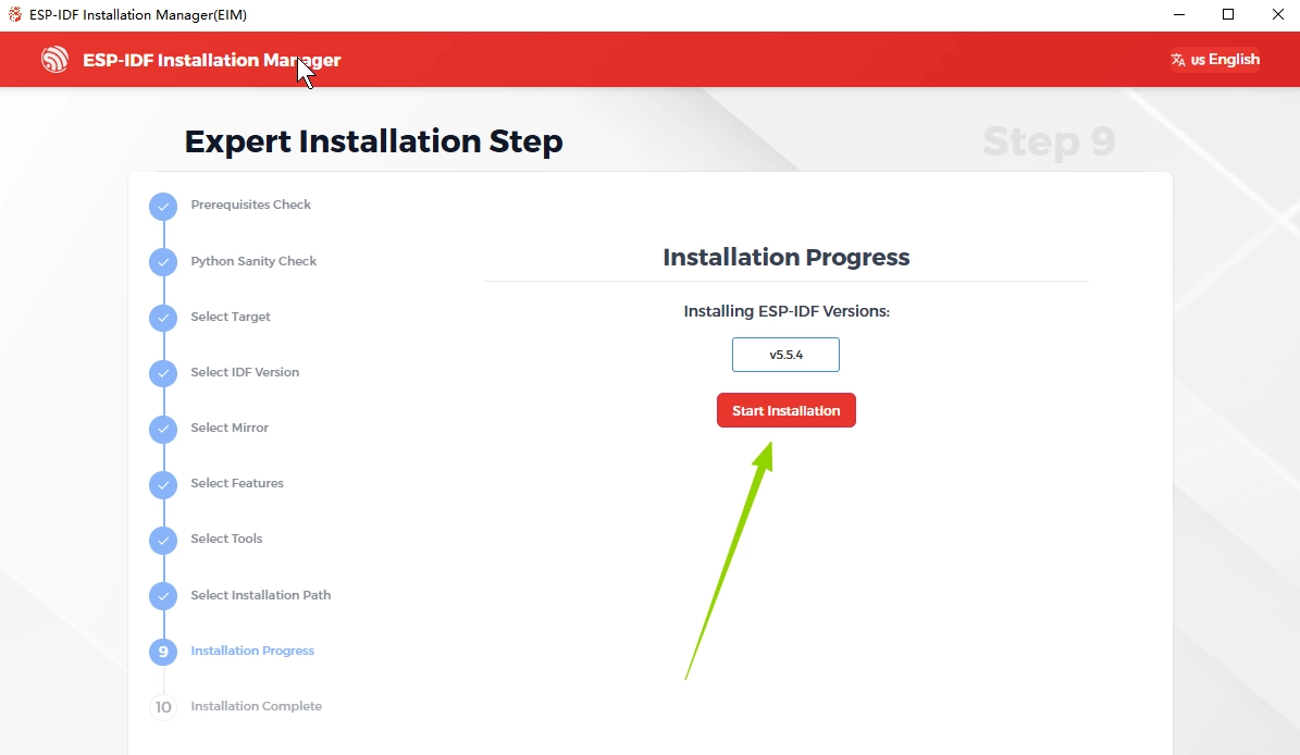
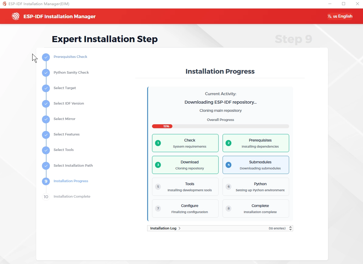
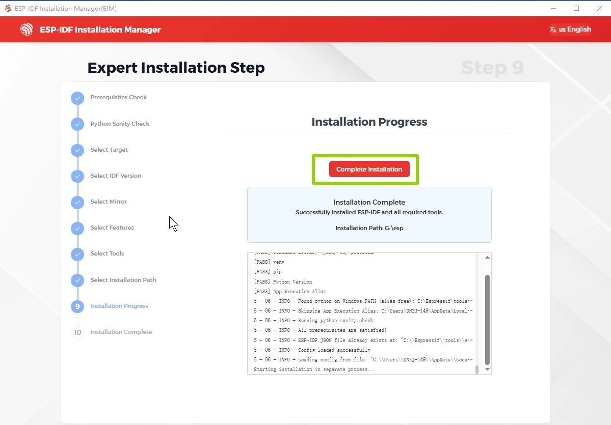
Installation progress
5. Run the program
In this case, we'll run a hello_world demo on the CrowPanel Advance HMI ESP32 AI Display to check that the installation is correct.
Before uploading the code, please complete the following preparation steps. You can follow this same procedure for every lesson to ensure that the code compiles successfully and runs as expected.
- Connect the CrowPanel Advance HMI ESP32 AI Display to the computer with a USB cable.
- After connecting your device, proceed with the operations marked as 1-10 in the figure next.
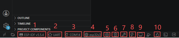
1.ESP-IDF v5.5.4:
This option is used to display the current version of ESP-IDF being used by the project. ESP-IDF is a software development framework provided by Espressif, and different versions may have different supported functions and APIs. Clicking on this option allows you to view or switch to the current ESP-IDF environment, ensuring that the project is compatible with the corresponding version of the SDK. (Here, we are using the aforementioned 5.5.4 version of the ESP-IDF development framework that was just downloaded.)
2.UART:
This option is used to display the communication method currently adopted by the development board. For most ESP32 projects, the UART serial port is used for both program downloading and running log output as well as for viewing debugging information. During the development process, communication with the development board is usually achieved through USB-to-serial conversion.
3.COM14:
This option is used to display the serial port number corresponding to the currently connected development board. When the computer is connected to multiple serial port devices, you can select the correct serial port here to ensure that the compiled firmware can be downloaded to the target development board, and at the same time, the serial port monitor can also receive log information normally.
4.esp32s3:
This option is used to specify the target chip model of the current project. ESP-IDF will automatically select the corresponding compilation configuration, drivers and startup files based on the selected chip. If the development board model changes, for example, from ESP32-S3 to ESP32-C3, then you need to re-select the corresponding target chip here.
5.SDK Configuration:
This button is used to open the menuconfig configuration interface of ESP-IDF. Here, system parameters can be configured, such as Wi-Fi, Bluetooth, Flash partition, FreeRTOS, log level, PSRAM, network protocol stack, etc. Menuconfig is one of the most important engineering configuration tools in ESP-IDF.
Here, the operation we need to carry out is:
-
The
delay()function, millisecond timing, and task scheduling in Arduino all use 1ms as the minimum time unit. Only when the FreeRTOS tick rate is 1000Hz, and the system's single clock heartbeat is exactly 1ms, can it precisely match the millisecond-level timing logic of Arduino; if it uses 100Hz (10ms per tick), the time functions will have accuracy errors and directly trigger compilation verification errors.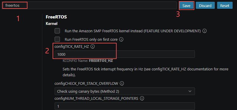
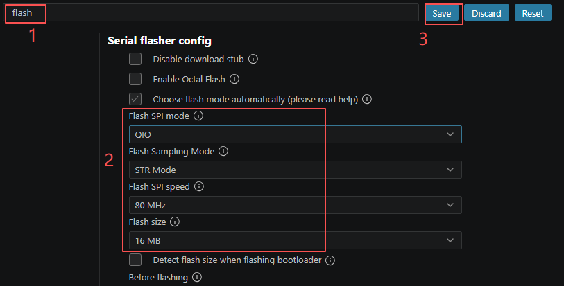
-
On the "Serial Flasher Config" page of ESP-IDF, configure the correct Flash parameters according to the hardware specifications of the used ESP32 development board. First, enter "flash" in the search box to quickly locate the relevant configuration items. Then, set the parameters such as Flash SPI Mode (QIO), Flash Sampling Mode (STR Mode), Flash SPI Speed (80 MHz), and Flash Size (16 MB) based on the actual Flash configuration of the development board. Finally, click "Save" to save the configuration. After completing these settings, ESP-IDF will use the correct Flash configuration during compilation and burning, ensuring that the firmware can be downloaded, started, and run normally.
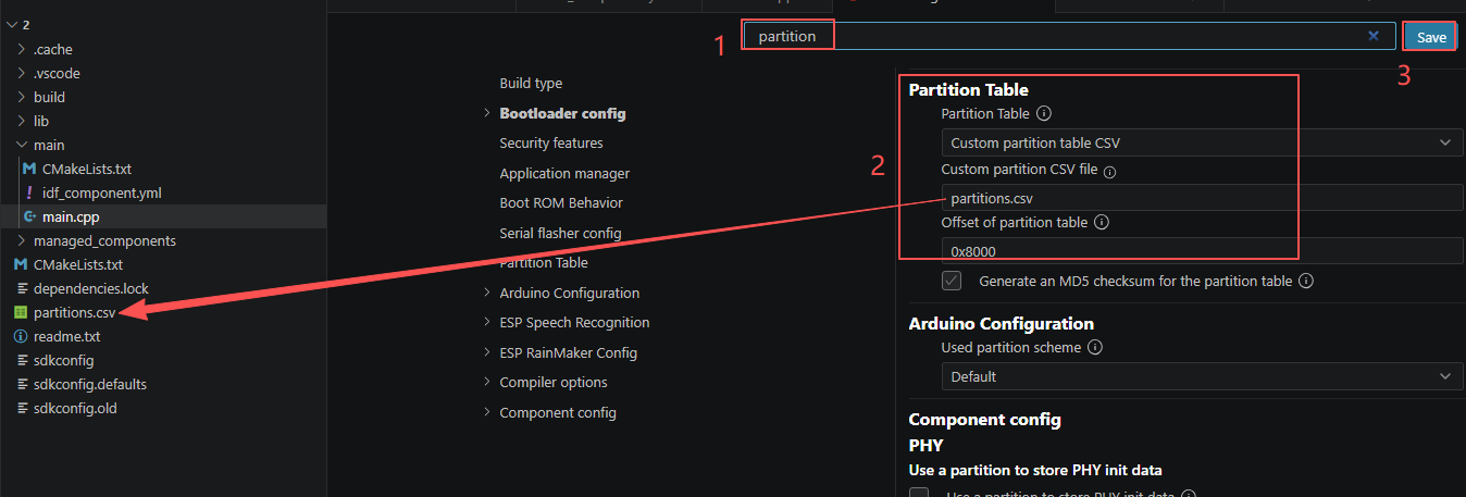
- This is the partition table setting page of the ESP-IDF graphical configuration interface. You can choose to enable a custom CSV partition table and specify the local partitions.csv file path, as well as configure the storage offset address of the partition table in the Flash.
6.Full Clean:
This button is used to completely clear the compilation cache and intermediate files of the project, which is equivalent to deleting the "build" folder. When the project configuration undergoes significant changes, strange compilation errors occur, or library files are updated, it is usually recommended to perform a Full Clean and then recompile the project.
7.Build Project:
This button is used to compile the current project. After being clicked, ESP-IDF will compile and link the source code, and generate the final firmware file (bin) for burning onto the development board. This process does not download the program to the development board; it only checks the code and generates the firmware.
8.Flash Device:
This button enables the one-click completion of the compilation and flashing operations. The system will first perform the project compilation, and once the compilation is successful, it will automatically download the generated firmware to the development board. For daily development, this is one of the most frequently used functions.
9.Monitor:
This button is used to open the serial port monitor window, allowing you to view the log information, debugging output and error prompts during the operation of the ESP32 in real time. The information output through functions such as ESP_LOGI() and printf() during the development process will be displayed in this window, making it an important tool for troubleshooting.
10.Build + Flash + Monitor:
This button is used to directly burn the already compiled firmware onto the development board without re-executing the compilation process. If the code has not changed and you only need to re-download the program, using Flash can save a significant amount of time.