Lesson02_CrowPanel_Display_LVGL: Basic Display on a 480 x 480 Round Screen
1. Course Introduction
This lesson uses ESPHome 2026.7.4 and ESPHome Device Builder 1.9.2 to configure the CrowPanel 2.1inch-HMI ESP32 Rotary Display. At startup, the ESP32-S3 enables panel power through the PCF8574 I/O expander, performs the required ST7701S reset sequence, and brings up the 480 x 480 RGB panel. SPI carries the controller commands while the RGB data bus carries the pixel stream. LVGL then displays Hello World! in the center.
Learners will add the supplied YAML to ESPHome, keep their own API key and Wi-Fi settings, validate and flash the project, and verify the display and startup log. This lesson establishes the panel, PSRAM, and LVGL rendering chain required by all later lessons.
2. Learning Objectives
- Be able to explain the startup sequence from PCF8574 panel power and reset, through ST7701S initialization, to RGB output and LVGL rendering.
- Be able to import, validate, and install the YAML configuration in ESPHome Device Builder 1.9.2.
- Be able to identify the ST7701S SPI control pins, RGB data pins, timing values, color order, and pixel-clock settings.
- Be able to determine whether the basic display experiment is successful based on the backlight, the
Hello World!page, and the serial logs.
3. Preparation
- One CrowPanel 2.1inch-HMI ESP32 Rotary Display.
- One USB data cable compatible with the rotary screen's data transfer.
- ESPHome Device Builder 1.9.2.
- ESPHome 2026.7.4.
- Available 2.4 GHz Wi-Fi.
Code download link: Elecrow Official Lesson_Code
4. Software Operation Steps
Open ESPHome Device Builder 1.9.2 and confirm that its ESPHome Core version is displayed as 2026.7.4. If the versions do not match, perform the upgrade or switch the environment first to avoid component syntax differences. 
Create a new project, place rotary-screen-21-display.yaml into the ESPHome configuration directory, and open the corresponding configuration in the device list. However, device names within the same network must not be duplicated.
A. Click Create device to create a new project.


B. Select the esp32s3 main controller.

C. Name the project. Complete the creation task.

Copy the official code into the project (the code is provided above).
However, make sure the project name in this code matches the name of the project you just created.

Modify the Wi-Fi.

Click the three dots in the upper-right corner, then click Secrets.
You can enter your own Wi-Fi name and password. (Make sure this Wi-Fi is on the same local network as your Home Assistant system.)


Click Install, select the USB installation method suitable for the current environment, choose the serial port corresponding to the CrowPanel 2.1inch-HMI ESP32 Rotary Display, and complete compilation and flashing. After flashing finishes, open the log window and confirm that the I2C scan, display initialization, Wi-Fi connection, and LVGL startup complete without repeated resets.


Wait for compilation.

After compilation completes, click Flash to upload.

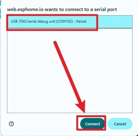
Select the connected serial port.

Click to connect to the corresponding serial port (confirm that the hardware is already connected).
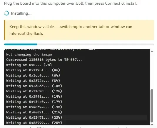
Wait for the download to complete.
5. Hardware Operation Steps
With the device powered off, check that the screen, rotary encoder housing, and USB connector show no obvious damage, then use a USB cable that supports data transfer to connect the CrowPanel 2.1inch-HMI ESP32 Rotary Display to the computer.

Wait for the LVGL page to be built, then look directly at the center of the round screen. The screen should display a white background and black Hello World!, with the text fully visible, centered, and without obvious misalignment or display corruption.

6. Key Code Explanation
6.1 ESP32-S3, PSRAM, and Boot Order
esphome:
  name: rotary-screen-21-display
  friendly_name: Rotary_Screen_2.1_Display
  platformio_options:
    build_flags: "-DBOARD_HAS_PSRAM"
    board_build.esp-idf.memory_type: qio_opi
    board_build.flash_mode: dio
  on_boot:
    priority: 800
    then:
      - output.turn_on: lcd_power
      - output.turn_on: display_reset
      - delay: 100ms
      - output.turn_off: display_reset
      - delay: 100ms

esp32:
  board: esp32-s3-devkitc-1
  framework:
    type: esp-idf
    sdkconfig_options:
      CONFIG_ESP32S3_DEFAULT_CPU_FREQ_240: y
      CONFIG_ESP32S3_DATA_CACHE_64KB: y
      CONFIG_SPIRAM_FETCH_INSTRUCTIONS: y
      CONFIG_SPIRAM_RODATA: y

psram:
  mode: octal
  speed: 80MHz
The 2.1-inch panel uses an ESP32-S3R8 with 8 MB PSRAM and 16 MB Flash. The build flags select the QIO/OPI memory arrangement and DIO Flash mode, while the ESP-IDF options allow instructions and read-only data to use PSRAM. At priority 800, panel power is enabled before reset is asserted and released. The two 100 ms delays satisfy the panel power-up and reset timing.
6.2 I2C and the PCF8574 I/O Expander
i2c:
  sda: GPIO38
  scl: GPIO39
  id: bus_a
  scan: true

pcf8574:
  - id: pcf
    address: 0x21

output:
  - platform: gpio
    id: lcd_power
    pin:
      pcf8574: pcf
      number: 3
      mode:
        output: true
      inverted: false
  - platform: gpio
    id: display_reset
    pin:
      pcf8574: pcf
      number: 4
      mode:
        output: true
      inverted: true
GPIO38 and GPIO39 form the board I2C bus. The PCF8574 at address 0x21 expands this bus into control lines used by the panel and touch hardware. P3 controls LCD power and P4 controls display reset. The reset output is inverted, so the turn_on action asserts reset and turn_off releases it. If the I2C scan does not find 0x21, the display power and reset sequence cannot work.
6.3 GPIO6 PWM Backlight
output:
  - platform: ledc
    pin: 6
    id: bl_pwm
    frequency: 19531Hz

light:
  - platform: monochromatic
    name: "LCD Backlight"
    output: bl_pwm
    id: display_backlight
    default_transition_length: 0s
    restore_mode: ALWAYS_ON
GPIO6 is the backlight PWM pin. A 19,531 Hz LEDC signal is above the visible flicker range, and the monochromatic light component exposes the same output to ESPHome and Home Assistant. ALWAYS_ON turns the backlight on after boot; later lessons write a 0.0-1.0 duty level to bl_pwm for dimming.
6.4 ST7701S Control and RGB Data Buses
spi:
  clk_pin: 2
  mosi_pin: 1

display:
  - platform: st7701s
    id: my_display
    update_interval: 50ms
    spi_mode: MODE3
    color_order: RGB
    invert_colors: false
    dimensions:
      width: 480
      height: 480
    cs_pin: 16
    de_pin: 40
    hsync_pin: 15
    vsync_pin: 7
    pclk_pin: 41
    data_pins:
      red: [46, 3, 8, 18, 17]
      green: [14, 13, 12, 11, 10, 9]
      blue: [5, 45, 48, 47, 21]
    hsync_front_porch: 20
    hsync_pulse_width: 10
    hsync_back_porch: 10
    vsync_front_porch: 8
    vsync_pulse_width: 10
    vsync_back_porch: 10
    pclk_frequency: 18MHz
    pclk_inverted: true
This panel is not driven like a small SPI-only LCD. GPIO2, GPIO1, and GPIO16 send ST7701S setup commands, while the DE, synchronization, pixel-clock, and RGB data pins continuously carry the 480 x 480 pixel stream. The 18 MHz inverted pixel clock and porch values determine line and frame timing. Keep the complete manufacturer initialization sequence from the lesson YAML unchanged; it configures gamma, power, scan direction, pixel format, sleep exit, and display-on commands.
6.5 LVGL Hello World Label
lvgl:
  displays:
    - my_display
  widgets:
    - label:
        align: CENTER
        id: lbl_title
        text_font: montserrat_28
        text: "Hello World!"
LVGL uses my_display as its rendering target and creates one centered label. If the panel is lit but the label does not appear, check LVGL startup and font availability. If neither the background nor text appears, return to the PCF8574, reset, ST7701S, and RGB timing configuration first.
7. Experimental Observations
After initialization, the 480 x 480 round screen should show Hello World! in the center. The image must remain stable without color corruption, horizontal tearing, repeated resets, or obvious clipping at the circular edge. A stable result verifies the ESP32-S3, PSRAM, I2C expander, panel reset, ST7701S command bus, RGB pixel bus, and basic LVGL rendering chain.