ThinkNode M9 MeshCore Communication Terminal with Full Keyboard
Document version: 2026-08-13
Applicable device: Elecrow ThinkNode M9 V1.0
Applicable software: MeshCore Ripple v12.0 as shown in the device photos; menus may change with firmware updates.
Table of Contents
- 1. Product Introduction
- 1.1 Product Overview
- 1.2 Safety Information and Unboxing
- 1.3 Hardware Architecture and Specifications
- 1.4 Official and Reference Resources
- 2. Product Pinout
- 2.1 Main ESP32-S3 GPIO Summary
- 2.2 LR1110 LoRa
- 2.3 LCD
- 2.4 microSD/TF Card
- 2.5 GNSS
- 2.6 RTC and Sensors
- 2.7 Keyboard Subsystem
- 2.8 Other Hardware Signals
- 3. Software Operation
- 3.1 Power-On, Creating a New Network, and Basic Controls
- 3.2 Home and Extra Pages
- 3.3 Network and Radio Settings
- 3.4 Channel Communication
- 3.5 Discover, Contacts, and Private Chats
- 3.6 GPS and Maps
- 3.7 Wi-Fi and Official Unlocking
- 3.8 Repeater, Regions, and Scope
- 3.9 Firmware, Storage, and Maintenance
- 3.10 Troubleshooting
1. Product Introduction
1.1 Product Overview
The MeshCore version of the ThinkNode M9 is a standalone MeshCore communication terminal with a display, full keyboard, and battery. The device integrates an ESP32-S3, LR1110 LoRa, GNSS, 2.4-inch LCD, dual-MCU keyboard, microSD, RTC, magnetic sensor, motion sensor, buzzer, Wi-Fi, and Bluetooth. It can handle text communication, contact management, channel chats, and location viewing without relying on a phone.
In MeshCore, the M9 operates as a Standalone/Client terminal by default. It can send and receive multihop messages through a Repeater, but ordinary handheld terminals do not automatically forward messages for other nodes.
Typical uses:
- Offline text communication in areas without cellular coverage;
- Hiking, camping, event coordination, and emergency communication;
- Public channels, private channels, and private chats with contacts;
- GNSS positioning, location sharing, and offline map viewing;
- MeshCore network inspection and Repeater path diagnostics.
1.2 Safety Information and Unboxing
1.2.1 Safety Information
- Before powering on or transmitting, install a LoRa antenna that matches the hardware frequency band.
- Frequency, BW, SF, CR, and TX Power must comply with local regulations and the target network plan.
- Do not disclose the device's private key, private channel keys, administrative password, or precise home location.
- Ensure that the battery has sufficient charge during firmware updates. Do not power off the device, disconnect cables, or remove the card.
- Use only firmware explicitly intended for the ThinkNode M9.
- The LCD, TF card, and LR1110 share the same SPI bus. When developing custom firmware, manage each CS correctly and never select multiple peripherals simultaneously.
1.2.2 Package Contents
- ThinkNode M9 unit;
- USB-C data/charging cable;
- ThinkNode M9 Starter Card;
1.3 Hardware Architecture and Specifications
1.3.1 Key Specifications
| Item | ThinkNode M9 V1.0 |
|---|---|
| Main controller | ESP32-S3-R8 |
| Keyboard controller | ESP32-S2 |
| LoRa | Semtech LR1110 |
| GNSS | ATGM336H-5NR32 / BM72A |
| Display | 2.4-inch color LCD, 320 × 240 |
| RTC | PCF8563 |
| Magnetic sensor | QMC6309 |
| Motion sensor | QMI8658B |
| Flash | ZD25Q128CSIGT |
| USB-UART | CH340K |
| Storage | microSD/TF |
| Wireless connectivity | 2.4 GHz Wi-Fi, Bluetooth, LoRa |
| Battery | 2300 mAh rechargeable lithium battery |
| Charging/data | USB-C |
1.3.2 Hardware Block Diagram
                       +-------------------+
USB-C -- CH340K ------>|                   |<------ Wi-Fi / Bluetooth
                       |   ESP32-S3-R8 U9   |
GNSS UART/PPS -------->|                   |<-- I2C --> RTC
                       |                   |<-- I2C --> QMC6309 + QMI8658B
                       +---------+---------+
                                 |
                  shared SPI: SCK/MOSI/MISO
                    +------------+------------+
                    |            |            |
                 LR1110        LCD          microSD
                 own NSS       own CS       own CS

ESP32-S2 U10 <---- SDA/SCL + WAKEUP ----> ESP32-S3 U9
      |
      +---- keyboard matrix, shortcut keys and keyboard LED
1.4 Official and Reference Resources
2. Product Pinout
2.1 Main ESP32-S3 GPIO Summary
Multiplexed pins such as MTCK/MTDO/MTDI/MTMS in the ESP32-S3 symbols correspond to GPIO39/GPIO40/GPIO41/GPIO42, respectively; SPICLK_P/SPICLK_N correspond to GPIO47/GPIO48, respectively; and XTAL_32K_P/XTAL_32K_N correspond to GPIO15/GPIO16, respectively.
| Schematic Net | ESP32-S3 GPIO | Purpose |
|---|---|---|
IO0_BOOT | GPIO0 | Main controller BOOT |
5V_TEST | GPIO1 | 5 V detection/test net |
GPS_TX | GPIO2 | Main controller receives GNSS TX |
GPS_RX | GPIO3 | Main controller transmits to GNSS RX |
1PPS_TEST | GPIO4 | GNSS 1PPS |
GPS_RST1 | GPIO5 | GNSS reset control |
SCL | GPIO6 | RTC I2C SCL, isolated through a resistor |
SDA | GPIO7 | RTC I2C SDA, isolated through a resistor |
DONE | GPIO8 | Power/charging status net |
BUZZER_EN | GPIO9 | Buzzer enable |
GPS_ON/OFF | GPIO10 | GNSS on/off control |
GPS_EN | GPIO11 | GNSS power enable |
ESP32_WAKEUP | GPIO12 | Keyboard coprocessor wakes the main controller |
BAT_ADC | GPIO13 | Battery-voltage ADC |
LCD_RESET | GPIO14 | LCD reset |
LCD_RS | GPIO15 | LCD RS/DC |
LCD_CS | GPIO16 | LCD chip select |
BL_EN | GPIO17 | LCD backlight enable |
VDD_PERIPH_EN | GPIO18 | Peripheral power enable |
LCD_TE | GPIO19 | LCD tearing-effect signal |
ESP32-2_SDA | GPIO20 | Data line between the main controller and keyboard coprocessor |
ESP32-2_SCL | GPIO21 | Clock line between the main controller and keyboard coprocessor |
ESP32_MISO | GPIO38 | Shared SPI MISO |
LR_NSS | GPIO39 | LR1110 chip select/NSS |
ESP32_SCK | GPIO40 | Shared SPI SCK |
LR_BUSY | GPIO41 | LR1110 BUSY |
INTERRUPT | GPIO42 | LR1110 DIO9/interrupt |
LR_NRESET | GPIO45 | LR1110 reset |
KEY_LED | GPIO46 | Keyboard light control net |
ESP32_MOSI | GPIO47 | Shared SPI MOSI |
SD_CS | GPIO48 | microSD chip select |
2.2 LR1110 LoRa
| LR1110 Signal | ESP32-S3 GPIO | Description |
|---|---|---|
LR_NSS / DIO1 | GPIO39 | SPI chip select; the LR1110 SPI signals are labeled DIO1-DIO4 in the schematic |
ESP32_SCK / DIO2 | GPIO40 | SPI clock |
ESP32_MOSI / DIO3 | GPIO47 | SPI controller out/peripheral in |
ESP32_MISO / DIO4 | GPIO38 | SPI controller in/peripheral out |
LR_BUSY / DIO0 | GPIO41 | Busy status |
INTERRUPT / DIO9 | GPIO42 | Interrupt |
LR_NRESET / NRESET | GPIO45 | Reset |
| DIO7, DIO8 | Not connected to main controller GPIO | Nets reserved in the schematic |
2.3 LCD
| LCD Signal | ESP32-S3 GPIO | FPC J6 |
|---|---|---|
LCD_RESET | GPIO14 | 1 |
LCD_RS | GPIO15 | 2 |
ESP32_SCK | GPIO40 | 3 |
LCD_CS | GPIO16 | 5 |
DISPLAY_VDD | Power | 6, 7 |
LCD_TE | GPIO19 | 8 |
ESP32_MOSI | GPIO47 | 9 |
| GND | - | 10, 13, 14 |
LCD_A / LCD_K | Backlight circuit | 11, 12 |
BL_EN | GPIO17 | Backlight MOS control; not used directly as a logic signal on the FPC |
2.4 microSD/TF Card
| TF Signal | ESP32-S3 GPIO | Description |
|---|---|---|
SD_CS / CD-DAT3 | GPIO48 | Chip select |
ESP32_SCK / CLK | GPIO40 | Shared SPI clock |
ESP32_MOSI / CMD | GPIO47 | Shared SPI MOSI |
ESP32_MISO / DAT0 | GPIO38 | Shared SPI MISO |
SD_3V3 | - | Card power |
SPI usage rule: Before initializing or accessing a peripheral, ensure that only the target peripheral's CS is low among LR1110 NSS, LCD CS, and SD CS, and keep all others high.
2.5 GNSS
| GNSS Signal | ESP32-S3 GPIO | Description |
|---|---|---|
GPS_TX | GPIO2 | GNSS TX → ESP32 RX |
GPS_RX | GPIO3 | ESP32 TX → GNSS RX |
1PPS_TEST | GPIO4 | Pulse per second |
GPS_RST1 | GPIO5 | Reset control |
GPS_ON/OFF | GPIO10 | Module ON/OFF |
GPS_EN | GPIO11 | Power enable |
GPS_BAT | Backup power | Preserves ephemeris/RTC state |
2.6 RTC and Sensors
| Module | Bus/Signal | ESP32-S3 GPIO | Notes |
|---|---|---|---|
| PCF8563 RTC | SCL | GPIO6 | Dedicated RTC I2C net |
| PCF8563 RTC | SDA | GPIO7 | Dedicated RTC I2C net |
| QMC6309 | 3D_SCL | GPIO6, through R44 | Shares the sensor I2C bus with the QMI8658B |
| QMC6309 | 3D_SDA | GPIO7, through R47 | Magnetometer |
| QMI8658B | 3D_SCL | GPIO6, through R44 | Motion sensor |
| QMI8658B | 3D_SDA | GPIO7, through R47 | CS connected high and SDO/SA0 grounded; operates in I2C mode |
| Peripheral power | VDD_PERIPH_EN | GPIO18 | Enables power to sensors/LCD-related peripherals |
2.7 Keyboard Subsystem (ESP32-S2 U10)
The keyboard matrix is scanned by a separate ESP32-S2, which communicates with the main controller through ESP32-2_SDA/SCL and uses GPIO12 to wake the main controller.
| Function | ESP32-S2 GPIO |
|---|---|
| ROW1 / ROW2 / ROW3 / ROW4 / ROW5 | GPIO40 / GPIO42 / GPIO45 / GPIO9 / GPIO19 |
| COL1-COL5 | GPIO36 / GPIO37 / GPIO20 / GPIO21 / GPIO11 |
| COL6-COL10 | GPIO1 / GPIO2 / GPIO3 / GPIO4 / GPIO5 |
| KEY_INT | GPIO12 |
| Main controller communication SDA / SCL | GPIO7 / GPIO6 |
| Wake line | GPIO8 |
| Keyboard light | GPIO41 |
| Coprocessor BOOT | GPIO0 |
Dedicated keys are also connected individually to GPIO18, GPIO10, GPIO39, GPIO38, GPIO33, and GPIO34. During development, refer to the keyboard firmware and the switch identifiers in the schematic; do not assume that key values correspond to main controller GPIO numbers.
2.8 Other Hardware Signals
| Function | GPIO/Device | Description |
|---|---|---|
| Buzzer | GPIO9 BUZZER_EN | Controlled through a driver transistor |
| Battery monitoring | GPIO13 BAT_ADC | Routed to the ADC through a voltage divider and filter |
| USB-UART | CH340K U3 | Used for serial communication/maintenance; USB D+/D- are also connected to the USB interface net |
| RTC backup | PCF8563 + RTC_3V3 | Powered by the backup power net |
| Charging | LGS4056HDA-4.35 U6 | The schematic specifies the charging-current formula as I=1000/R |
3. Software Operation
3.1 Power-On, Creating a New Network, and Basic Controls
3.1.1 Power-On
After installing the antenna and charging the device, power it on. The device first displays Elecrow, followed by MeshCore Ripple.
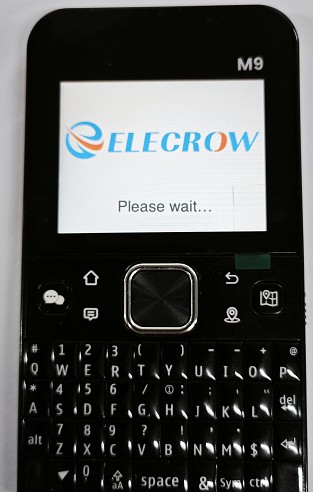
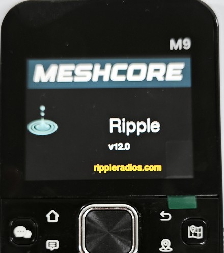
On first startup, an online user guide QR code is displayed. Scan the code to read the guide, or select OK to continue.

3.1.2 Built-In Control Tutorial
HELP : Selection means: Use the Up/Down directional buttons to move the selection bar to SELECT THIS, then press the center button.

In the menu tutorial, first press the menu button to open the menu in the upper-right corner, then move to SELECT THIS and press the center button to confirm.

Press and hold the center button for approximately 1 second to turn off the screen. Press it once to turn the screen back on. Continue pressing the center button to advance to the next help page.

3.1.3 Basic Controls
| Button | Function |
|---|---|
| D-pad Up/Down/Left/Right | Move focus, scroll through lists, or pan the map |
| D-pad center button | Confirm/open; on some pages, press and hold to turn off the screen |
| Home | Return to the Home page |
| Back | Return to the previous page |
| Menu button | Open the menu in the upper-right corner |
| Chat shortcut | Open the chat/message page |
| Map shortcut | Open the map |
| Location button | Positioning/location functions |
| QWERTY keyboard | Enter names and messages |
3.1.4 Creating a New MeshCore Network
- Under
New Network → Select Type, selectMeshCore.

- Under
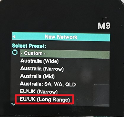
Select Preset, select a preset that complies with local regulations and the community network plan. The example shown in the photo usesEU/UK (Long Range), which is suitable only in regions where this configuration is permitted; do not duplicate it in other regions.
- Enter a
Network Nameand confirm. The name is used to identify the network locally and does not replace the radio parameters or channel key.

- After saving, the Home page appears. For two devices to communicate, their Frequency, BW, SF, CR, channel key, and any required Scope settings must be compatible.
3.2 Home and Extra Pages
3.2.1 Home Page Information
| Screen Area/Item | Description |
|---|---|
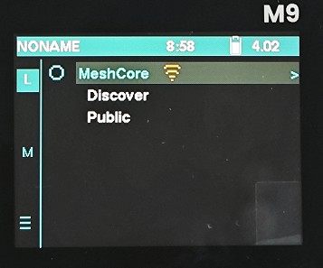
| Name at the top | Current device/network display name; NONAME is shown in the image |
| Time | Current device time; an incorrect time can affect the evaluation of discovery records |
| Battery icon and voltage | Battery status and measured voltage |
L / M | Left-side page/mode labels; their exact meanings vary by firmware version |
| Circular status icon | LoRa/node status indicator |
MeshCore | Current network configuration; the Wi-Fi icon on the right indicates the relevant status and does not necessarily mean that the device is connected to a network |
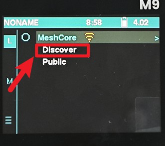
Discover | Discover nodes, send an ID, and scan for directly reachable nodes |
Public | Default public channel |
Channel #1... | Enabled private channels |
| Lower-left menu | Open the function menu/additional items |
3.2.2 Extra Page
From the Home page, open preset information/Extra. The photos show three sections of the same scrollable list.

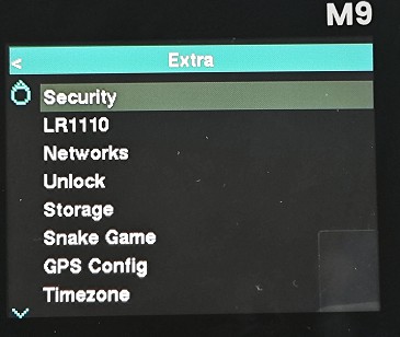

| Item | Function |
|---|---|
| GPS Info | View satellites, Fix, latitude/longitude, accuracy, and time |
| Sound | Message/key sound mode |
| Vib/LED | Vibration and LED notification mode |
| Timestamps | Toggle message timestamps |
| Brightness | Screen brightness/day and night mode |
| Display | Display and sleep settings |
| Wi-Fi | Wi-Fi on/off, scanning, and connection; official unlocking may be required |
| Security | Security, keys, and related permission settings |
| LR1110 | LoRa chip/RF-related information or settings |
| Networks | Network configuration list and Profile Details |
| Unlock | Official license-unlocking entry point |
| Storage | microSD, storage space, and file functions |
| Snake Game | Built-in mini-game |
| GPS Config | GNSS operating mode and configuration |
| Timezone | Time zone settings |
| Waypoints | Waypoint management |
| Canned | Preset/quick messages |
| Help | Built-in operating instructions |
3.3 Network and Radio Settings
Path: Extra → Networks → Select Profile → Profile Details.

| Item | Meaning | Interoperability Requirements |
|---|---|---|
| Name | Profile name | Display name only; does not determine interoperability |
| Frequency | Center frequency, MHz | Must match and comply with regulations |
| SF | Spreading factor | Must match; higher values are generally slower but provide better weak-signal performance |
| CR | Coding rate | Must match; greater redundancy increases airtime |
| BW | Bandwidth, kHz | Must match; wider bandwidth generally provides higher speeds |
The example shown in the photo is 869. 525 MHz / SF11 / CR5 / BW250. It is only an EU/UK Long Range example, not a globally applicable setting. Prefer a complete Preset provided by the manufacturer or local community instead of changing only the Frequency.
For a read-only check in Terminal, use:
The returned values are typically ordered as follows:
Do not use set radio or set TX Power to the maximum unless you understand the hardware frequency band, applicable regulations, and network parameters.
3.4 Channel Communication
3.4.1 Public Channel
Public uses a publicly shared key. It is suitable for testing, announcements, and public communication, but not for passwords, private locations, or other sensitive information.
3.4.1.1 Sending
- Select
Publicon the Home screen. - After entering
MeshCore.Public, type a message in the input field at the bottom. - Press the Send/Confirm key, then wait for the message to appear in the list and for wireless retries to complete.
3.4.1.2 Receiving and Interpreting Messages
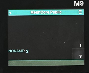
Received messages are displayed as "node name: content." In the photo, NONAME: 2 means that the node named NONAME sent the content 2.

- Channel messages typically use Flood; do not rapidly resend the same content.
- A local message appearing on the Public page does not necessarily mean that all remote nodes have received it.
- If messages are not received, check the four Radio parameters, channel key, time, antenna, and Scope.
3.4.2 Private Channels
The confidentiality of a private channel comes from its channel key, not its channel name. All members must use the same channel name/slot configuration, an identical key, compatible Radio parameters, and the same Scope.
3.4.2.1 Creating and Enabling a Channel
- From the Home screen, open
MeshCoresettings. - Scroll down to
Channel #1and open it.

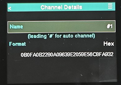
- Set the name under
Channel Details. A name beginning with#can be used as an automatic channel name. The photo shows the Hex format and displays the channel key.
- Use the menu/preset information button in the upper-right corner of the page to enable and save the channel.
- Configure the same channel name and key on the other device. Transfer the key through a trusted end-to-end channel; never post it to Public.
3.4.2.2 Sending and Receiving Messages
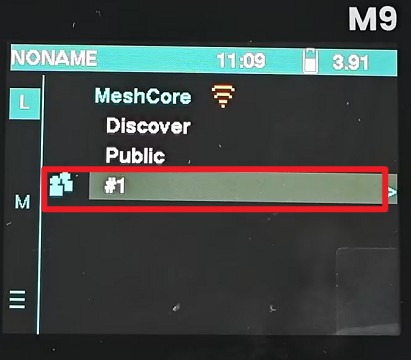
After the channel is saved and enabled, a channel entry appears on the Home screen (#1 in this example).
Open the channel, enter a message, and send it. Received channel messages are also displayed as "node name: content."

If the key is compromised or a member leaves, create a new channel with a new random key and migrate the members to it. Changing only the name does not prevent anyone with the old key from receiving messages.
3.5 Discover, Contacts, and Private Chats
3.5.1 Discovering Each Other
- Configure both M9 devices with the same Radio Preset, install their antennas, place them close together, and turn them on.
- From the Home screen, open
Discover.
- On device A, open the menu in the upper-right corner and select
Send ID Localto send the device identity only within direct communication range.

- On device B, select
Scan Local...to scan for directly connected zero-hop nodes.

- Reverse the process so that both devices can see each other. Use
Send ID Broadcastonly when propagation through a Repeater is required; do not broadcast frequently.
3.5.2 Adding a Contact and Starting a Private Chat
- Open the target node in the Discover results.
- Verify its name, public key/identity information, and last-heard time.
- Select
Add to ContactsorSave Contact. - Open the contact conversation from Contacts or Chats, enter text, and send it.
- The first message may use Flood for route discovery; subsequent messages typically use a learned directed route.
- If delivery repeatedly fails, check whether the other device is online and verify the Radio, Scope, and Repeater settings. Use Trace/Optimise to rebuild the route if necessary.
Heard only indicates that a broadcast or packet from the target was received. It does not mean that the other party received or read a private message.
3.6 GPS and Maps
3.6.1 Acquiring a GPS Fix
- Go to an open outdoor area away from tall buildings, metal structures, and obstructions inside vehicles.
- Open
Extra → GPS Infoor use the location shortcut, and confirm that GPS is enabled. - Keep the device stationary and wait for the status to change from Searching to
Fix/Valid. - Check the satellite count, latitude, longitude, UTC time, and accuracy.
- Use the coordinates for navigation or location sharing only after obtaining a new valid Fix. Without a Fix, the device may display the last cached location.
GPS is not required for LoRa chat, but it is used for automatic time synchronization, current location, distance, direction, and location sharing.

3.6.2 Viewing the Map
- Prepare a reliable FAT32 microSD card and load offline map data onto it as required by the current firmware.
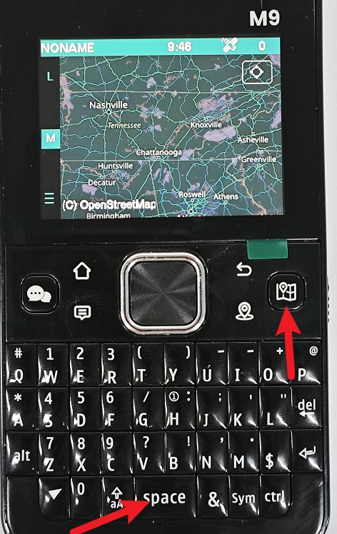
- Press the map shortcut or Space key to open Map.
- Press the location/position key to center the map on the current GPS Fix.
- Use the D-pad to pan and the keys indicated on the page to zoom.
- Open a location card received from a contact or channel and select
Show on Mapto view the other party's location.
You can still browse existing offline maps without a GPS Fix, but "my location," distance, and direction will be unavailable or inaccurate. If the map is blank, check whether the microSD card is recognized, as well as the map directory/tile format, zoom level, and coverage area.
3.6.3 Location Privacy
none: Advert does not include a location;share: Shares the current GPS Fix;prefs: Shares a saved static location.
Assess personal safety and privacy risks before sharing your precise location in Public or in a broadcast identity.
3.7 Wi-Fi and Official Unlocking
Wi-Fi is used for online time synchronization, Internet Link, CoreBrowser, OTA, and certain Companion features. It is not required for basic LoRa communication.
The M9/firmware may lock Wi-Fi or network connectivity features. You must contact the manufacturer or seller to obtain the required device license and unlock these features: Unlock URL: register.rippleradios.com.
- Open
Extra → UnlockorSettings → About/Activate/License. - Record the order number, device serial number/public key, firmware version, and error message.
- Follow the official Elecrow/MeshCore support process to obtain a device-specific unlock code or license file.
- Import the license under
Unlock/Activate/Import License, then restart the device. - Open
Extra → Wi-Fi, enable Wi-Fi, then scan for and select a 2.4 GHz SSID. - Enter the password, confirm that
Connectedand an IP address appear, then test online time synchronization or Internet Link.
Do not use third-party cracking patches, shared online licenses, or firmware not intended for the M9. Licenses are typically bound to a device identity and cannot be reused on another M9.
3.8 Repeater, Regions, and Scope
3.8.1 Node Roles
| Role | Function |
|---|---|
| Standalone/Client | Default M9 role for chats, contacts, and location; does not automatically forward packets |
| Repeater | Forwards matching MeshCore packets to extend coverage |
| Room Server | Provides room/BBS services and may participate in forwarding depending on its configuration |
| Sensor | Sends telemetry or alert data |
3.8.2 Regions and Scope
Regions are logical propagation areas, not 433/868/915 MHz RF regions.
Set as Home: Specifies the Region to which the local device belongs;Set Default Scope: Specifies the message Scope used when none is explicitly selected;- A larger Scope may increase the Flood range and airtime usage;
- Keep the default settings when there is no unified community plan; do not arbitrarily create an incompatible Region tree.
3.8.3 Repeater Usage Guidelines
By default, an M9 handheld terminal is not a dedicated Repeater. To extend coverage, deploy a compatible device running Repeater firmware, configure it with the same Radio parameters as the M9, and assign it a unique name, location, and strong administrative password. Use Trace, Heard, RSSI, and SNR to inspect the route.
3.9 Firmware, Storage, and Maintenance
3.9.1 microSD
A microSD card can be used for offline maps, license files, logs, and firmware updates. A reliable FAT32 card is recommended. Directory and tile formats vary by firmware version; always follow the release notes for the current M9 firmware.
3.9.2 Firmware Updates
Before updating:
- Ensure that the battery is sufficiently charged;
- Back up channel names, channel keys, and important settings;
- Confirm that the filename/release page explicitly identifies the firmware as being for the M9;
- Read the release notes and verify the SHA-256 checksum, if provided.
Firmware update URL: https://meshcore.io/flasher
3.10 Troubleshooting
3.10.1 Discover Cannot Find a Node
- Confirm that Frequency, BW, SF, and CR are identical on both devices.
- Check the antennas and hardware frequency bands.
- Place the devices close together. Run Send ID Local on device A and Scan Local on device B, then reverse the process.
- Check the device time and Scope.
- Check whether RX, RSSI, and SNR values change in the diagnostics.
3.10.2 A Node Is Visible, but Messages Are Not Received
- Public/private channels: Check the channel key, Radio, and Scope;
- Private chats: Check the contact identity, route, Repeater, and whether the other party is online;
- Do not treat a message appearing in the local device's list as proof that it was delivered to the remote device.
3.10.3 The Wi-Fi Icon Is On, but the Device Cannot Access the Internet
The icon may only indicate that Wi-Fi is enabled. Check whether the device has been officially unlocked, whether the SSID uses 2.4 GHz, the password, the Connected status, the IP address, and any router access restrictions.
3.10.4 GPS Does Not Acquire a Fix for an Extended Period
Go to an open outdoor area and remain stationary while waiting. Check GPS Config, power, and antenna status. A cold start may take several minutes. The absence of a Fix does not affect basic LoRa chat.
3.10.5 The Map Is Blank
Check the microSD card, FAT32 formatting, directory/tile format, zoom level, and map coverage area. The absence of a GPS Fix only affects positioning and should not prevent you from browsing existing offline tiles.
For initial acceptance testing, complete the following steps in order: confirm the antenna and frequency band → create the correct Preset → run Send ID Local/Scan Local on the two devices → send and receive messages in Public → send and receive messages in a private channel using the same key → test private messaging with a contact → acquire an outdoor GPS Fix → verify map positioning → connect to Wi-Fi after completing the official unlock process.
How to buy
Please visit this page to purchase thinknode-m9-meshcore.
Support
If you encounter any issues while using the service, you can contact us via the social media links in the bottom-right corner of elecrow or send an email to techsupport@elecrow.com for technical support.