Lesson03_CrowPanel_Rotary_Backlight: Adjusting Screen Brightness with the Rotary Knob
1. Course Introduction
Building on the basic display pipeline from Lesson 02, this lesson adds rotary knob input and PWM backlight control for the CrowPanel 2.1inch-HMI ESP32 Rotary Display. When the program starts, it sets the backlight to 50%, temporarily freezes the encoder events, and makes LVGL display Knob Screen Brightness and 50%. After initialization completes, each valid rotation step increases or decreases the brightness by 5%, with the value clamped to the range of 0%–100%, and the on-screen percentage updates synchronously.
Learners will complete a full verification of the chain from "knob phase signal → ESPHome encoder count → brightness state → PWM output → LVGL label." This lesson does not use touch functionality, making it easier to independently determine whether knob direction, debounce filtering, and backlight changes are working correctly.
2. Learning Objectives
- Be able to explain how the A/B phases of a rotary encoder produce direction and count changes.
- Be able to explain why
encoder_readyblocks knob events during the startup phase. - Be able to explain the conversion relationship between integer brightness of 0%–100% and PWM output of 0.0–1.0.
- Be able to determine whether the dimming chain is correct through knob feel, the on-screen percentage, and the actual backlight.
- Be able to troubleshoot common issues such as reversed direction, skipped steps, unsynchronized values, and no backlight change.
3. What You Need to Prepare
- A CrowPanel 2.1inch-HMI ESP32 Rotary Display that has completed the basic display verification from Lesson 02.
- A USB data cable that supports data transfer.
- ESPHome Device Builder 1.9.2.
- ESPHome 2026.7.4.
Code download link: Elecrow Official Lesson_Code
4. Software Operation Steps
Open ESPHome Device Builder 1.9.2 and confirm that its ESPHome Core version displays as 2026.7.4. If the versions do not match, complete the upgrade or switch the environment first to avoid component syntax differences. 
Create a new project, place 21-adjust-screen-brightness.yaml into the ESPHome configuration directory, and open the corresponding configuration in the device list. However, device names on the same network must not be duplicated.
A. Click "Create device" to create a new project.


B. Select the ESP32-S3 main controller.

C. Name the project. Complete the new project task.

Copy the official code into the project (the code is provided above).
However, make sure the project name in the code matches the name of the project you just created.

Modify the Wi-Fi.

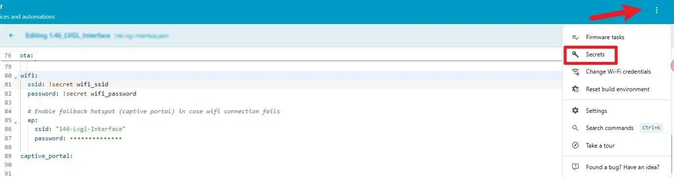
Click the three dots in the top right corner, then click "secret".
You can enter your own Wi-Fi name and password. (Make sure this Wi-Fi is on the same local network as your Home Assistant system.)

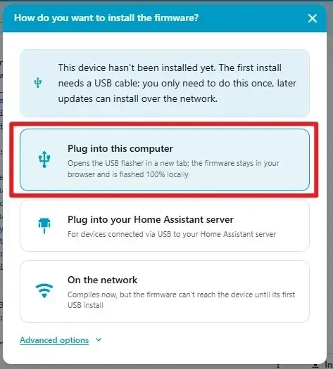
Click Install, select the USB installation method suitable for your current environment, choose the serial port corresponding to the CrowPanel, and complete compilation and flashing. After flashing finishes, open the log window and confirm that the PCF8574, ST7701S display, Wi-Fi connection, and encoder initialize without repeated resets.

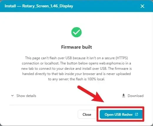
Wait for compilation.

After compilation completes, click "flash" to upload.
Select the connected serial port.

Click to connect to the corresponding serial port (confirm that the hardware is already connected).

Wait for the download to complete.

5. Hardware Operation Steps
With the device powered off, check that the screen, knob housing, and USB connector show no obvious damage, then use a USB cable that supports data transfer to connect the CrowPanel 2.1inch-HMI ESP32 Rotary Display to the computer.

Wait for the LVGL page to be built and look directly at the center of the round screen. The page should display Knob Screen Brightness and 50%. Rotate the knob clockwise and counterclockwise, adjusting back and forth near 0%, 50%, and 100%, and confirm that the on-screen percentage and backlight intensity change synchronously; the device should not freeze, restart, or stop refreshing for an extended period.

6. Key Code Explanation
6.1 Panel Power, Reset, and Startup Lock
on_boot:
  priority: 800
  then:
    - output.turn_on: lcd_power
    - output.turn_on: display_reset
    - delay: 100ms
    - output.turn_off: display_reset
    - delay: 100ms
    - delay: 500ms
    - light.turn_on:
        id: display_backlight
        brightness: 0.5
    - lambda: |-
        id(encoder_ready) = false;
        id(brightness_value) = 50;
        id(knob).publish_state(0);
    - light.turn_on:
        id: display_backlight
        brightness: 0.5
    - lambda: |-
        char buf[10];
        snprintf(buf, sizeof(buf), "%d%%", id(brightness_value));
        lv_label_set_text(id(lbl_brightness), buf);
    - delay: 200ms
    - lambda: |-
        id(encoder_ready) = true;
P3 and P4 on the PCF8574 power and reset the ST7701S panel. After the hardware settles, both the light entity and brightness_value are set to 50%. Publishing an encoder state of zero establishes a known baseline. The encoder remains locked until the final 200 ms delay has elapsed, preventing startup events from changing the initial value.
6.2 Shared Brightness State
globals:
  - id: brightness_value
    type: int
    restore_value: false
    initial_value: "50"
  - id: encoder_ready
    type: bool
    restore_value: false
    initial_value: "false"
brightness_value is the single percentage used by the PWM and LVGL label. encoder_ready separates initialization from normal input. Because neither value is restored from Flash, each restart returns to a predictable 50% state.
6.3 Encoder Pins and Filtering
sensor:
  - platform: rotary_encoder
    id: knob
    name: "Encoder"
    pin_a:
      number: 42
      mode:
        input: true
        pullup: true
    pin_b:
      number: 4
      mode:
        input: true
        pullup: true
    filters:
      - debounce: 20ms
      - lambda: return round(x);
    resolution: 1
    internal: true
The 2.1-inch board connects the encoder phases to GPIO42 and GPIO4. Pull-ups provide stable idle levels, the 20 ms debounce suppresses mechanical contact bounce, and round(x) keeps the callback on integer counts. internal: true hides the raw count from Home Assistant because it is only an input to the local brightness logic.
6.4 Direction, Range, PWM, and Label Update
if (!id(encoder_ready)) return;

static bool first_run = true;
static int last_encoder = 0;
int current = (int) id(knob).state;

if (first_run) {
  last_encoder = current;
  first_run = false;
  return;
}

int delta = current - last_encoder;
last_encoder = current;
if (delta == 0) return;

if (delta < 0) {
  id(brightness_value) += 5;
} else {
  id(brightness_value) -= 5;
}

if (id(brightness_value) < 0) id(brightness_value) = 0;
if (id(brightness_value) > 100) id(brightness_value) = 100;

float level = id(brightness_value) / 100.0f;
id(bl_pwm).set_level(level);

char buf[10];
snprintf(buf, sizeof(buf), "%d%%", id(brightness_value));
lv_label_set_text(id(lbl_brightness), buf);
lv_refr_now(NULL);
The first callback records a baseline without changing brightness. Later callbacks calculate delta; in the supplied 2.1 code, a negative delta adds 5% and a positive delta subtracts 5%. The perceived clockwise direction depends on the physical encoder mounting, so verify it on the device rather than changing the signs in advance. The result is clamped to 0-100, converted to the 0.0-1.0 LEDC range, written to GPIO6 through bl_pwm, formatted as a percentage, and pushed to the LVGL label.
6.5 ST7701S Display and LVGL Page
display:
  - platform: st7701s
    id: my_display
    update_interval: 50ms
    dimensions:
      width: 480
      height: 480
    pclk_frequency: 18MHz
    pclk_inverted: true

lvgl:
  displays:
    - my_display
  buffer_size: 50%
  widgets:
    - label:
        align: CENTER
        id: lbl_title
        y: 0
        text_font: montserrat_28
        text: "Knob Screen Brightness"
    - label:
        align: CENTER
        id: lbl_brightness
        y: 50
        text_font: montserrat_48
        text: "50%"
The full YAML contains the complete ST7701S initialization sequence and RGB pin map from Lesson 02. LVGL allocates a 50% draw buffer and places the title and percentage around the screen center. The callback updates lbl_brightness, so that ID must remain consistent.
7. Experimental Observations
At boot, the panel should stabilize at 50% brightness and show Knob Screen Brightness with 50%. Rotate the knob in both directions and confirm that the percentage changes in 5% steps and the physical backlight follows it. At 0% and 100%, further movement in the same direction must leave the value at the limit. The device should remain responsive during both slow and fast rotation.