All-in-one_Starter_Kit_for_ESP32-P4 AI Voice Chat Robot
Introduction
In this example, we’ll walk through the process step by step to show how to configure an AI voice chat robot on the All-in-one_Starter_Kit_for_ESP32-P4.
To enable voice conversations, the system needs three essential hardware components:
- A display to show the user interface
- A microphone to capture voice input
- A speaker to play back the AI’s responses
In this lesson, we’ll configure each of these components, including the display output, audio input, and audio output settings. These configurations will provide the foundation needed to build a complete AI voice interaction system.
Learning Goals
- Understand how an AI voice chat robot works
- Learn how to configure the display on the All-in-one_Starter_Kit_for_ESP32-P4
- Learn how to configure the microphone on the All-in-one_Starter_Kit_for_ESP32-P4
- Learn how to configure the speaker on the All-in-one_Starter_Kit_for_ESP32-P4
- Learn how to configure Wi-Fi on the All-in-one_Starter_Kit_for_ESP32-P4
Preview of the Result
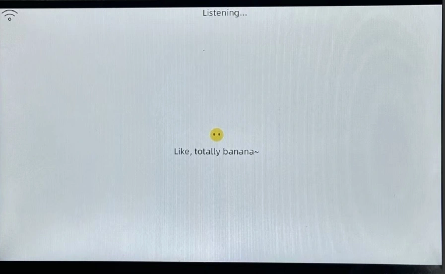
After uploading the code, you can wake up the AI robot using a predefined wake word and start having a conversation with it.
For detailed instructions, please refer to the All in one for P4 AI Case User Guide.
Hardware Used in This Lesson
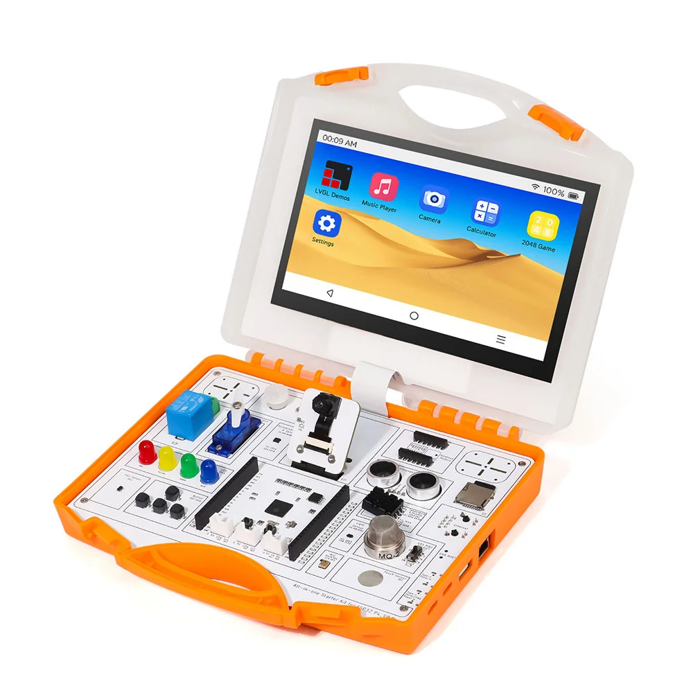
AI Voice Chat Robot
Download the Code
Before diving into the code explanation, you can download the complete project first.
Full project download link: https://github.com/Elecrow-RD/All-in-one-Starter-Kit-for-ESP32-P4-with-Common-Board-design/tree/master/example/AI%20Projects
Key Code Explanation
Now let’s go through the AI Voice Chat Robot example.
In the project directory, navigate to:
main → boards → elecrow-p4-board
Open the file:
config.h
This file is the main configuration file for the all in one for P4 development board. Below is an explanation of the key configuration settings.
Audio Configuration
Both the audio input sampling rate and audio output sampling rate are set to 16,000 Hz.
I2S Audio Pin Configuration
#define AUDIO_I2S_GPIO_MCLK GPIO_NUM_NC
#define AUDIO_I2S_GPIO_WS   GPIO_NUM_21
#define AUDIO_I2S_GPIO_BCLK GPIO_NUM_22
#define AUDIO_I2S_GPIO_DOUT GPIO_NUM_23
- MCLK (Master Clock) is not used and is set to NC.
- WS / LRCLK (Word Select) controls the left and right audio channels and is connected to GPIO21.
- BCLK (Bit Clock) controls the timing of each audio data bit and is connected to GPIO22.
- DOUT outputs audio data to the speaker and is connected to GPIO23.
Microphone Pin Configuration
- PDM microphone clock output: GPIO3
- PDM microphone data input: GPIO4
Button Configuration
This is the BOOT button on the all in one for P4 board, which can be used to interrupt the AI conversation.
Display Configuration
#define DISPLAY_WIDTH 1024
#define DISPLAY_HEIGHT 600
#define LCD_BIT_PER_PIXEL (16)
#define PIN_NUM_LCD_RST GPIO_NUM_5
- Display resolution: 1024 × 600
- Pixel format: 16-bit (RGB565)
- The LCD reset pin is GPIO_NUM_5.
MIPI DSI Configuration
- Power-on initialization delay: 3000 ms
- Number of data lanes: 2
MIPI DSI Power Configuration
- LDO channel: 3
- Power supply voltage: 2.5 V
Display Orientation Configuration
#define DISPLAY_SWAP_XY false
#define DISPLAY_MIRROR_X false
#define DISPLAY_MIRROR_Y false
#define DISPLAY_OFFSET_X 0
#define DISPLAY_OFFSET_Y 0
- No XY axis swapping
- No horizontal mirroring
- No vertical mirroring
- X offset: 0
- Y offset: 0
Backlight Configuration
- Backlight control pin: GPIO20
- Backlight output is not inverted
Touch Screen Configuration (Not Used in This Example)
- Touch reset pin: GPIO40
- Touch interrupt pin: GPIO39
Camera Configuration
Key configuration parameters:
#define CAMERA_I2C_PORT         I2C_NUM_1    // I2C port number
#define CAMERA_I2C_SCL_PIN      GPIO_NUM_46  // Camera I2C SCL pin
#define CAMERA_I2C_SDA_PIN      GPIO_NUM_45  // Camera I2C SDA pin
- SCCB port: 1
- SCL pin: GPIO46
- SDA pin: GPIO45
Hardware Implementation File
Under the same path:
main → boards → elecrow-p4-board
you will also find the file:
elecrow_board.cc
This file implements the core hardware functions of the all in one for P4 system.
It defines a complete device configuration with Wi-Fi support, including:
- Display
- Backlight
- Camera
- Buttons
- Touch communication
All of these components are explained in the all in one for P4 basic course, so they will not be covered in detail here.
Course Links:
Version 1.0:
Version 1.1:
Important Pin Configuration
Check the corresponding settings in the sdkconfig file:
CONFIG_ESP_HOSTED_CP_TARGET_ESP32C6=y
# CONFIG_ESP_HOSTED_CP_TARGET_ESP32H2 is not set
# CONFIG_ESP_HOSTED_CP_TARGET_ESP32H4 is not set
CONFIG_ESP_HOSTED_PRIV_ENABLE_WIFI_OPTIONS=y

#
# ESP32-C6 is Co-processor Target from Wi-Fi Remote Component
#
CONFIG_ESP_HOSTED_IDF_SLAVE_TARGET="esp32c6"
CONFIG_ESP_HOSTED_P4_DEV_BOARD_NONE=y
# CONFIG_ESP_HOSTED_P4_DEV_BOARD_FUNC_BOARD is not set
# CONFIG_ESP32P4_EYE_C6_BOARD is not set
# CONFIG_ESP_HOSTED_P4_C6_CORE_BOARD is not set
CONFIG_ESP_HOSTED_PRIV_SDIO_OPTION=y
CONFIG_ESP_HOSTED_PRIV_SPI_HD_OPTION=y
# CONFIG_ESP_HOSTED_SPI_HOST_INTERFACE is not set
CONFIG_ESP_HOSTED_SDIO_HOST_INTERFACE=y
# CONFIG_ESP_HOSTED_SPI_HD_HOST_INTERFACE is not set
# CONFIG_ESP_HOSTED_UART_HOST_INTERFACE is not set

#
# Hosted SDIO Configuration
#
CONFIG_ESP_HOSTED_SDIO_RESET_ACTIVE_HIGH=y
# CONFIG_ESP_HOSTED_SDIO_RESET_ACTIVE_LOW is not set
# CONFIG_ESP_HOSTED_SDIO_OPTIMIZATION_RX_NONE is not set
# CONFIG_ESP_HOSTED_SDIO_OPTIMIZATION_RX_MAX_SIZE is not set
CONFIG_ESP_HOSTED_SDIO_OPTIMIZATION_RX_STREAMING_MODE=y
# CONFIG_ESP_HOSTED_SDIO_SLOT_0 is not set
CONFIG_ESP_HOSTED_SDIO_SLOT_1=y
CONFIG_ESP_HOSTED_SDIO_SLOT=1
# CONFIG_ESP_HOSTED_SD_PWR_CTRL_LDO_INTERNAL_IO is not set
CONFIG_ESP_HOSTED_SDIO_4_BIT_BUS=y
# CONFIG_ESP_HOSTED_SDIO_1_BIT_BUS is not set
CONFIG_ESP_HOSTED_SDIO_BUS_WIDTH=4
CONFIG_ESP_HOSTED_SDIO_CLOCK_FREQ_KHZ=40000
CONFIG_ESP_HOSTED_PRIV_SDIO_PIN_CMD_SLOT_1=15
CONFIG_ESP_HOSTED_PRIV_SDIO_PIN_CLK_SLOT_1=14
CONFIG_ESP_HOSTED_PRIV_SDIO_PIN_D0_SLOT_1=7
CONFIG_ESP_HOSTED_PRIV_SDIO_PIN_D1_4BIT_BUS_SLOT_1=9
CONFIG_ESP_HOSTED_PRIV_SDIO_PIN_D2_4BIT_BUS_SLOT_1=10
CONFIG_ESP_HOSTED_PRIV_SDIO_PIN_D3_4BIT_BUS_SLOT_1=11
CONFIG_ESP_HOSTED_SDIO_GPIO_RESET_SLAVE=2
CONFIG_ESP_HOSTED_SDIO_PIN_CMD=15
CONFIG_ESP_HOSTED_SDIO_PIN_CLK=14
CONFIG_ESP_HOSTED_SDIO_PIN_D0=7
CONFIG_ESP_HOSTED_SDIO_PRIV_PIN_D1_4BIT_BUS=9
CONFIG_ESP_HOSTED_SDIO_PIN_D2=10
CONFIG_ESP_HOSTED_SDIO_PIN_D3=11
CONFIG_ESP_HOSTED_SDIO_PIN_D1=9
CONFIG_ESP_HOSTED_SDIO_TX_Q_SIZE=20
CONFIG_ESP_HOSTED_SDIO_RX_Q_SIZE=20
CONFIG_ESP_HOSTED_SDIO_RESET_DELAY_MS=1500
For reliability, it is recommended to copy these configuration settings directly into menuconfig.
Once configured, the sdkconfig file will automatically generate the corresponding settings.