2.4_2.8inch_Lesson06_nRF24L01_Communication
1. Course Introduction
This lesson uses two CrowPanel Advance 2.4/2.8-inch development boards and two nRF24L01 wireless modules to implement two-device communication: one board acts as the transmitter and periodically sends fixed text, while the other acts as the receiver and displays the received content on both the serial monitor and the screen.
This lesson is best suited for practicing the complete thought process behind "paired communication." Looking at only one side makes it hard to tell whether the problem lies in transmission, reception, or an address mismatch—examining both sides together makes things much clearer.
2. Learning Objectives
- Be able to correctly configure the address, channel, and data rate for both the transmitter and the receiver
- Understand the difference between
openWritingPipe()andopenReadingPipe() - Determine whether the wireless link is functioning properly based on the serial log and the on-screen display
3. What You Need
- Two CrowPanel Advance 2.4/2.8-inch development boards
- Two nRF24L01 wireless modules
- Two USB data cables that support data transfer
- Arduino IDE
- Lesson code:
RF24_WRITE_2_4_2_8.inoRF24_READ_2_4_2_8.ino
Code and Resource Download
Code download:
Transmitting end code:
Receiving end code:
4. Software Operation Steps
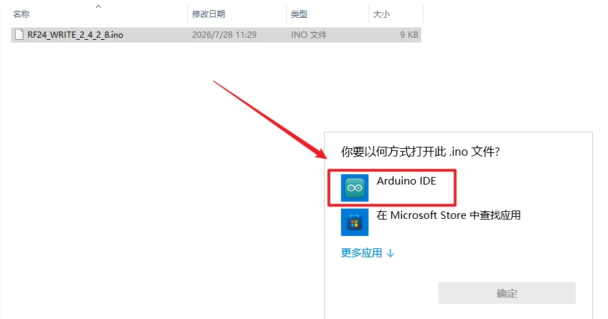
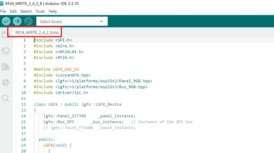
Open the project RF24_WRITE_2_4_2_8 in the Arduino IDE and confirm that the code file has been opened.
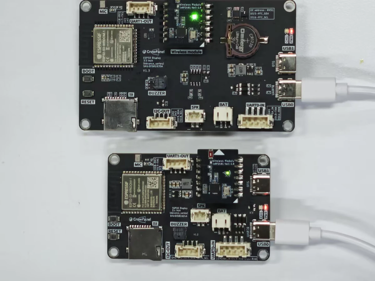
As required by the project, insert the nRF24L01 module into the W-M wireless module slot on the CrowPanel Advance 2.4-inch development board. Use one board as the transmitter and the other as the receiver, and connect the development boards to your computer using USB cables that support data transfer.
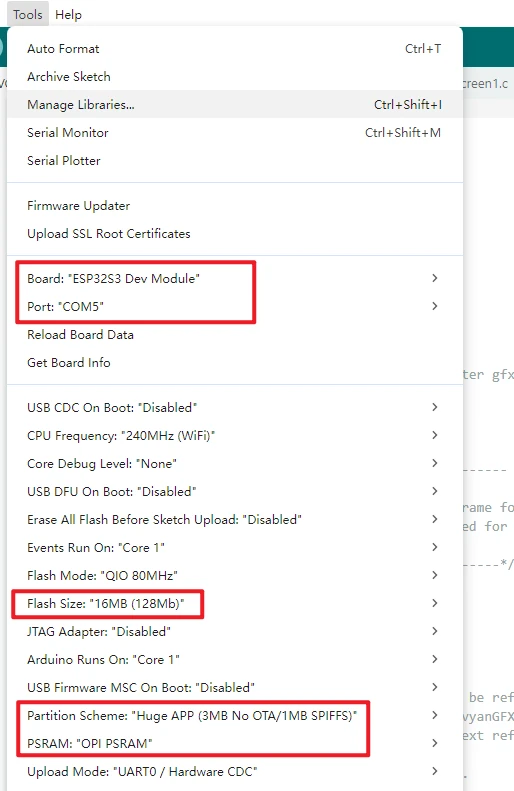
Configure the Arduino IDE. The common settings are as follows:
-
Board:ESP32S3 Dev Module -
Port: Select the serial port corresponding to the current development board -
Flash Size:16MB (128Mb) -
PSRAM:OPI PSRAM -
Partition Scheme:Huge APP (3MB No OTA/1MB SPIFFS)
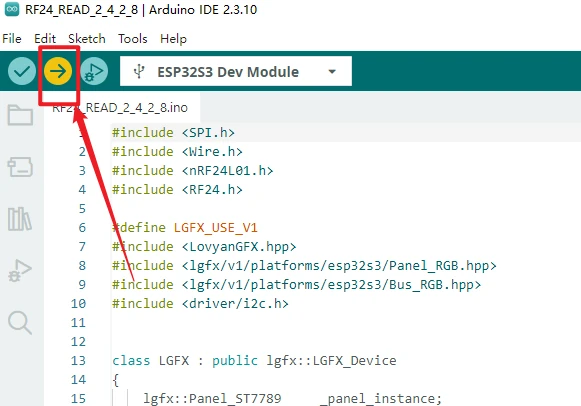
Click Upload to flash the transmitter program onto the first board.
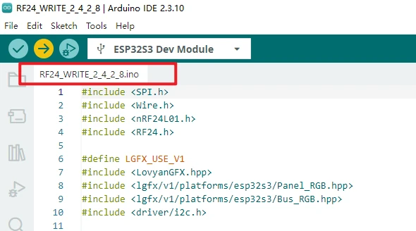
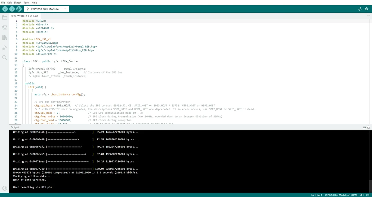
Insert the other nRF24L01 module into the W-M wireless module slot on the development board, then open the receiver project READ/RF24_READ_2_4_2_8 and repeat the same configuration and flashing process.
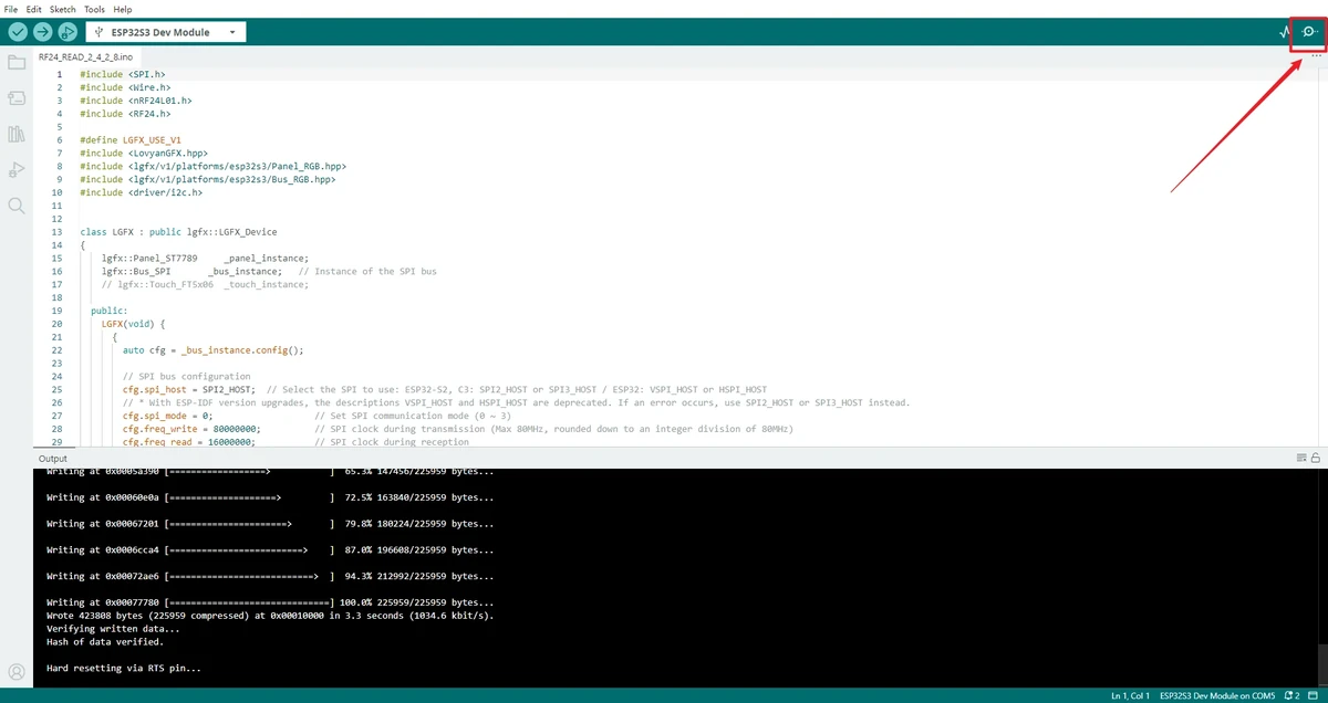
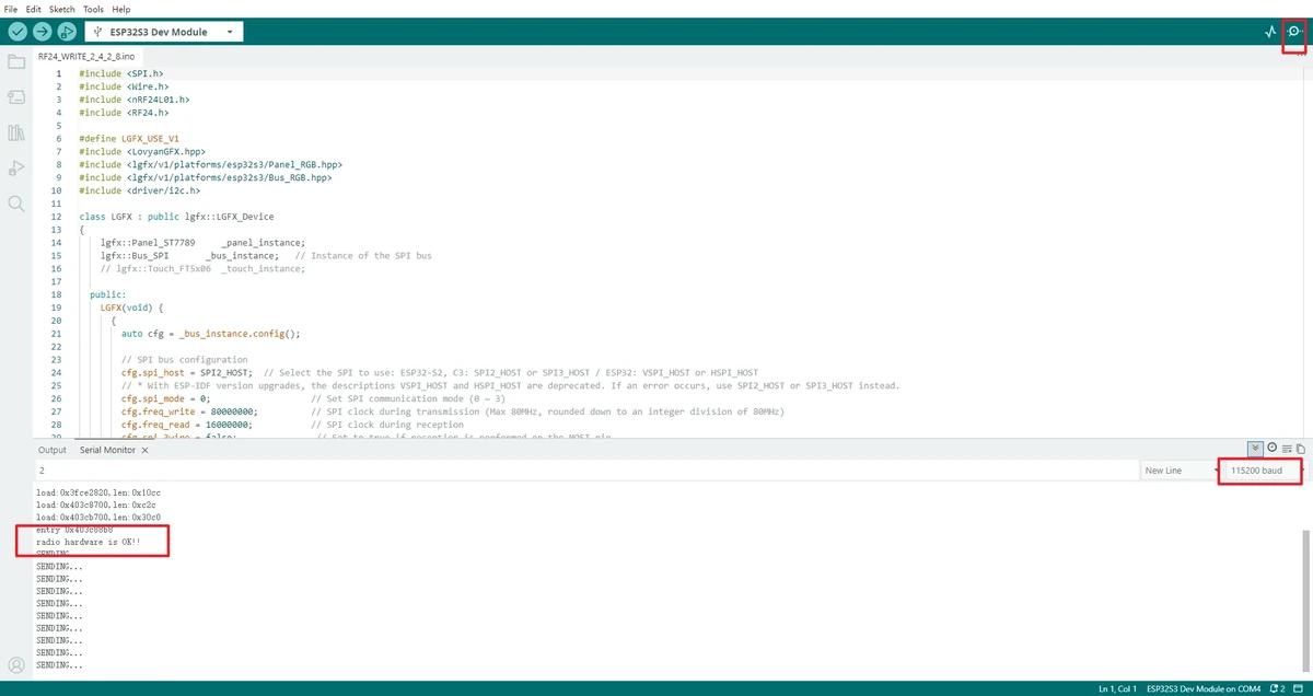
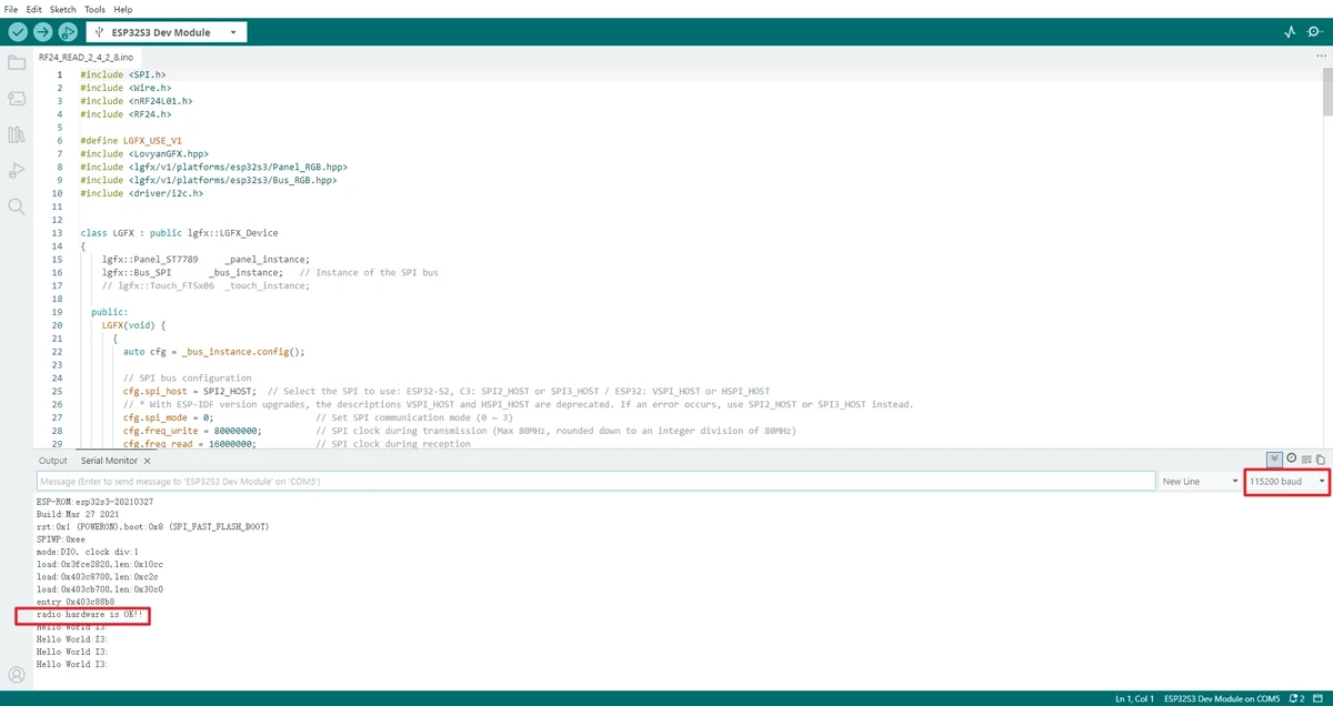
After flashing is complete, open the Serial Monitor, set the baud rate to 115200, and observe whether SENDING... or received content is output.
RF24_WRITE:
RF24_READ:
5. Hardware Connection Steps
- As required by the project, insert the nRF24L01 module into the W-M wireless module slot on the development board.
- Prepare two boards, using one as the transmitter and the other as the receiver.
- Connect both boards with USB data cables to ensure a stable power supply.
- After connecting the modules and boards, observe the operating status of the transmitter and receiver respectively.
Note: If you find that the board behaves abnormally during flashing, remove the wireless module before uploading the program, and reinsert it only after confirming that the program has been written successfully.
6. Key Code Explanation
6.1 Transmitter Core Configuration
radio.openWritingPipe(address);
radio.setPALevel(RF24_PA_MAX);
radio.setDataRate(RF24_250KBPS);
radio.setChannel(50);
radio.stopListening();
This code initializes the transmitter. openWritingPipe() sets the destination address, setDataRate() and setChannel() must match those on the receiver, and stopListening() puts the module into transmit mode.
6.2 Receiver Core Configuration
radio.openReadingPipe(0, address);
radio.setPALevel(RF24_PA_MAX);
radio.setDataRate(RF24_250KBPS);
radio.setChannel(50);
radio.startListening();
This code initializes the receiver. If even one of the address, channel, and data rate differs, the transmitter may operate normally while the receiver fails to receive any data.
6.3 Data Transmission and Reception
The transmitter sends a string via radio.write(), while the receiver uses radio.available() to check whether data is present, then uses radio.read() to retrieve the content.
7. Experimental Results
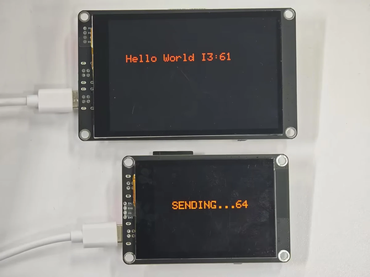
After flashing is complete and the wireless modules are properly inserted, the transmitter's serial port will continuously output SENDING..., and the receiver's serial port and screen will display the received string content.
If no data is received, check the following items first:
- Whether the addresses of the two boards are consistent
- Whether the channels are consistent
- Whether the data rates are consistent
- Whether the nRF24L01 module is properly inserted
- Whether both boards are properly powered
8. Code Download
- Transmitting end Code download link: RF24_WRITE_2_4_2_8
- Receiving end Code download link: RF24_READ_2_4_2_8