ThinkNode M9 Meshtastic Communication Terminal with Full Keyboard
Document version: 2026-08-26
Applicable device: Elecrow ThinkNode M9 V1.0
Applicable software: the Meshtastic firmware and on-device interface shown in this guide. Menu names and behavior may change with firmware updates.
Table of Contents
- 1. Product Introduction
- 1.1 Product Overview
- 1.2 Safety Information and Package Contents
- 1.3 Hardware Architecture and Specifications
- 1.4 Official Resources
- 2. Product Pinout
- 2.1 Main ESP32-S3 GPIO Summary
- 2.2 LR1110 LoRa
- 2.3 LCD
- 2.4 microSD/TF Card
- 2.5 GNSS
- 2.6 RTC and Sensors
- 2.7 Keyboard Subsystem
- 2.8 Other Hardware Signals
- 3. Meshtastic Operation
- 3.1 Controls and First Start
- 3.2 Home Page
- 3.3 Node List
- 3.4 Group Channels and Chat
- 3.5 Map and Positioning
- 3.6 Settings and Tools
- 3.7 Connect to the Meshtastic App
- 3.8 Radio, Channel, and Role Configuration
- 3.9 Firmware, Storage, and Maintenance
- 3.10 Troubleshooting
1. Product Introduction
1.1 Product Overview
ThinkNode M9 is a standalone Meshtastic communication terminal in a phone-like form factor. Its display, full keyboard, LoRa radio, positioning, battery, and local user interface allow it to exchange messages and locations without requiring a phone for everyday use. A phone can still be connected when the Meshtastic app is needed for advanced configuration or management.
The device integrates an ESP32-S3, Semtech LR1110, GNSS, a 2.4-inch color LCD, microSD storage, RTC, magnetic and motion sensors, Wi-Fi, Bluetooth, a buzzer, and a dedicated ESP32-S2 keyboard controller.
Typical uses include:
- Off-grid text communication where cellular service is unavailable;
- Hiking, camping, event coordination, and emergency preparedness;
- Meshtastic group-channel and direct-message communication;
- GNSS positioning, location sharing, and offline map viewing;
- Node, signal, route, and packet diagnostics from the device.
1.2 Safety Information and Package Contents
1.2.1 Safety Information
- Install a LoRa antenna matched to the hardware frequency band before powering on or transmitting.
- Select the correct Meshtastic Region for the country or territory in which the device is used. Frequency, bandwidth, duty cycle, and transmit power must comply with local regulations.
- Do not share private channel keys, Bluetooth pairing codes, Wi-Fi credentials, or precise location data publicly.
- Keep the battery adequately charged during firmware updates. Do not disconnect power or remove the microSD card while an update or storage operation is in progress.
- Install only firmware explicitly built for ThinkNode M9. A generic ESP32-S3 Meshtastic image may use a different pin map and can leave the screen, radio, keyboard, GNSS, or power controls unusable.
- The LCD, microSD card, and LR1110 share one SPI bus. Custom firmware must keep all non-target chip-select signals inactive.
1.2.2 Package Contents
- ThinkNode M9 unit;
- USB-C data/charging cable;
- ThinkNode M9 starter card;
- Antenna and other accessories included with the purchased bundle.
Check the actual sales package against the seller's packing list, as bundle contents may vary.
1.3 Hardware Architecture and Specifications
1.3.1 Key Specifications
| Item | ThinkNode M9 V1.0 |
|---|---|
| Main controller | ESP32-S3-R8, dual core, up to 240 MHz |
| Keyboard controller | ESP32-S2 |
| LoRa transceiver | Semtech LR1110 |
| GNSS | ATGM336H-5NR32 / BM72A |
| Display | 2.4-inch color TFT LCD, 320 × 240 |
| RTC | PCF8563 |
| Magnetic sensor | QMC6309 |
| Motion sensor | QMI8658B |
| Onboard flash | ZD25Q128, 128 Mbit (16 MB) NOR Flash |
| Storage expansion | microSD/TF |
| Wireless connectivity | 2.4 GHz Wi-Fi, Bluetooth, LoRa |
| Battery | 2300 mAh rechargeable lithium battery |
| Charging/data | USB-C |
The source manual states "16GB Storage." The V1.0 schematic identifies a ZD25Q128 device, which is 128 Mbit (16 MB). Storage available to the user can also depend on the installed microSD card.
1.3.2 Hardware Block Diagram
                       +-------------------+
USB-C -- CH340K ------>|                   |<------ Wi-Fi / Bluetooth
                       |   ESP32-S3-R8 U9   |
GNSS UART/PPS -------->|                   |<-- I2C --> RTC
                       |                   |<-- I2C --> QMC6309 + QMI8658B
                       +---------+---------+
                                 |
                  shared SPI: SCK/MOSI/MISO
                    +------------+------------+
                    |            |            |
                 LR1110        LCD          microSD
                 own NSS       own CS       own CS

ESP32-S2 U10 <---- SDA/SCL + WAKEUP ----> ESP32-S3 U9
      |
      +---- keyboard matrix, shortcut keys, and keyboard LED
1.4 Official Resources
- Elecrow official website
- Meshtastic official website
- Meshtastic documentation
- Meshtastic web flasher
- Meshtastic downloads
2. Product Pinout
2.1 Main ESP32-S3 GPIO Summary
On the ESP32-S3 symbol, MTCK/MTDO/MTDI/MTMS correspond to GPIO39/GPIO40/GPIO41/GPIO42; SPICLK_P/SPICLK_N correspond to GPIO47/GPIO48; and XTAL_32K_P/XTAL_32K_N correspond to GPIO15/GPIO16.
| Schematic Net | ESP32-S3 GPIO | Purpose |
|---|---|---|
IO0_BOOT | GPIO0 | Main-controller BOOT |
5V_TEST | GPIO1 | 5 V detection/test net |
GPS_TX | GPIO2 | Main controller receives GNSS TX |
GPS_RX | GPIO3 | Main controller transmits to GNSS RX |
1PPS_TEST | GPIO4 | GNSS 1PPS |
GPS_RST1 | GPIO5 | GNSS reset control |
SCL | GPIO6 | RTC/sensor I2C SCL |
SDA | GPIO7 | RTC/sensor I2C SDA |
DONE | GPIO8 | Power/charging status net |
BUZZER_EN | GPIO9 | Buzzer enable |
GPS_ON/OFF | GPIO10 | GNSS on/off control |
GPS_EN | GPIO11 | GNSS power enable |
ESP32_WAKEUP | GPIO12 | Keyboard coprocessor wakes main controller |
BAT_ADC | GPIO13 | Battery-voltage ADC |
LCD_RESET | GPIO14 | LCD reset |
LCD_RS | GPIO15 | LCD RS/DC |
LCD_CS | GPIO16 | LCD chip select |
BL_EN | GPIO17 | LCD backlight enable |
VDD_PERIPH_EN | GPIO18 | Peripheral power enable |
LCD_TE | GPIO19 | LCD tearing-effect signal |
ESP32-2_SDA | GPIO20 | Keyboard-coprocessor data line |
ESP32-2_SCL | GPIO21 | Keyboard-coprocessor clock line |
ESP32_MISO | GPIO38 | Shared SPI MISO |
LR_NSS | GPIO39 | LR1110 chip select/NSS |
ESP32_SCK | GPIO40 | Shared SPI SCK |
LR_BUSY | GPIO41 | LR1110 BUSY |
INTERRUPT | GPIO42 | LR1110 interrupt |
LR_NRESET | GPIO45 | LR1110 reset |
KEY_LED | GPIO46 | Keyboard-light control net |
ESP32_MOSI | GPIO47 | Shared SPI MOSI |
SD_CS | GPIO48 | microSD chip select |
2.2 LR1110 LoRa
| LR1110 Signal | ESP32-S3 GPIO | Description |
|---|---|---|
LR_NSS / DIO1 | GPIO39 | SPI chip select; LR1110 SPI signals are labeled DIO1-DIO4 in the schematic |
ESP32_SCK / DIO2 | GPIO40 | SPI clock |
ESP32_MOSI / DIO3 | GPIO47 | Controller out/peripheral in |
ESP32_MISO / DIO4 | GPIO38 | Controller in/peripheral out |
LR_BUSY / DIO0 | GPIO41 | Busy status |
INTERRUPT / DIO9 | GPIO42 | Interrupt |
LR_NRESET / NRESET | GPIO45 | Reset |
| DIO7, DIO8 | Not connected to main-controller GPIO | Reserved nets in the schematic |
2.3 LCD
| LCD Signal | ESP32-S3 GPIO | FPC J6 |
|---|---|---|
LCD_RESET | GPIO14 | 1 |
LCD_RS | GPIO15 | 2 |
ESP32_SCK | GPIO40 | 3 |
LCD_CS | GPIO16 | 5 |
DISPLAY_VDD | Power | 6, 7 |
LCD_TE | GPIO19 | 8 |
ESP32_MOSI | GPIO47 | 9 |
| GND | - | 10, 13, 14 |
LCD_A / LCD_K | Backlight circuit | 11, 12 |
BL_EN | GPIO17 | Backlight MOS control; not a direct FPC logic signal |
2.4 microSD/TF Card
| TF Signal | ESP32-S3 GPIO | Description |
|---|---|---|
SD_CS / CD-DAT3 | GPIO48 | Chip select |
ESP32_SCK / CLK | GPIO40 | Shared SPI clock |
ESP32_MOSI / CMD | GPIO47 | Shared SPI MOSI |
ESP32_MISO / DAT0 | GPIO38 | Shared SPI MISO |
SD_3V3 | - | Card power |
SPI rule: before initializing or accessing a peripheral, ensure that only the target peripheral's CS is low among LR1110 NSS, LCD CS, and SD CS. Keep all other CS signals high.
2.5 GNSS
| GNSS Signal | ESP32-S3 GPIO | Description |
|---|---|---|
GPS_TX | GPIO2 | GNSS TX → ESP32 RX |
GPS_RX | GPIO3 | ESP32 TX → GNSS RX |
1PPS_TEST | GPIO4 | Pulse per second |
GPS_RST1 | GPIO5 | Reset control |
GPS_ON/OFF | GPIO10 | Module ON/OFF |
GPS_EN | GPIO11 | Power enable |
GPS_BAT | Backup power | Preserves ephemeris/RTC state |
2.6 RTC and Sensors
| Module | Bus/Signal | ESP32-S3 GPIO | Notes |
|---|---|---|---|
| PCF8563 RTC | SCL | GPIO6 | RTC I2C net |
| PCF8563 RTC | SDA | GPIO7 | RTC I2C net |
| QMC6309 | 3D_SCL | GPIO6 through R44 | Shares sensor I2C bus with QMI8658B |
| QMC6309 | 3D_SDA | GPIO7 through R47 | Magnetometer |
| QMI8658B | 3D_SCL | GPIO6 through R44 | Motion sensor |
| QMI8658B | 3D_SDA | GPIO7 through R47 | CS high and SDO/SA0 grounded; I2C mode |
| Peripheral power | VDD_PERIPH_EN | GPIO18 | Enables sensor/LCD-related peripheral power |
2.7 Keyboard Subsystem (ESP32-S2 U10)
The keyboard matrix is scanned by a separate ESP32-S2. It communicates with the main controller through ESP32-2_SDA/SCL and can wake the main controller.
| Function | ESP32-S2 GPIO |
|---|---|
| ROW1 / ROW2 / ROW3 / ROW4 / ROW5 | GPIO40 / GPIO42 / GPIO45 / GPIO9 / GPIO19 |
| COL1-COL5 | GPIO36 / GPIO37 / GPIO20 / GPIO21 / GPIO11 |
| COL6-COL10 | GPIO1 / GPIO2 / GPIO3 / GPIO4 / GPIO5 |
| KEY_INT | GPIO12 |
| Main-controller SDA / SCL | GPIO7 / GPIO6 |
| Wake line | GPIO8 |
| Keyboard light | GPIO41 |
| Coprocessor BOOT | GPIO0 |
Dedicated keys are also connected to GPIO18, GPIO10, GPIO39, GPIO38, GPIO33, and GPIO34. In custom firmware, use the keyboard firmware and schematic switch identifiers; do not interpret these as ESP32-S3 GPIO values.
2.8 Other Hardware Signals
| Function | GPIO/Device | Description |
|---|---|---|
| Buzzer | GPIO9 BUZZER_EN | Controlled through a driver transistor |
| Battery monitoring | GPIO13 BAT_ADC | Routed to ADC through a divider and filter |
| USB-UART | CH340K U3 | Serial communication and maintenance |
| RTC backup | PCF8563 + RTC_3V3 | Powered by the backup-power net |
| Charging | LGS4056HDA-4.35 U6 | Schematic charging-current formula: I=1000/R |
3. Meshtastic Operation
3.1 Controls and First Start
3.1.1 Before Power-On
- Install the correct antenna.
- Charge the battery using USB-C.
- Power on the M9 and wait for the Meshtastic home page.
- Confirm the Region before transmitting. Select the legally applicable region, not merely the region shown in the screenshots.
- For communication between devices, ensure that Region, modem preset, frequency slot/override, and channel settings are compatible.
3.1.2 Button Functions
| Button | Meshtastic Function |
|---|---|
| Home | Return to the Home page |
| Chat | Open the chat page |
| Messages/Menu | Open the chat dialog box |
| Navigation Up/Down/Left/Right | Move the cursor, highlight an item, scroll, or pan the map |
| Navigation center | Confirm or open the highlighted item |
| Back | Return to the previous level |
| Map | Open the map page |
| Positioning | Send a temporary position ping; hold for about 3 seconds to enable or disable GNSS |
| Reset | Restart the device |
| Full keyboard | Enter text; press Enter to send where supported |
The exact shortcut behavior may vary by firmware version. Follow labels shown on the current screen when they differ from this table.
3.2 Home Page
The Home page is a vertically scrollable status dashboard. The following screenshots show consecutive parts of the same page.
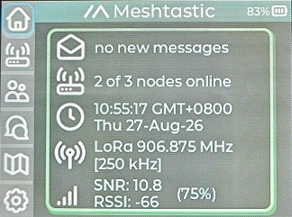
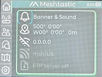
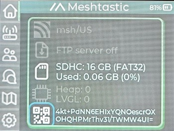
| Item | Description and Operation |
|---|---|
| Envelope | Shows unread messages; select it to enter chat |
| Nodes online | Shows nodes with previous communication records; select it to open the node list/filter page |
| Time | Select to toggle between current time and device uptime |
| LoRa frequency/region | Displays active radio information; the screenshot is an example only |
| SNR / RSSI | Signal-to-noise ratio and received-signal-strength indicators |
| Notification | Select to change the message-alert mode |
| Coordinates | Displays GNSS coordinates; press and hold to enable or disable GNSS |
| Wi-Fi | Press and hold to enable/disable Wi-Fi and open connection controls; map data can be downloaded after connection |
| MQTT | Press and hold to enable or disable MQTT when configured |
| FTP | Press and hold to enable or disable the FTP server |
| SD card | Shows whether a microSD card is detected |
| Heap / LVGL | Select to show or hide memory and graphics information |
| QR code | Select to display the device QR code |
RSSI and SNR describe a received packet or active link sample; they are not a guarantee that a new message has been delivered end to end.
3.3 Node List
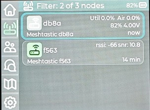
The node list shows Meshtastic nodes heard by this device. Depending on the information advertised by a node, an entry can include its long/short name, last-heard time, battery or power state, utilization, and other telemetry.
- Select a node once to view its available details.
- Press and hold a node to begin a direct message when supported by the current firmware.
- A node shown as online or recently heard has transmitted a packet received by the mesh; it does not mean that the node is currently reachable in both directions.
- Stale entries remain in the node database until they expire or are removed.
3.4 Group Channels and Chat
3.4.1 Group Channels
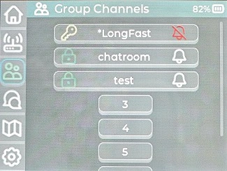
The Group Channels page lists configured channel slots. Select a channel to open its conversation. Channel interoperability depends on the complete channel configuration, not the displayed name alone.
For two devices to communicate on an encrypted channel, they must use compatible radio settings and the same channel name/key configuration. Share channel URLs or QR codes only through a trusted method because they may contain the encryption key.
3.4.2 Chat Window
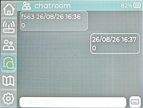
- Open a group channel or direct-message conversation.
- Select the text field and enter the message with the full keyboard.
- Press Enter or select the on-screen send control.
- Wait for the message state to update. A locally displayed outgoing message is not by itself proof of remote delivery.
Keep messages concise. LoRa has limited airtime and throughput, and long messages may be split into multiple packets. Avoid repeatedly sending the same message when the channel is busy.
3.5 Map and Positioning
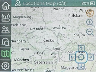
The map displays local or received Meshtastic positions over offline/online-downloaded tiles.
- Use the navigation keys to move the map cursor.
- Press
Sym+Oto zoom in. - Press
Sym+Ito zoom out. - Press and hold the navigation-center key to open map settings.
- In map settings, use the top control for brightness and the bottom control for contrast.
- Use the Positioning key or the map control to return to the device position when a valid GNSS fix is available.
Maps are preloaded on the factory microSD card when included with the product bundle. The firmware can also download map data while connected to Wi-Fi. If a replacement card is used, follow the directory and file-format requirements of the installed M9 firmware.
3.5.1 Obtaining a GNSS Fix
- Move outdoors with a clear view of the sky.
- Enable GNSS and keep the device stationary.
- Wait for valid coordinates and a current fix; a cold start may take several minutes.
- Verify that the displayed position is current before sending a location ping.
GNSS is not required for text messaging. Position packets can reveal sensitive location data, so review channel membership and position settings before enabling automatic sharing.
3.6 Settings and Tools
3.6.1 Settings
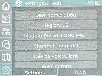
The Settings tab exposes common device and Meshtastic configuration, including user name, Region, modem preset, primary channel, device role, and Wi-Fi. Scroll to reach additional options such as alerts, language, reset, backup/restore, reboot/shutdown, and legal information.
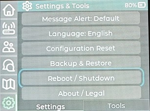
Changes take effect only after selecting
OK. Some changes require a restart. Record the original settings before changing radio or channel parameters.
3.6.2 Tools
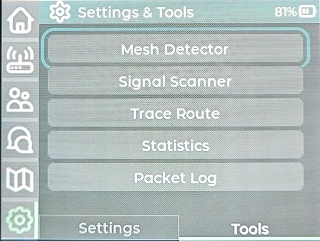
| Tool | Function |
|---|---|
| Mesh Detector | Periodically sends node-information requests to detect nearby nodes |
| Signal Scanner | Monitors signal strength for a selected node to assist with placement and testing |
| Trace Route | Performs route tracing for a selected node |
| Statistics | Breaks down received packets by type |
| Packet Log | Shows transmitted and received packet records |
Diagnostic tools create radio traffic. Use them sparingly, especially on busy meshes or in regions with strict duty-cycle limits.
3.7 Connect to the Meshtastic App
The M9 works independently, but the official Meshtastic app can be used for configuration, channel management, and node information.
- Install the official Meshtastic app from the downloads page, Apple App Store, or Google Play.
- On the M9, open
Settings & Tools → Settings → Reboot / Shutdown.
- Select the Bluetooth icon on the restart-mode page.
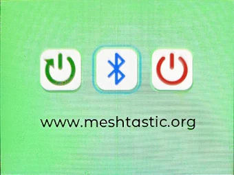
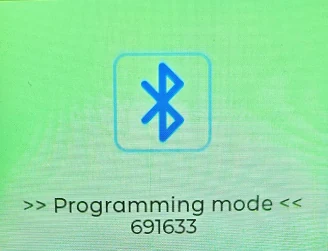
- After restart, the M9 displays
Programming modeand a temporary pairing number. To leave Bluetooth programming mode, press and hold the navigation-center key.
- Open the Meshtastic app, choose Bluetooth, and select the M9 from
Available devices.
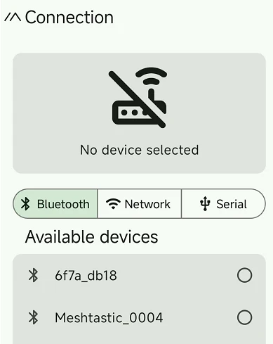
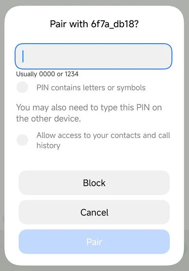
- Enter the pairing number currently shown on the M9, then confirm pairing.
- When pairing is complete, the app shows the connected device and signal strength.
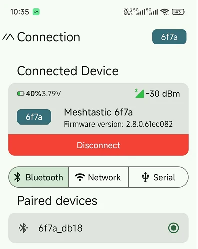
The pairing number in these screenshots is only an example. Always enter the number displayed by the device being paired. If the phone has an old pairing record, remove/forget it in both the Meshtastic app and the operating-system Bluetooth settings before trying again.
3.8 Radio, Channel, and Role Configuration
3.8.1 Region and Modem Preset
- Region applies the frequency plan and regulatory limits for a geographic jurisdiction. Select the location where the device is operating.
- Modem Preset controls LoRa bandwidth, spreading factor, coding rate, and related timing. Devices intended to communicate directly must use compatible settings.
- Frequency slot/override must remain compatible across the mesh. Leave advanced frequency overrides at their defaults unless the network plan requires otherwise.
The screenshots show EU_868, 906.875 MHz, and LONG_FAST examples. They are not globally applicable settings. Never copy a screenshot's Region or frequency without checking local rules and the hardware band.
3.8.2 Channels
Meshtastic supports a primary channel and additional secondary channels. The channel name is descriptive; the pre-shared key provides confidentiality. For successful communication, participating devices need the same relevant channel configuration and compatible radio settings.
- Treat channel QR codes and URLs as secrets if they contain private keys.
- Do not publish private position or telemetry data to a public/default channel.
- When a member should no longer have access, rotate the channel key and redistribute the new configuration securely.
3.8.3 Device Role
The CLIENT role is suitable for normal handheld use. Other roles change routing and power behavior. Select a router/repeater-style role only for a deliberately installed, continuously powered node with suitable placement and a configuration that follows current Meshtastic guidance. Using routing roles on every handheld can increase mesh congestion rather than improve coverage.
3.9 Firmware, Storage, and Maintenance
3.9.1 microSD and Maps
Use a reliable microSD card formatted as required by the current M9 firmware. Back up factory map data before replacing or reformatting the card. A missing or unreadable card can affect offline maps, logs, backups, and other storage-backed functions while basic LoRa messaging may continue to work.
3.9.2 Backup and Restore
Use Settings → Backup & Restore before major configuration changes or firmware updates. Protect backups because they can contain network names, channel configuration, and keys. After restoring, check Region and channel settings before transmitting.
3.9.3 Firmware Updates
Before updating:
- Charge the battery and keep the USB connection stable;
- Back up channels and important settings;
- Confirm that the release explicitly supports ThinkNode M9 V1.0 and its LR1110/display/keyboard pin map;
- Read the release notes and verify a checksum if one is published;
- Do not flash a generic build solely because it targets an ESP32-S3.
Use the firmware and flashing method published by Elecrow for the M9. The official Meshtastic web flasher is a reference tool, but the M9 must appear as a supported target or be accompanied by explicit M9 installation instructions before it is used.
3.10 Troubleshooting
3.10.1 No Nodes Are Found
- Confirm that both devices use the correct Region and compatible modem preset/frequency settings.
- Confirm that the antennas match the hardware band and are firmly attached.
- Place the devices nearby for the initial test and wait for periodic node-information packets.
- Confirm that neither device is in Bluetooth programming mode or shut down.
- Check Statistics and Packet Log for received traffic, RSSI, and SNR changes.
3.10.2 A Node Is Visible but Messages Are Not Exchanged
- Verify the primary/secondary channel slot, name, and key on both devices.
- Confirm compatible Region, modem preset, and frequency slot/override.
- Try a short message to the primary channel at close range.
- Do not treat an old node-list entry as proof that the node is currently online.
- Review Packet Log and Trace Route, but avoid repeated diagnostics on a busy channel.
3.10.3 Bluetooth Pairing Fails
- Re-enter Bluetooth programming mode from
Reboot / Shutdown. - Use the new number displayed on the M9; old pairing numbers expire.
- Remove the old M9 record from the app and the phone's Bluetooth settings.
- Grant the Meshtastic app the Bluetooth/nearby-device permissions required by the phone OS.
- Restart Bluetooth or reboot both devices, then retry at close range.
3.10.4 Wi-Fi Is Enabled but Online Features Do Not Work
The Wi-Fi icon can indicate that Wi-Fi is enabled without proving Internet connectivity. Verify the SSID and password, 2.4 GHz availability, assigned IP address, router restrictions, and Internet access. MQTT must also have valid server, authentication, and channel-uplink/downlink settings.
3.10.5 GNSS Has No Fix
Move outdoors, enable GNSS, and keep the device stationary with a clear sky view. A cold start may require several minutes. Confirm that the position is current before sharing it. Lack of a GNSS fix does not prevent basic LoRa text communication.
3.10.6 The Map Is Blank
- Confirm that the microSD card is detected and contains the expected map files;
- Connect to a working Wi-Fi network if the firmware downloads map tiles automatically;
- Check map coverage, zoom level, directory structure, and free storage space;
- Remember that a missing GNSS fix affects centering on the current position but should not prevent browsing existing tiles.
3.10.7 The microSD Card Is Not Detected
Power down before reseating the card. Test a known-good card of a supported capacity and file system. Back up data before reformatting. If custom firmware is used, also confirm that SD_CS is GPIO48 and that the shared SPI chip-select signals are managed correctly.
For initial acceptance testing, complete these checks in order: attach the correct antenna → select the legal Region → configure two units with the same modem preset and channel → verify node discovery → exchange short group messages → exchange a direct message → obtain an outdoor GNSS fix → verify map positioning → enter Bluetooth programming mode and connect the Meshtastic app → back up the working configuration.
How to Buy
Visit the Elecrow official website and search for ThinkNode M9 Meshtastic. Confirm the hardware frequency band and included accessories before ordering.
Support
For product support, use the contact options on the Elecrow website or email techsupport@elecrow.com. For general Meshtastic concepts and app usage, consult the official Meshtastic documentation.