Lesson03_CrowPanel_Rotary_Backlight: Adjusting Screen Brightness with the Rotary Knob
1. Course Introduction
Building on the basic display pipeline from Lesson 02, this lesson adds rotary knob input and PWM backlight control for the CrowPanel 1.28inch-HMI ESP32 Rotary Display. When the program starts, it sets the backlight to 50%, temporarily freezes the encoder events, and makes LVGL display Screen Brightness and 50%. After initialization completes, each valid rotation step increases or decreases the brightness by 5%, with the value clamped to the range of 0%–100%, and the on-screen percentage updates synchronously.
Learners will complete a full verification of the chain from "knob phase signal → ESPHome encoder count → brightness state → PWM output → LVGL label." This lesson does not use touch functionality, making it easier to independently determine whether knob direction, debounce filtering, and backlight changes are working correctly.
2. Learning Objectives
- Be able to explain how the A/B phases of a rotary encoder produce direction and count changes.
- Be able to explain why
encoder_readyblocks knob events during the startup phase. - Be able to explain the conversion relationship between integer brightness of 0%–100% and PWM output of 0.0–1.0.
- Be able to determine whether the dimming chain is correct through knob feel, the on-screen percentage, and the actual backlight.
- Be able to troubleshoot common issues such as reversed direction, skipped steps, unsynchronized values, and no backlight change.
3. What You Need to Prepare
- A CrowPanel 1.28inch-HMI ESP32 Rotary Display that has completed the basic display verification from Lesson 02.
- A USB data cable that supports data transfer.
- ESPHome Device Builder 1.9.2.
- ESPHome 2026.7.4.
Code download link: Elecrow Official Lesson_Code
4. Software Operation Steps
Step 01: Open ESPHome Device Builder 1.9.2 and confirm that its ESPHome Core version displays as 2026.7.4. If the versions do not match, complete the upgrade or switch the environment first to avoid component syntax differences. 
Step 02: Create a new project, place 128-adjust-screen-brightness.yaml into the ESPHome configuration directory, and open the corresponding configuration in the device list. However, device names on the same network must not be duplicated.
A. Click "Create device" to create a new project.


B. Select the ESP32-S3 main controller.

C. Name the project. Complete the new project task.

Step 03: Copy the official code into the project (the code is provided above).
However, make sure the project name in the code matches the name of the project you just created.

Step 04: Modify the Wi-Fi.

Click the three dots in the top right corner, then click "secret".
You can enter your own Wi-Fi name and password. (Make sure this Wi-Fi is on the same local network as your Home Assistant system.)


Step 05: Click Install, select the USB installation method suitable for your current environment, choose the serial port corresponding to the CrowPanel, and complete compilation and flashing. After flashing finishes, open the log window and you should see device startup and POWER ON logs.


Step 06: Wait for compilation.

Step 07: After compilation completes, click "flash" to upload.
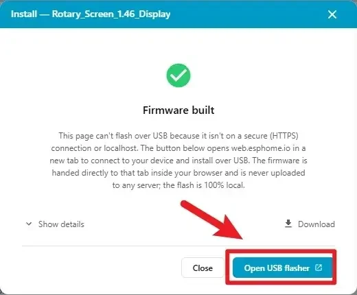
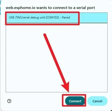
Step 08: Select the connected serial port.
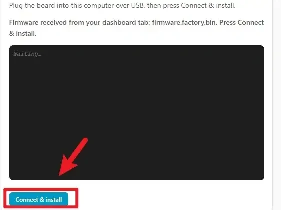
Step 09: Click to connect to the corresponding serial port (confirm that the hardware is already connected).
Step 10: Wait for the download to complete. 
5. Hardware Operation Steps
Step 01: With the device powered off, check that the screen, knob housing, and USB connector show no obvious damage, then use a USB cable that supports data transfer to connect the CrowPanel 1.28inch-HMI ESP32 Rotary Display to the computer.

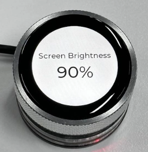
Step 02: Wait for the LVGL page to be built and look directly at the center of the round screen. The page should display Screen Brightness and 50%. Rotate the knob clockwise and counterclockwise, adjusting back and forth near 0%, 50%, and 100%, and confirm that the on-screen percentage and backlight intensity change synchronously; the device should not freeze, restart, or stop refreshing for an extended period.
6. Key Code Explanation
6.1 Freezing the Knob During Startup
on_boot:
  priority: 800
  then:
    - logger.log: "Backlight ON"
    - output.turn_on: gpio_3_backlight_pwm
    - delay: 200ms
    - output.turn_off: power_light
    - output.turn_on: out1
    - output.turn_on: out2
    - delay: 500ms
    - lambda: |-
        id(encoder_ready) = false;
        id(brightness_value) = 50;
        id(knob).publish_state(0);
    - light.turn_on:
        id: back_light
        brightness: 0.5
    - lambda: |-
        char buf[10];
        snprintf(buf, sizeof(buf), "%d%%", id(brightness_value));
        lv_label_set_text(id(lbl_brightness), buf);
        lv_refr_now(NULL);
    - delay: 200ms
    - lambda: |-
        id(encoder_ready) = true;
This segment preserves the complete startup sequence from the code. The device first turns on the GPIO46 backlight, waits 200 ms, then sets the three onboard outputs, then waits another 500 ms to allow the display component and LVGL to initialize. The program then disables encoder response, restores the brightness to 50, and publishes the encoder baseline of 0; back_light is set synchronously to 50%, and the label is immediately updated to 50%. Finally, after waiting another 200 ms, it sets encoder_ready to true.
The two delays serve different roles: the first waits for hardware and UI initialization, while the second ensures that publish_state(0) has finished propagating. If the encoder is enabled too early, the state events generated during initialization may be mistaken for rotation, causing the startup brightness to jump. Here, the same brightness_value is used to initialize both the backlight and the text, avoiding any startup desynchronization between the two.
6.2 The Role of the Global State
globals:
  - id: brightness_value
    type: int
    restore_value: false
    initial_value: "50"
  - id: encoder_ready
    type: bool
    restore_value: false
    initial_value: "false"
brightness_value drives both the PWM and the on-screen text, serving as the single source of brightness for this lesson. encoder_ready is only responsible for distinguishing between the two phases of "initializing" and "ready to respond to user input." Neither variable is written to Flash, so every reboot returns to 50%. If the brightness display and PWM were stored separately, it would be easy to run into the desynchronization issue where the UI shows 50% but the backlight is not actually at 50%.
6.3 Encoder Pins and Filtering
sensor:
  - platform: rotary_encoder
    id: knob
    name: "Encoder"
    pin_a:
      number: 45
      mode:
        input: true
        pullup: true
    pin_b:
      number: 42
      mode:
        input: true
        pullup: true
    resolution: 1
    filters:
      - debounce: 20ms
      - lambda: return round(x);
The complete sensor declaration shows that this lesson registers the knob as a rotary_encoder sensor named knob. GPIO45 and GPIO42 read the A/B phase signals, with internal pull-ups providing a stable default level for the mechanical contacts. resolution: 1 makes the count publish at the smallest effective step; the 20 ms debounce suppresses contact bounce, and then round(x) ensures the subsequent logic processes integer counts. A debounce that is too short may trigger multiple times per rotation, while one that is too long may drop steps during fast rotation.
6.4 The Complete Knob Event and Brightness Update Chain
    on_value:
      then:
        - lambda: |-
            if (!id(encoder_ready)) return;

            static bool first_run = true;
            static int last_encoder = 0;
            int current = (int) id(knob).state;

            if (first_run) {
              last_encoder = current;
              first_run = false;
              return;
            }

            int delta = current - last_encoder;
            last_encoder = current;
            if (delta == 0) return;

            if (delta < 0) {
              id(brightness_value) -= 5;
            } else {
              id(brightness_value) += 5;
            }

            if (id(brightness_value) < 0) id(brightness_value) = 0;
            if (id(brightness_value) > 100) id(brightness_value) = 100;

            float level = id(brightness_value) / 100.0f;
            id(gpio_3_backlight_pwm).set_level(level);

            char buf[10];
            snprintf(buf, sizeof(buf), "%d%%", id(brightness_value));
            lv_label_set_text(id(lbl_brightness), buf);
            lv_refr_now(NULL);
This is the complete continuous logic from input to output in the code. First it checks encoder_ready and exits directly if startup is not complete. first_run and last_encoder are static variables that retain their values across multiple callbacks; the first valid event only establishes the baseline and does not adjust the brightness. Subsequent events calculate delta, subtracting 5 for a negative value and adding 5 for a positive value.
The brightness is then clamped to 0–100 to prevent the PWM from receiving an invalid range. Dividing by the floating-point value 100.0f produces the 0.0–1.0 LEDC level, which is written directly to GPIO46. Finally, snprintf is used to generate text with a percent sign, update the LVGL label, and refresh immediately. Thus a single event completes, in order: "determine direction → modify state → clamp range → write backlight → update text."
6.5 Clamping the Range and Converting to PWM
if (id(brightness_value) < 0) id(brightness_value) = 0;
if (id(brightness_value) > 100) id(brightness_value) = 100;

float level = id(brightness_value) / 100.0f;
id(gpio_3_backlight_pwm).set_level(level);
Range clamping ensures the brightness is always a valid percentage. Dividing by 100.0f yields the 0.0–1.0 floating-point value required by the LEDC interface, where for example 50% corresponds to 0.5. The actual code calls gpio_3_backlight_pwm.set_level() directly to write to GPIO46, rather than calling the light component. If this is mistakenly written as integer division, 0%–99% may all compute to 0, manifesting as the screen suddenly going dark, with full brightness only restored at 100%.
6.6 Synchronously Updating the LVGL Label
char buf[10];
snprintf(buf, sizeof(buf), "%d%%", id(brightness_value));
lv_label_set_text(id(lbl_brightness), buf);
lv_refr_now(NULL);
The program converts the integer into a string with a %, then updates lbl_brightness. The forced refresh lets you see the new value immediately after the knob action. If the label update is removed, the backlight will still change, but the on-screen value will remain stuck at the old state; this contrast demonstrates that the PWM output and the LVGL display are two independent chains.
6.7 Display Driver and LVGL Page
spi:
  id: spi_bus
  mosi_pin: 11
  clk_pin: 10

display:
  - platform: ili9xxx
    id: round_display
    model: GC9A01A
    cs_pin: GPIO9
    dc_pin: GPIO3
    reset_pin: GPIO14
    invert_colors: true
    show_test_card: false
    rotation: 0
    update_interval: 10ms

lvgl:
  displays:
    - round_display
  buffer_size: 50%
  widgets:
    - label:
        align: CENTER
        id: lbl_title
        y: -30
        text_font: montserrat_22
        text: "Screen Brightness"
    - label:
        align: CENTER
        id: lbl_brightness
        y: 20
        text_font: montserrat_48
        text: "50%"
SPI uses GPIO11 and GPIO10, and the GC9A01A additionally uses GPIO9, GPIO3, and GPIO14 for chip select, command/data switching, and reset. The display updates every 10 ms, and LVGL uses a 50% buffer. The interface contains two consecutively defined labels, one above the other: the title is offset upward by 30 px and the percentage downward by 20 px. The event code updates exactly lbl_brightness, so this ID must not be renamed without synchronously modifying the Lambda.
7. Experimental Observations
When the device starts up, it first turns on the GPIO46 backlight output; after waiting 500 ms, the program initializes the brightness state and encoder count, then sets the backlight to 50% via back_light. The page displays Screen Brightness and 50%. It then waits another 200 ms before allowing knob events to be processed, so the initial count during startup will not mistakenly change the brightness.
When rotating clockwise, the percentage should increase by 5% and the backlight should gradually brighten; when rotating counterclockwise, the percentage should decrease by 5% and the backlight should gradually dim. After the value reaches 0% or 100%, continuing to rotate in the same direction keeps the displayed value at the boundary. During multiple fast and slow rotations, the device should not restart, and the label should not lag behind the actual brightness for an extended period.
8. Code Download
- Official code: Elecrow ESPHome Lesson_Code