Lesson04_CrowPanel_Touch_LVGL: Knob, Touch, and Brightness Meter Interface
1. Course Introduction
This lesson extends the circular display and knob dimming covered in the previous two lessons into a complete LVGL brightness meter interface. ESPHome scales bj_light_128_1.png to 240×240 and converts it into an RGB565 background image; LVGL then draws the title, a 0%–100% arc, and the brightness percentage on top of that background. Each knob step adjusts the value by 5%, with the GPIO46 PWM backlight, arc position, and text changing in sync.
Through this lesson, learners will validate the complete chain of on-board power, SPI display, PSRAM image resources, LVGL widgets, knob input, and PWM backlight. Because this lesson's code does not configure a touch component, lesson acceptance is based on knob dimming and interface synchronization.
2. Learning Objectives
- Be able to place
bj_light_128_1.pngin a location parseable by ESPHome and complete the image conversion. - Be able to explain the LVGL stacking relationship among the background image, arc, knob, and percentage label.
- Be able to use the knob to synchronously control the PWM, arc, and brightness text.
- Be able to troubleshoot missing resources, encoder anomalies, or PWM desynchronization issues based on the interface, logs, and backlight changes.
3. What You Need to Prepare
- CrowPanel 1.28inch-HMI ESP32 Rotary Display with Lesson01 and Lesson02 already completed.
- A USB data cable that supports data transfer.
- ESPHome Device Builder 1.9.2.
- ESPHome 2026.7.4.
- Lesson materials
bj_light_128_1.png / bj_light_128_2.png. - Network connection required to compile Google Fonts and download the materials.
Code download link: Elecrow Official Lesson_Code
Material download link:
Adding Materials Guide:
Next, we will show you how to upload the materials you want so that they can be used on the ESPHome platform.
First, download the Samba Share tool. You need to use this tool so that we can conveniently upload the image materials we want to use.
First, install Samba.


After the download completes, on this tool's page, configure your account. Here, configure the account name and password used by your Home Assistant.

After the configuration is complete, remember to click Save in the bottom-right corner.
Then you can open a file-viewing interface in your computer's file system and enter \ + your Home Assistant IP address.

After entering, you will arrive at your current ESPHome file management interface.

First enter the config folder, then enter the esphome folder.

You can place the materials you need to use here. In this way, the material names referenced in your code must also match the names of the materials you placed. (same operation)

This way, when your code is compiled, it will be able to find the materials you placed and display them on the screen.
4. Software Operation Steps
Step 01: Open ESPHome Device Builder 1.9.2 and confirm that its ESPHome Core version displays as 2026.7.4. If the versions are inconsistent, complete the upgrade or switch environments first to avoid component syntax differences. 
Step 02: Create a new project, place 128-lvgl-interface.yaml into the ESPHome configuration directory, and open the corresponding configuration in the device list. Note, however, that device names on the same network must not be duplicated.
A. Click Create device to create a new project.


B. Select the esp32s3 main controller.
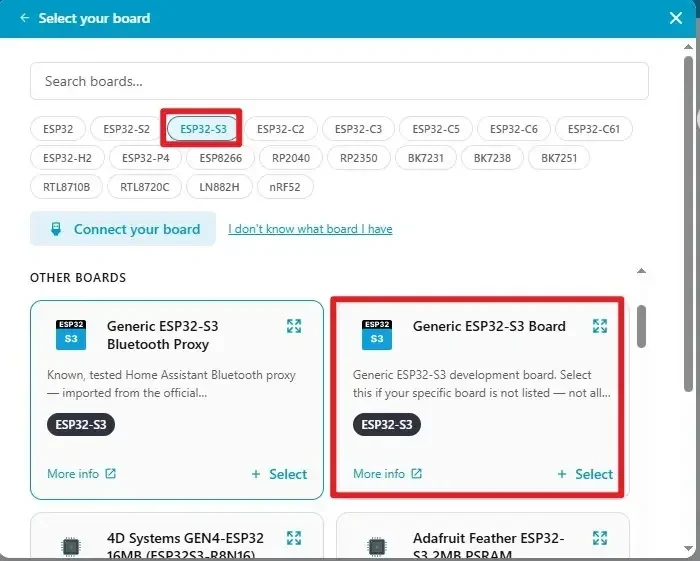
C. Name the project. Complete the new project task.

Step 03: Copy the official code into the project (the code is provided above).
However, ensure that the project name in the code matches the name of the project you just created.
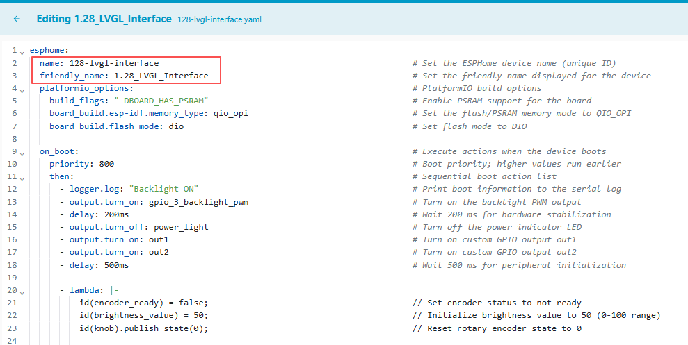
Step 04: Modify the WiFi.

Click the three dots in the top-right corner, then click secret.
You can enter your own WiFi name and password. (Ensure that this WiFi is on the same local network as your Home Assistant system)


Step 05: Click Install, select the USB installation method suitable for the current environment, choose the serial port corresponding to the CrowPanel, and complete compilation and flashing. After flashing finishes, open the log window; you should see the device boot and the POWER ON log.


Step 06: Wait for compilation.

Step 07: After compilation completes, click flash to upload.

Step 08: Select the connected serial port.

Step 09: Click to connect to the corresponding serial port (confirm the hardware is already connected).

Step 10: Wait for the download to complete.

5. Hardware Operation Steps
Step 01: With the device powered off, check that the screen, knob housing, and USB interface show no obvious damage, then use a USB cable that supports data transfer to connect the CrowPanel 1.28inch-HMI ESP32 Rotary Display to the computer.

Step 02: Wait for the LVGL page to be built and look straight at the center of the circular screen. The page should display the background image, the Brightness title, the brightness arc, and 50%. Rotate the knob clockwise and counterclockwise to confirm that the arc, percentage, and actual backlight change synchronously; the device should not freeze, restart, or stop refreshing for an extended period. This lesson's code does not configure touch functionality, so touch response is not treated as an acceptance item.

6. Key Code Explanation
6.1 Boot Initialization and Knob Protection
on_boot:
  priority: 800
  then:
    - output.turn_on: gpio_3_backlight_pwm
    - delay: 200ms
    - output.turn_off: power_light
    - output.turn_on: out1
    - output.turn_on: out2
    - delay: 500ms
    - lambda: |-
        id(encoder_ready) = false;
        id(brightness_value) = 50;
        id(knob).publish_state(0);
    - light.turn_on:
        id: back_light
        brightness: 0.5
    - lambda: |-
        lv_arc_set_value(id(arc_brightness), id(brightness_value));
        char buf[10];
        snprintf(buf, sizeof(buf), "%d%%", id(brightness_value));
        lv_label_set_text(id(lbl_brightness), buf);
        lv_refr_now(NULL);
    - delay: 200ms
    - lambda: |-
        id(encoder_ready) = true;
After the device boots, it first turns on the GPIO46 backlight and sets the on-board output states of GPIO40, GPIO1, and GPIO2. Once the display has stabilized, the program sets the brightness to 50%, resets the encoder count to 0, and temporarily disables knob event handling. It then initializes the 50% backlight, arc value, and percentage label simultaneously, and forces an LVGL refresh. The encoder is only enabled after a further 200 ms delay. This complete chain ensures that the actual backlight, arc, and text all use the same state value at startup, and it also prevents initialization events from being misidentified as rotation.
6.2 Image Resource Conversion
At compile time, ESPHome reads bj_light_128_1.png, scales it to 240×240, and converts it into RGB565 pixel data suitable for the LCD. The file path is relative to the directory containing the YAML, so a missing file or a name mismatch will cause an error directly at compile time. RGB565 uses 16 bits per pixel, balancing color quality against memory usage.
6.3 LVGL Buffer and Display Refresh
lvgl:
  displays:
    - round_display
  buffer_size: 50%

display:
  - platform: ili9xxx
    id: round_display
    model: GC9A01A
    cs_pin: GPIO9
    dc_pin: GPIO3
    reset_pin: GPIO14
    invert_colors: true
    show_test_card: false
    rotation: 0
    update_interval: 10ms
The GC9A01A uses GPIO9, GPIO3, and GPIO14 as the chip-select, data/command, and reset pins, with color inversion enabled, rotation set to 0, and the test card disabled. The display component updates every 10 ms. LVGL uses this display as the drawing target with a 50% buffer; the background image and arc depend on the 80 MHz Octal PSRAM. If a black screen appears, check the SPI and control pins; if restarts or memory allocation failures occur, check the PSRAM and build parameters.
6.4 Stacking Order of Background, Title, Arc, and Percentage
widgets:
  - image:
      align: CENTER
      id: img_bg
      src: img_bg_light
      width: 240
      height: 240
      antialias: true
  - label:
      align: CENTER
      id: lbl_title
      y: -40
      text_font: montserrat_12
      text: "Brightness"
      text_color: 0xFFFFFF
      text_opa: "100%"
  - arc:
      align: CENTER
      id: arc_brightness
      value: 50
      min_value: 0
      max_value: 100
      start_angle: 135
      end_angle: 45
      width: 160
      height: 160
      arc_color: 0x1A1A1A
      arc_width: 12
      arc_rounded: true
      indicator:
        arc_color: 0x00D2FF
        arc_width: 12
        arc_rounded: true
      knob:
        bg_color: 0xFFFFFF
        bg_opa: "100%"
        width: 20
        height: 20
        radius: 10
  - label:
      align: CENTER
      id: lbl_brightness
      text_font: montserrat_36
      text: "50%"
      text_color: 0xFFFFFF
      text_opa: "100%"
The continuous and complete definitions of the interface widgets are preserved here. The background image is drawn first, centered at 240×240 with antialiasing enabled; the title then offsets upward by 40 px, using a 12 px Montserrat white font. The arc ranges from 0 to 100, with an initial value of 50, drawn from 135° to 45°; the background track is dark gray and the progress indicator is sky blue, both 12 px wide, with a white circular knob. Finally, the 36 px white percentage label is drawn.
LVGL creates widgets from bottom to top in definition order, so the background image must come first, with the text and arc following. arc_brightness and lbl_brightness are the object IDs used by the boot and knob Lambdas; if you change only the IDs in the YAML without synchronously modifying the Lambdas, the compilation will fail or the interface will not update.
6.5 Knob Input and 5% Stepping
sensor:
  - platform: rotary_encoder
    id: knob
    name: "Encoder"
    pin_a:
      number: 45
      mode:
        input: true
        pullup: true
    pin_b:
      number: 42
      mode:
        input: true
        pullup: true
    resolution: 1
    filters:
      - debounce: 20ms
      - lambda: return round(x);
GPIO45 and GPIO42 read the knob A/B phase signals, with internal pull-ups stabilizing the default levels, and 20 ms debouncing is used to filter mechanical contact jitter. The event handler compares the current count with the previous count: a negative difference decreases brightness by 5, a positive difference increases brightness by 5, and the result is clamped to 0–100. The first event only establishes the count baseline and does not change the brightness.
6.6 Complete Knob Event, PWM, and Interface Synchronization
    on_value:
      then:
        - lambda: |-
            if (!id(encoder_ready)) return;
            static bool first_run = true;
            static int last_encoder = 0;
            int current = (int) id(knob).
state;

            if (first_run) {
              last_encoder = current;
              first_run = false;
              return;
            }

            int delta = current - last_encoder;
            last_encoder = current;
            if (delta == 0) return;

            if (delta < 0) {
              id(brightness_value) -= 5;
            } else {
              id(brightness_value) += 5;
            }

            if (id(brightness_value) < 0) id(brightness_value) = 0;
            if (id(brightness_value) > 100) id(brightness_value) = 100;

            float level = id(brightness_value) / 100.
0f;
            id(gpio_3_backlight_pwm).set_level(level);

            lv_arc_set_value(id(arc_brightness), id(brightness_value));
            char buf[10];
            snprintf(buf, sizeof(buf), "%d%%", id(brightness_value));
            lv_label_set_text(id(lbl_brightness), buf);
            lv_refr_now(NULL);
The callback first checks the startup protection flag. The first valid event only stores the current encoder value as the baseline; afterward, it determines direction from the difference between the current value and the previous value. Each valid step changes the value by 5% and then clamps the range to 0–100. Dividing the brightness by 100.0f yields a PWM level of 0.0–1.0, which is written to GPIO46; the same integer is then written to the arc and the percentage label, and finally a forced refresh is performed.
This continuous block of code illustrates the most important data flow in this lesson: knob.state → delta → brightness_value → GPIO46 PWM, arc_brightness, lbl_brightness. All three outputs depend on the same state, so under normal conditions they will not drift out of sync with one another. If the text and arc change but the backlight does not, check the LEDC output; if the backlight changes but the interface does not, check the LVGL object IDs and the refresh call.
7. Experimental Observations
After the device resets, power and backlight turn on first, followed by the background image, title, brightness arc, and the 50% percentage. The interface should fully cover the round screen, with no obvious rectangular clipping, color corruption, or missing sections.
When the knob is rotated, the percentage changes in 5% steps, the indicator length of the brightness arc changes in sync, and the actual backlight brightens or dims accordingly. After reaching 0% and 100%, continued rotation keeps the value within the valid range.
When rotating clockwise and counterclockwise, the arc, percentage, and actual backlight should change synchronously; the first knob event only establishes the counting baseline and may not change the brightness immediately. During continuous fast and slow rotation, the device should not restart, freeze, or stop refreshing for an extended period. Since this lesson's YAML does not configure a touch component, touching the screen will not trigger any interface or brightness change.

8. Function or Resource Creation Process
This lesson uses a background PNG that has already been created, and does not require learners to redraw it. The resource integration workflow is: place bj_light_128_1.png in the same directory as the YAML, then ESPHome scales it to 240×240 and converts it to RGB565 at compile time. The img_bg_light in the code is the compiled resource ID, while img_bg is the runtime LVGL image widget ID; the two serve different purposes.
If you later replace the background image with a custom one, keep it at 240×240 pixels and account for the fact that the four corners of the round screen are not visible. After replacing the file, re-run Validate and compile to confirm that the image format, memory usage, and control text contrast are all normal.
9. Code Download
-
Official code: Elecrow ESPHome Lesson_Code
-
Official materials: