Lesson 05: Control the LVGL Interface by Touch
1. Results Showcase
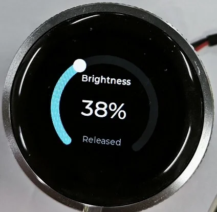
In this lesson, we add capacitive-touch control to the brightness interface created in the previous lesson. After flashing the program, you can drag the circular slider directly on the screen to change the display brightness. The center percentage value updates in real time, and the rotary encoder remains available as a second control method.
The text at the bottom of the screen reports the current touch coordinates while the screen is pressed and displays Released when the finger leaves the screen.
2. Project Introduction
The CrowPanel 1.28inch-HMI ESP32 Rotary Display integrates a 240 × 240 GC9A01A round LCD, a CST816 capacitive-touch controller, and a rotary encoder. In this project, ESPHome reads the touch controller through I²C and passes the coordinates to LVGL. LVGL then handles the touch event on the adjustable arc and updates the PWM backlight output.
The interface supports two input paths:
- Touch: Drag the LVGL arc knob to select a brightness value from 0% to 100%.
- Rotary encoder: Rotate the knob to increase or decrease brightness in 5% steps.
Both paths update the same brightness_value, PWM output, arc, and percentage label, so the visual state always matches the actual backlight level.
3. Preparation
Before starting, make sure you have completed the previous ESPHome lessons and prepared the following:
- CrowPanel 1.28inch-HMI ESP32 Rotary Display
- USB data cable
- Home Assistant with the ESPHome Device Builder add-on
- A computer and the Home Assistant server on the same local network
- A 2.4 GHz Wi-Fi network
Code download link:
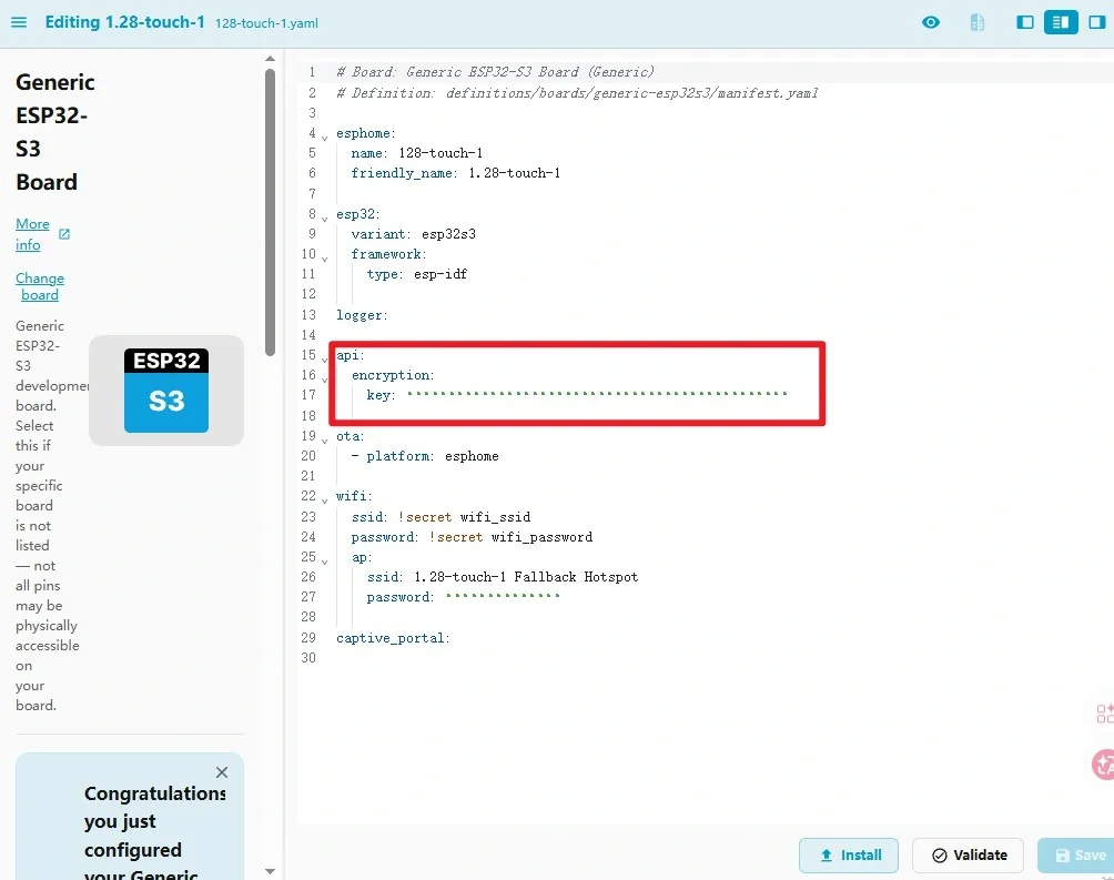
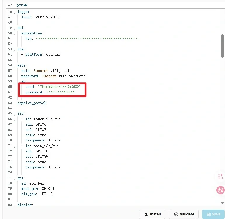
Keep the API encryption key generated for your own device. Do not copy the example key into another project. Wi-Fi credentials can be stored in ESPHome
secrets.yamlaswifi_ssidandwifi_password.
4. Code Explanation
4.1 Basic Configuration and Startup Initialization
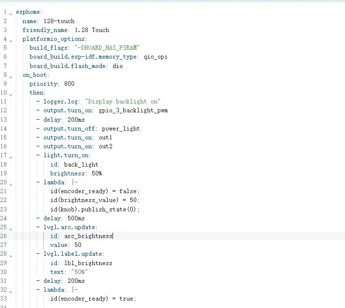
The esphome section defines the node name, PSRAM-related PlatformIO options, and the startup sequence. At boot, the program enables the display power and backlight, initializes brightness to 50%, resets the encoder state, and updates the LVGL arc and label. The short initialization lock prevents an encoder event from changing the value before the interface is ready.
4.2 ESP32, Logging, API, and OTA
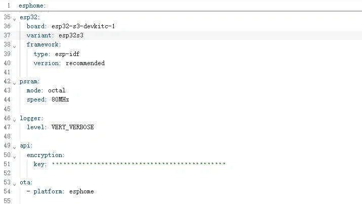
Select esp32-s3-devkitc-1, use the ESP-IDF framework, and enable octal PSRAM at 80 MHz. Logging is set to VERY_VERBOSE in this example so touch coordinates and state changes can be observed during debugging. The native API connects the device to Home Assistant, while OTA enables later wireless updates.
4.3 Wi-Fi, I²C, and SPI
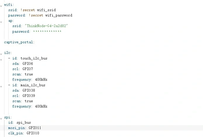
Two independent I²C buses are configured. The CST816 touch controller uses GPIO6 for SDA and GPIO7 for SCL at 400 kHz. A second I²C bus on GPIO38 and GPIO39 is reserved for other onboard peripherals. The LCD uses SPI with GPIO11 as MOSI and GPIO10 as the clock.
4.4 LCD Display Configuration
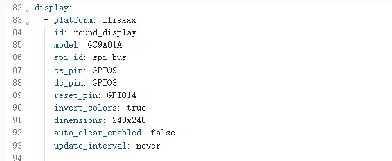
The display uses the ili9xxx component with the GC9A01A model. Its resolution is 240 × 240. auto_clear_enabled: false and update_interval: never allow LVGL to manage screen rendering instead of the display component refreshing independently.
4.5 CST816 Touchscreen Configuration
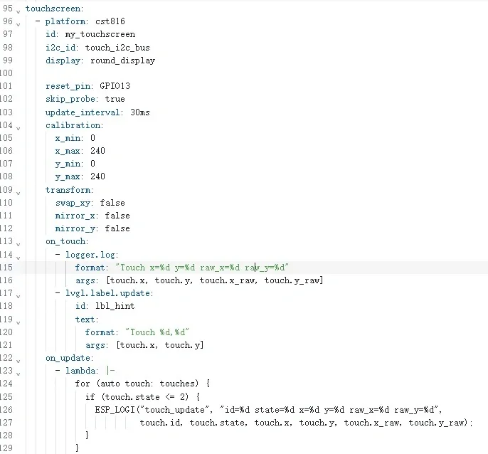
The touchscreen component connects the CST816 controller to the display and maps its raw coordinates to the 240 × 240 screen. The reset pin is GPIO13 and touch data is sampled every 30 ms.
Three event handlers make testing easier:
on_touchlogs the coordinates and showsTouch x,yinlbl_hint.on_updatelogs the ID, state, screen coordinates, and raw coordinates for every active touch.on_releaselogs the release and changes the hint label toReleased.
If touch movement is reversed or rotated on a different hardware revision, adjust swap_xy, mirror_x, and mirror_y in the transform section.
4.6 Global Variables and Outputs
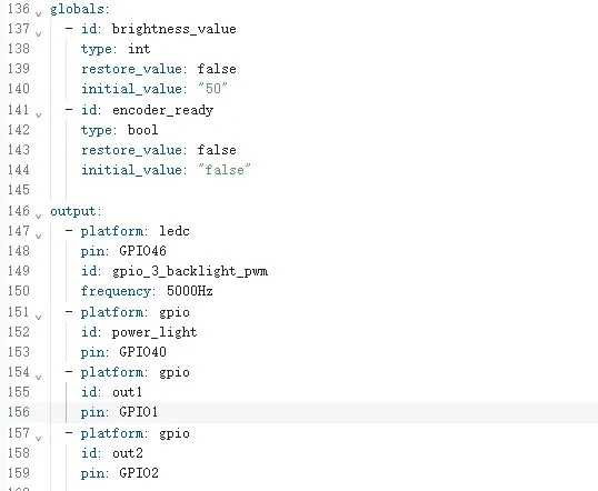
brightness_value stores the current percentage, while encoder_ready prevents unwanted encoder processing during startup. The LEDC output on GPIO46 generates a 5 kHz PWM signal for the backlight. GPIO40, GPIO1, and GPIO2 control the other display power lines required by the board.
4.7 Backlight and Rotary Encoder
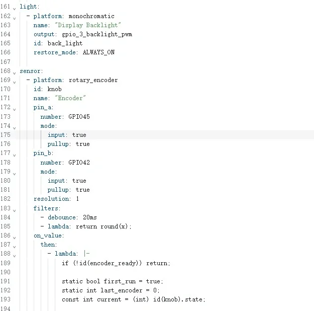
The monochromatic light component exposes the PWM backlight to ESPHome. The rotary encoder uses GPIO45 and GPIO42 with pull-ups and debounce filtering. Each valid encoder step changes brightness by 5%, clamps the result to 0–100%, updates the PWM duty cycle, and synchronizes the LVGL arc and label.
4.8 Full-Screen Touch Sensor and Fonts
The touchscreen binary sensor covers the complete 240 × 240 coordinate range. It provides a simple pressed/released entity in Home Assistant and writes both events to the log. Three Montserrat font sizes are loaded for the title, hint, and central brightness value.
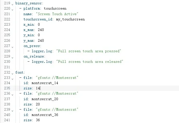
4.9 LVGL Interface and Touch Interaction
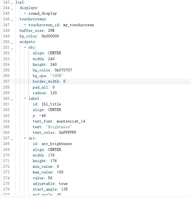
LVGL is linked to both round_display and my_touchscreen. The interface contains a circular background, title, adjustable arc, central percentage label, and touch-status label.
The key setting is adjustable: true on arc_brightness. It allows LVGL to move the arc knob from touch input. Every on_value event reads the arc value, limits it to 0–100%, writes the corresponding PWM level, and refreshes the percentage text. Because the encoder also updates this same arc, touch and rotation remain synchronized.
5. Flashing Steps
5.1 Create an ESPHome Device
Open Home Assistant and go to the ESPHome Device Builder page.
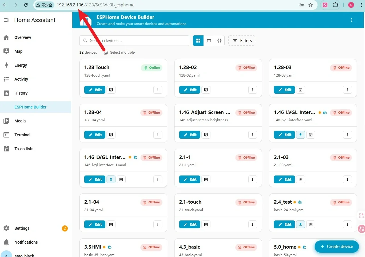
Click + NEW DEVICE.
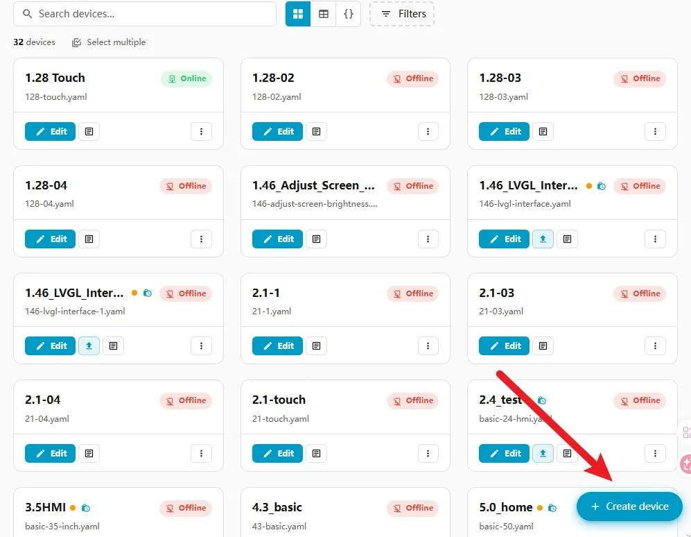
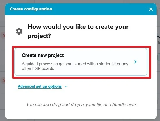
Select the option to create a new project and continue through the setup wizard.
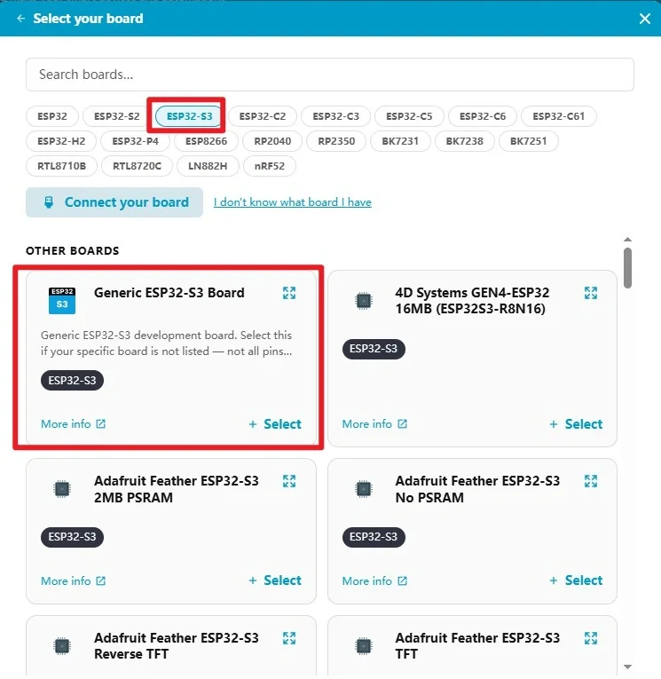
Choose ESP32-S3 as the device type. If the wizard requests a specific board, you may select a compatible ESP32-S3 option because the generated configuration will be replaced in the next step.
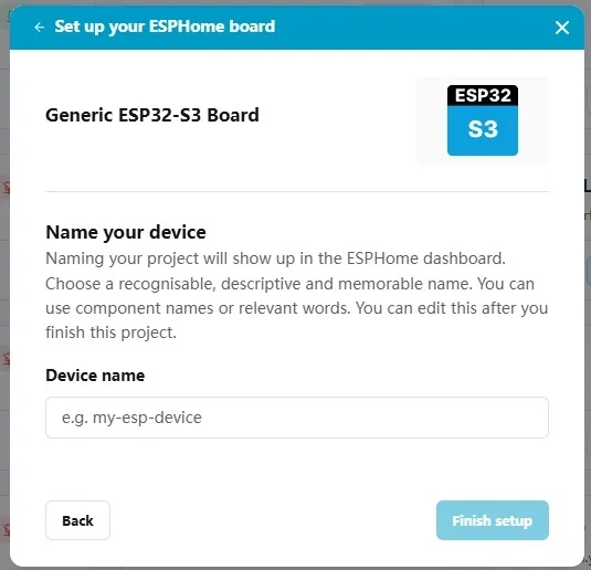
Enter a project name such as 128-touch. Use lowercase letters, numbers, and hyphens; avoid spaces and special characters.
After generation, keep the device-specific API encryption key. Open the device configuration editor and replace the remaining generated content with the configuration from Lesson05/128-touch.yaml, while preserving your own key.
Configure your own Wi-Fi credentials. The computer, Home Assistant server, and CrowPanel must be connected to the same local network.
5.2 Compile the Firmware
Save the configuration, click INSTALL, and choose the USB/manual installation option for the first flash.
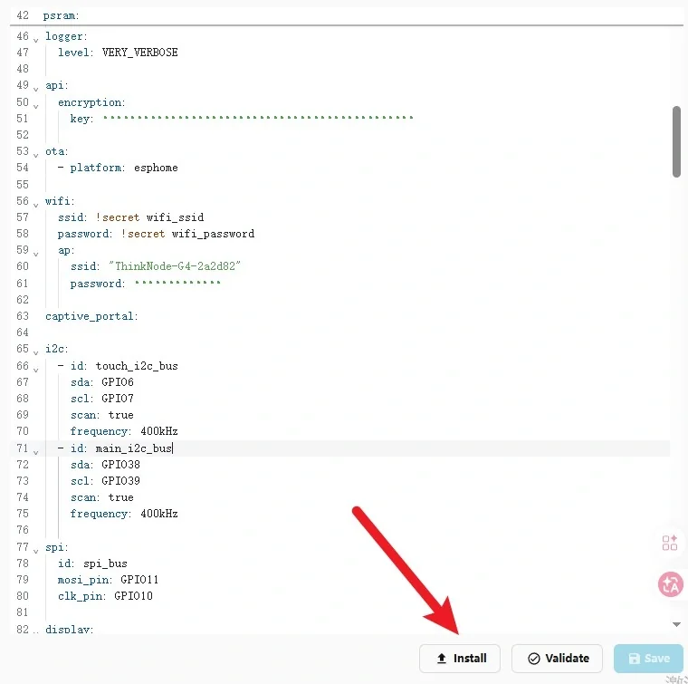
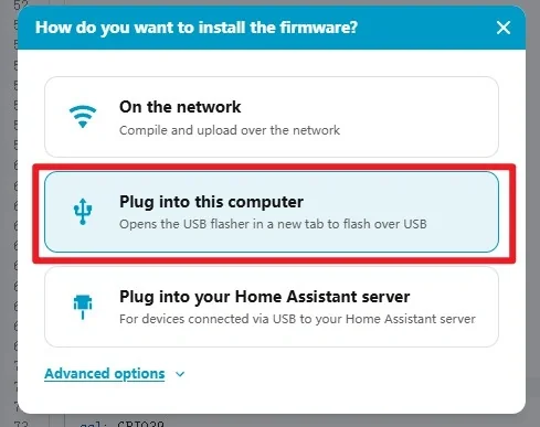
ESPHome validates the YAML and compiles the firmware. The first build can take several minutes because the required components and fonts must be downloaded and compiled.
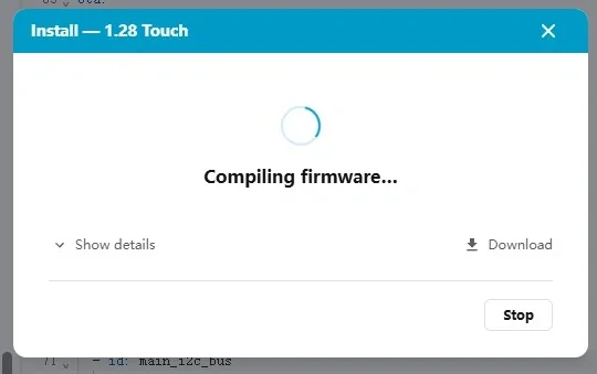
5.3 Flash Through the Browser
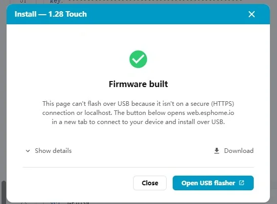
Connect the CrowPanel to the computer with a USB data cable. When compilation finishes, click Open USB Flasher. A Chromium-based browser such as Chrome or Edge is required for Web Serial.
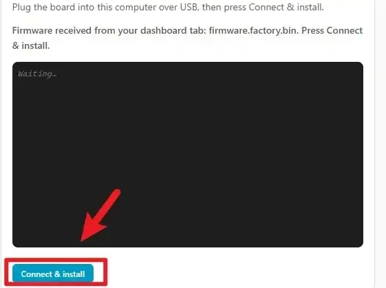
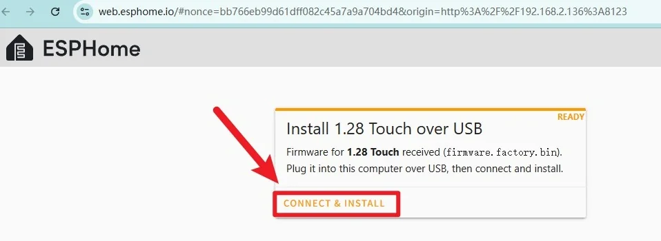
Click CONNECT & INSTALL.
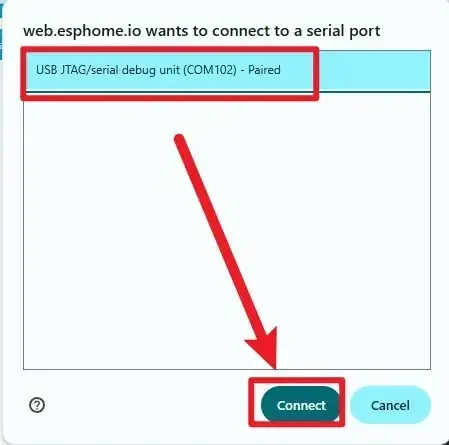
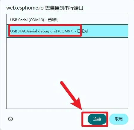
Select the serial port corresponding to the ESP32-S3 and click Connect. If no port appears, check that the cable supports data transfer and install the required USB serial driver.
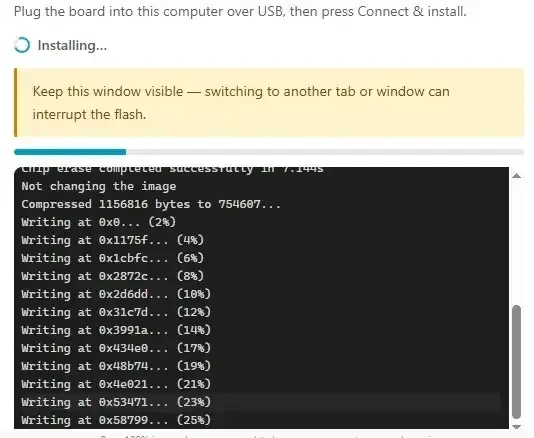
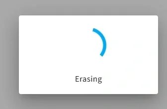
Wait for the download to complete.
6. Result Verification
After startup, ESPHome connects to the configured Wi-Fi network. Return to the ESPHome dashboard and confirm that the device status changes to ONLINE.
The display initially shows 50%. Drag the white knob on the blue arc and verify that:
- The percentage changes continuously with your finger.
- The physical screen brightness follows the displayed percentage.
- The bottom label shows touch coordinates and then
Released. - Rotating the encoder still adjusts the same value in 5% steps.
Once the device is online, later configuration changes can be installed wirelessly by selecting the online installation option in ESPHome.
7. Troubleshooting
- The screen works but touch does not: Check the CST816 I²C pins (SDA GPIO6, SCL GPIO7), GPIO13 reset pin, and
i2c_id: touch_i2c_bus. - Touch coordinates move in the wrong direction: Change the
transformoptions undertouchscreenand testswap_xy,mirror_x, ormirror_y. - The arc responds but brightness does not change: Confirm the LEDC backlight output is GPIO46 and the light/output IDs match the YAML.
- Compilation fails while loading fonts: Make sure ESPHome has internet access so it can retrieve the Google Fonts resource.
- The device stays offline: Verify the 2.4 GHz Wi-Fi credentials and ensure the device and Home Assistant are on the same LAN.
- No serial port is listed: Use a USB data cable, try another USB port, and put the ESP32-S3 into download mode if required.
You have now completed touch interaction for the LVGL brightness interface. The same touchscreen events can be reused in later projects to create buttons, sliders, menus, and other interactive controls.