2.4_2.8inch_Lesson04_SD_Card_Image_Slideshow
1. Course Introduction
This lesson uses the onboard SD card slot of the CrowPanel Advance 2.4inch ESP32-S3 HMI to read BMP images and display them in a loop on the LCD screen. After the experiment completes, the screen first shows the SD card initialization result; once initialization succeeds, it displays 1.bmp through 5.bmp from the SD card root directory in sequence, with each image staying on screen for about 5 seconds.
The focus of this lesson is not downloading images over the network, but having the development board read image files from a local SD card. This can be used for product splash screens, offline photo albums, menu backgrounds, sensor data display page backgrounds, and similar scenarios.
2. Learning Objectives
- Be able to prepare the SD card, card reader, BMP image assets, and the Arduino project.
- Be able to process ordinary images into the
320 x 240resolution required by the 2.4inch / 2.8inch screen. - Be able to save images as 24-bit BMP format.
- Be able to place
1.bmpthrough5.bmpinto the SD card root directory. - Be able to modify the image path, display dimensions, and slideshow dwell time in the Arduino code.
- Be able to understand the LCD status prompts, SD card initialization, directory scanning, and line-by-line BMP display flow in the upgraded code.
- Be able to determine, based on the LCD prompts and serial logs, whether the SD card mount, file reading, and image display are working correctly.
3. Preparations
3.1 Hardware and Accessories
- 1 x CrowPanel Advance 2.4inch ESP32-S3 HMI development board.
- 1 x USB Type-C data cable that supports data transfer, used for power, program flashing, and viewing serial logs.
- 1 x Micro SD / TF card, used to store BMP images.
- 1 x USB card reader, used to copy images to the SD card from a computer.
- 1 x Computer, used to process images, copy files, and flash the Arduino program.
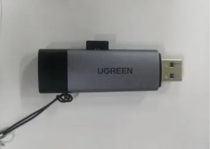
Note: It is recommended to format the SD card as FAT32 first. If your computer cannot reliably recognize the SD card, the development board will likely also fail to mount it.
3.2 Software and Files
- Arduino IDE.
- The ESP32 Arduino development environment configured per Lesson 01.
- The Arduino library files for this course series imported per Lesson 01.
- Windows Paint, or any other image-processing tool that can adjust pixel dimensions and export 24-bit BMP.
- This lesson's Arduino project:
- This lesson's sample image assets:
Note: This tutorial targets 2.4inch Version 1.0 / 1.1 / 1.2, and also applies to the 2.8inch project at the same resolution. Both the 2.4inch and 2.8inch displays have a resolution of 320 x 240, so the BMP image dimensions and the width/height parameters in the code can remain consistent; the main differences are the physical dimensions, the bundled library files, and the official code version paths. Before flashing, you must still confirm that the library files match the screen size.
Code and Resource Download
Code download: - SD_CrowPanel_ESP32_Advance_HMI_2.4_2.8
Resource download: - 5 BMP image assets total link
4. SD Card Processing and BMP Image Processing
4.1 Overall Processing Sequence
- Prepare the images you want to display, or use the course-provided
320_240sample images directly. - Use an image tool to resize the images to
320 x 240. - Save the images as 24-bit BMP format.
- Name the images
1.bmp,2.bmp,3.bmp,4.bmp,5.bmp. - Use a card reader to copy the BMP images to the SD card root directory.
- Safely eject the SD card, then insert it into the SD card slot of the CrowPanel Advance HMI.
- Open the Arduino project and confirm the image path, display dimensions, and slideshow dwell time in the code.
- Compile and flash the program, then observe the SD card status prompt on the LCD and the image slideshow effect.
4.2 Image Preparation
Choose an image you want to display on the screen. You may use an image you downloaded yourself, or use the sample assets provided in this course directly. You can save the image to the desktop or another easy-to-find location first.
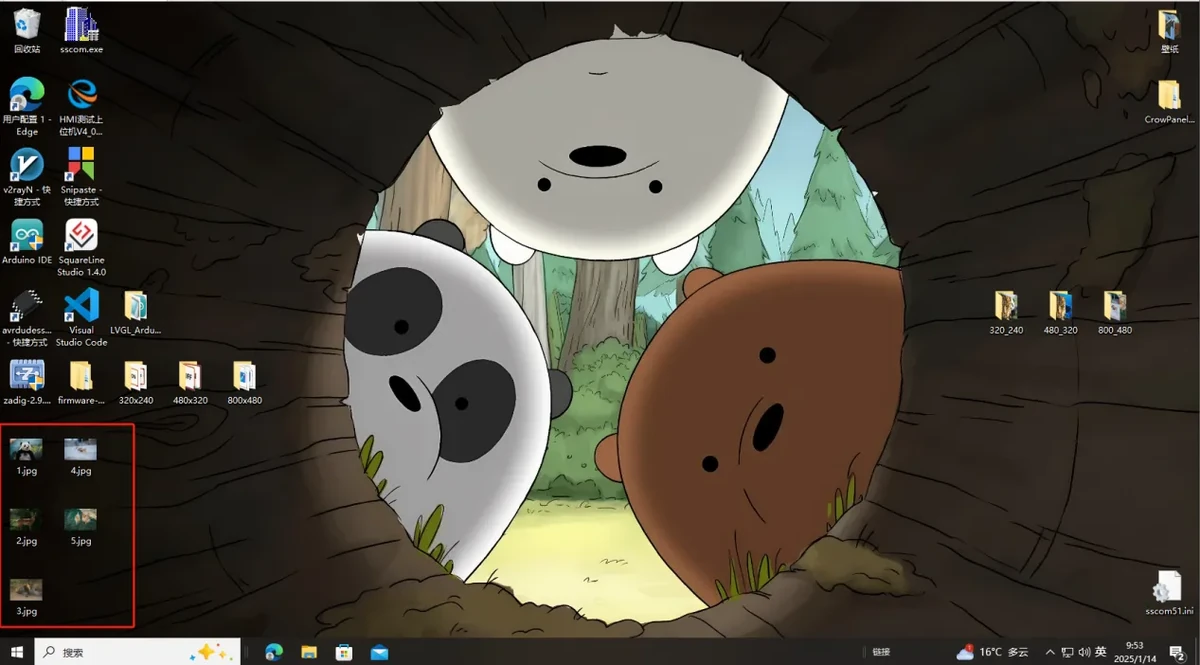
The official tutorial provides image resolutions corresponding to different screen sizes. The 2.4inch / 2.8inch screen used in this course has a resolution of 320 x 240.
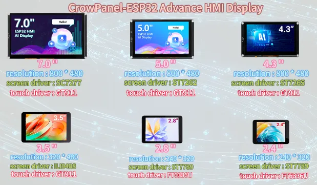
Note: For 2.4inch / 2.8inch, use 320 x 240. The actual image dimensions, the displayImage(..., 320, 240) parameters in the code, and the screen orientation must all stay consistent; otherwise you are likely to see a garbled display, misalignment, or only part of the image showing.
4.3 Open the Image Processing Tool
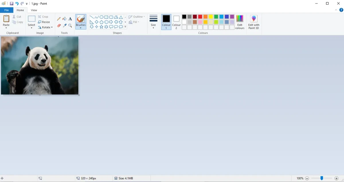
Open the "Paint" tool in Windows.
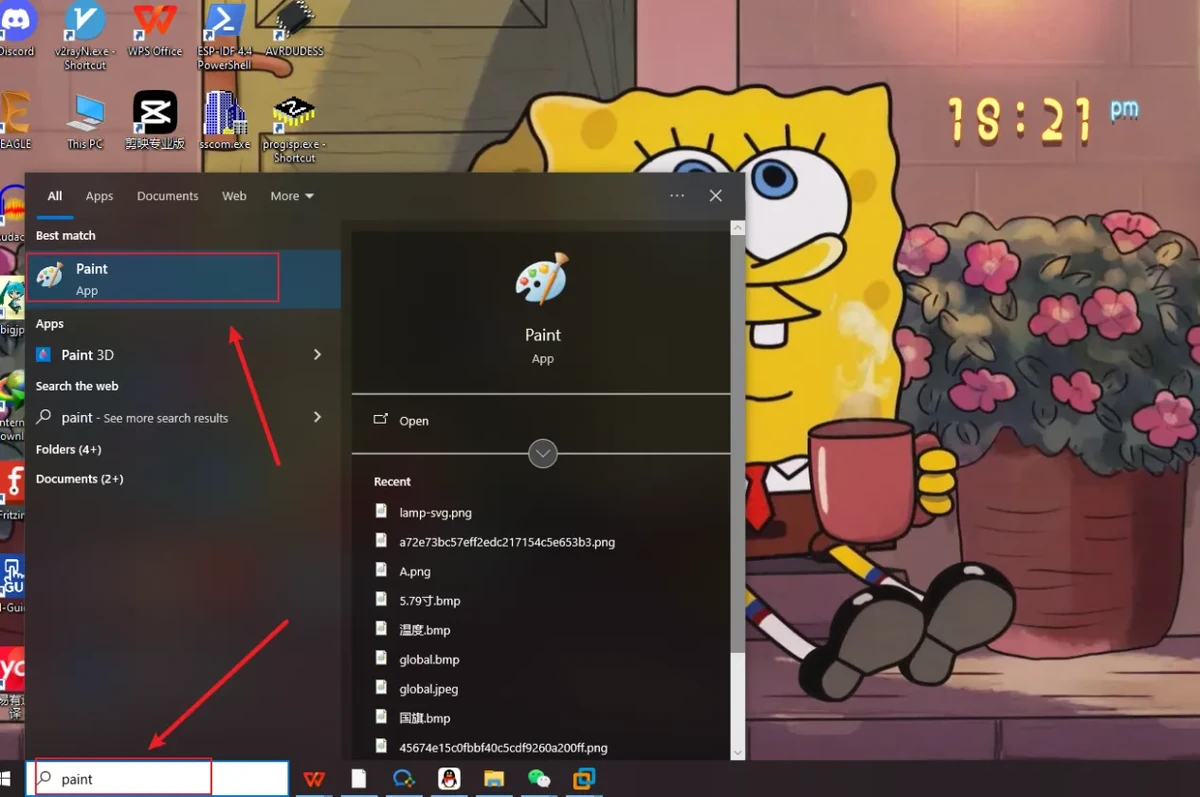
Drag the prepared image into Paint, or use Paint's Open function to select the image file.
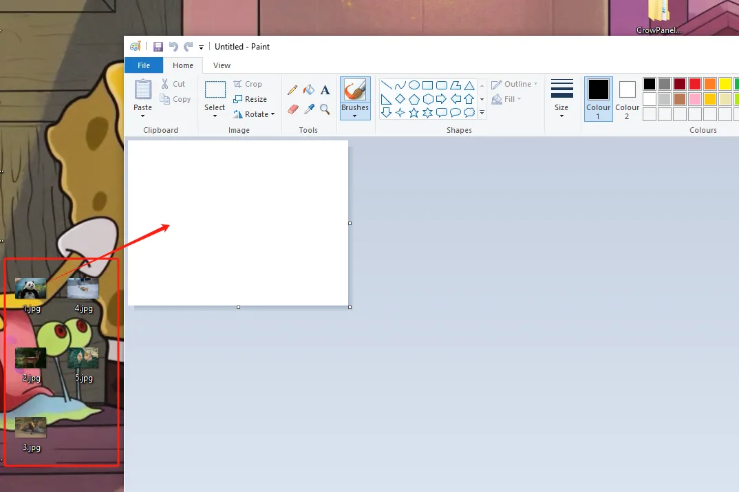
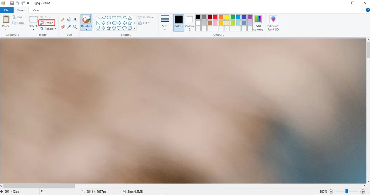
4.4 Adjust the Image Pixel Dimensions
Click the Resize function in Paint, switch the unit to pixels, then set the horizontal and vertical dimensions to:
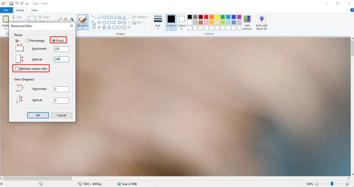
Click OK to finish resizing the image.
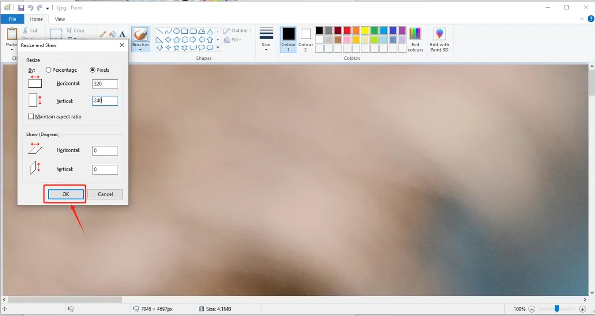
After resizing, check whether the image proportions and content look as expected.
4.5 Save as 24-bit BMP
Choose Save As and save the processed image to a location on your computer that is easy to find.
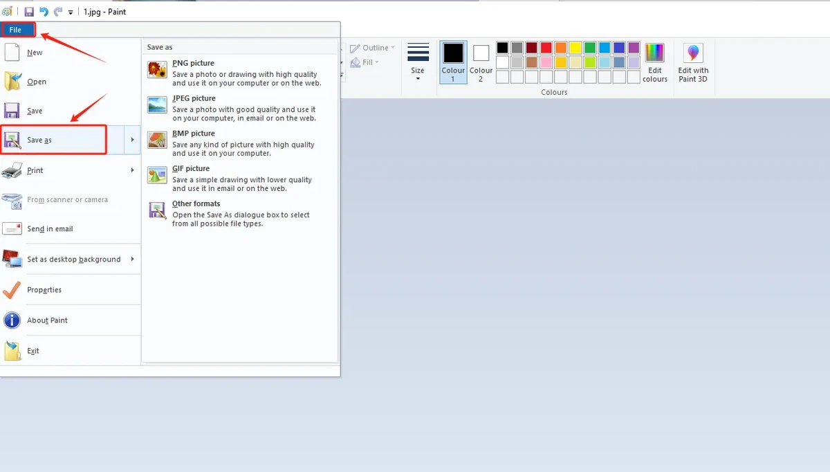
Select BMP as the save format, and make sure the image depth is 24-bit. It is recommended to name the files 1.bmp, 2.bmp, 3.bmp, 4.bmp, 5.bmp according to the default code path.
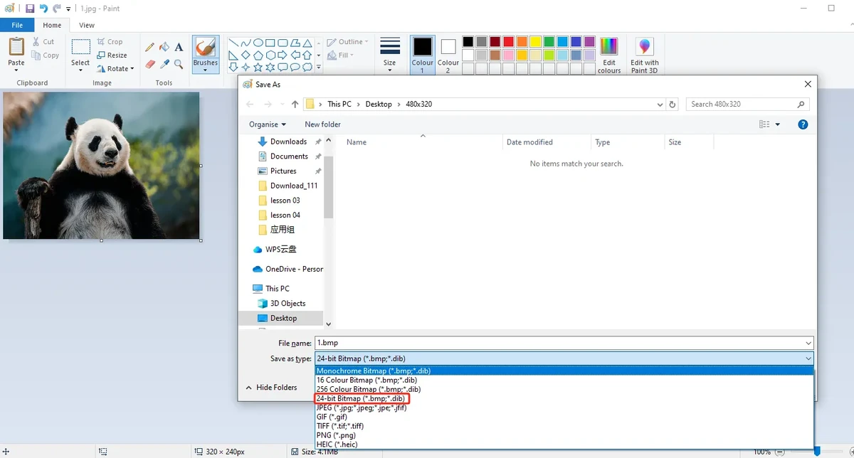
Note: Do not just change the file extension. You must use an image tool to Save As BMP and confirm that it is a 24-bit image depth.
4.6 Copy Images to the SD Card
Insert the Micro SD / TF card into the card reader, then connect the card reader to your computer.
Open the SD card drive and copy the processed 1.bmp through 5.bmp to the SD card root directory.
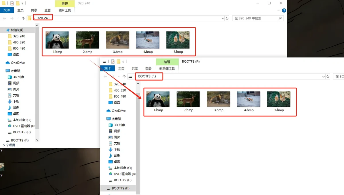
The recommended SD card root directory structure is as follows:
After copying is complete, safely eject the SD card and remove it from the card reader, then insert it into the SD card slot of the CrowPanel Advance HMI 2.4inch.
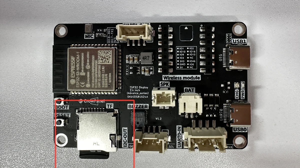
Note: The default code for this lesson reads the SD card root directory paths /1.bmp through /5.bmp, so do not put the images into subfolders. The file names must match the code exactly; it is recommended to use English and numbers for naming, and avoid Chinese characters, spaces, and special symbols.
5. Software Operation Steps
5.1 Open the Arduino Project
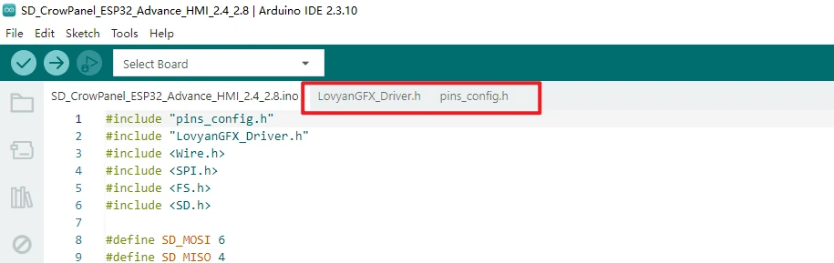
Open this lesson's project file using the Arduino IDE:
After opening, first confirm that project files such as pins_config.h and LovyanGFX_Driver.h are in the same project directory, to avoid compilation errors caused by missing header files when only a single .ino file is opened.
5.2 Configure the Development Board Parameters
In the Arduino IDE Tools menu, confirm the following parameters:
Board: ESP32S3 Dev Module
Port: Select the serial port corresponding to the current board
Flash Size: 16MB (128Mb)
PSRAM: OPI PSRAM
Partition Scheme: Huge APP (3MB No OTA/1MB SPIFFS)
Serial Monitor baud: 115200
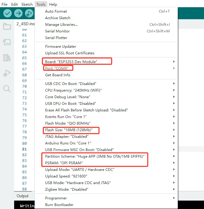
Note: Before flashing, confirm that you are using the library files corresponding to 2.4inch / 2.8inch. If compilation fails, first check whether the ESP32 Arduino Core version 3.3.8 and the course library files are consistent with Lesson 01.
5.3 Compile and Upload the Program
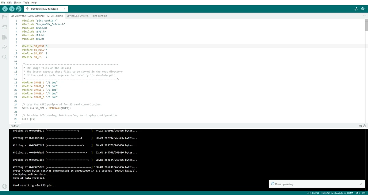
Click the Upload button in the top-left corner of the Arduino IDE and wait for compilation and flashing to complete.
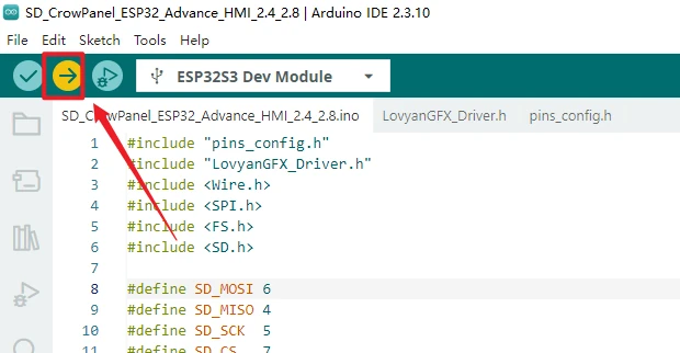
If the upload gets stuck at Connecting..., refer to the download troubleshooting steps in Lesson 01: check whether the port is occupied by the Serial Monitor, and if necessary, use BOOT / RESET per the board requirements to enter download mode.
5.4 Open the Serial Monitor to View Logs
After flashing completes, open the Serial Monitor and select baud rate 115200. When the program starts, it prints the SD card mount result, the SD card capacity, and the root directory file list.
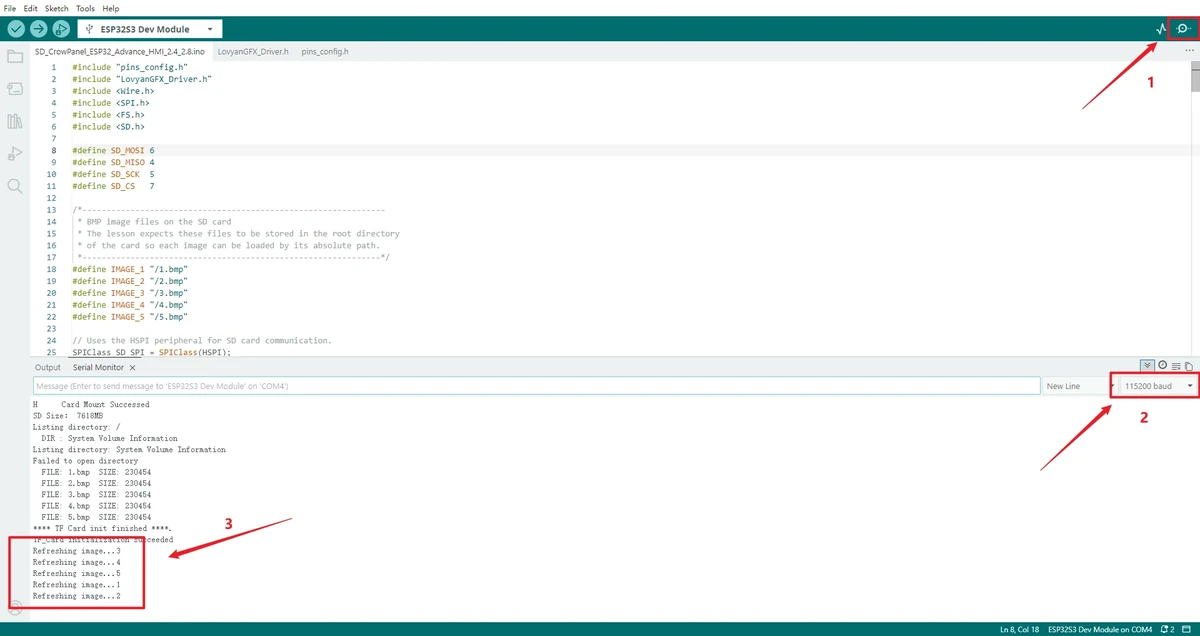
If you see Card Mount Successed, SD Size, Listing directory: /, and the file list of 1.bmp through 5.bmp in the serial output, it means the SD card mount and file preparation are basically normal. At this point the LCD will first show SD_Card OK, then enter the image slideshow.
6. Hardware Operation Steps
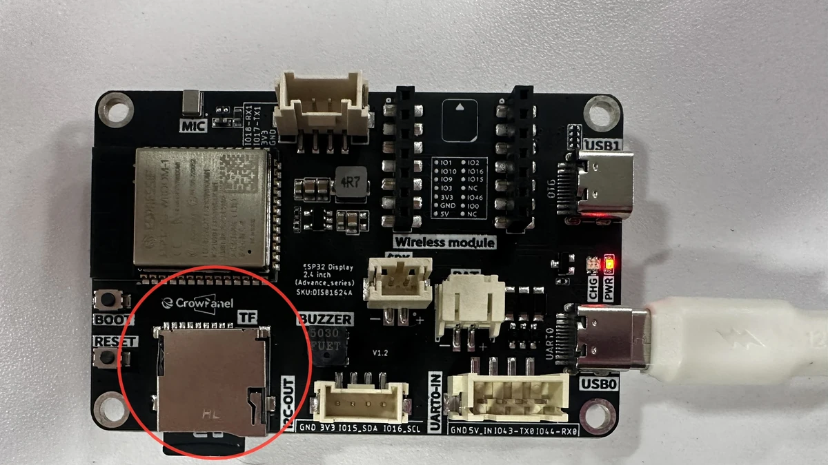
With the board powered off or not yet running, insert the prepared TF card into the 2.4 inch development board card slot. Connect the development board to the computer using a USB cable, and wait for the board to reset after the upload completes.
7. Key Code Explanation
7.1 Header Files, SD Pins, and Global Objects
#include "pins_config.h"
#include "LovyanGFX_Driver.h"
#include <Wire.h>
#include <SPI.h>
#include <FS.h>
#include <SD.h>

#define SD_MOSI 6
#define SD_MISO 4
#define SD_SCK  5
#define SD_CS   7

SPIClass SD_SPI = SPIClass(HSPI);
LGFX gfx;
The upgraded code consolidates the display driver, SPI, file system, and SD card libraries at the top of the file. SD_MOSI, SD_MISO, SD_SCK, and SD_CS correspond to the SPI pins used by the onboard SD card slot; SD_SPI = SPIClass(HSPI) indicates that SD card communication uses the ESP32-S3's HSPI bus. LGFX gfx is the screen drawing object, and all subsequent screen clearing, text prompts, and image pushing are done through it.
7.2 LCD Status Prompt Function show_test()
void show_test(int lcd_w, int lcd_h, int x, int y, const char * text)
{
  gfx.fillScreen(TFT_BLACK);
  gfx.setTextSize(2);
  gfx.setTextColor(TFT_RED);
  gfx.setCursor(x, y);
  gfx.print(text);
}
This is a change in the upgraded code that makes it more suitable for teaching demonstrations. The program not only outputs the SD card status to the serial port, but also displays SD_Card OK or SD_Card Failed directly on the LCD. This way, even without opening the Serial Monitor, you can tell from the screen whether the SD card initialized successfully.
lcd_w and lcd_h are not currently used in any calculation; they are mainly kept for future layout extensions. The actual text position is controlled by x and y.
7.3 Initialization Flow setup()
void setup()
{
  Serial.begin(115200);

  gfx.init();
  gfx.initDMA();
  gfx.startWrite();
  gfx.fillScreen(TFT_BLACK);
  delay(500);

  pinMode(38, OUTPUT);
  digitalWrite(38, HIGH);

  if (SD_init() == 0)
  {
    Serial.println("TF_Card initialization succeeded");
    show_test(LCD_H_RES, LCD_V_RES, 75, 100, "SD_Card OK");
    delay(3000);
  } else {
    Serial.println("TF card initialization failed");
    show_test(LCD_H_RES, LCD_V_RES, 75, 100, "SD_Card Failed");
    delay(3000);
  }
  gfx.setRotation(2);
  gfx.fillScreen(TFT_BLACK);
  Serial.println( "----- Setup done -----" );
}
setup() is the first block executed after the board is powered on. The upgraded sequence is clearer: start the serial port first, then initialize the LCD and DMA, then turn on the backlight, then initialize the SD card. SD_init() returns 0 for success and 1 for failure, so here if (SD_init() == 0) is used to decide whether the screen shows SD_Card OK or SD_Card Failed.
The final gfx.setRotation(2) sets the screen orientation, and gfx.fillScreen(TFT_BLACK) clears the status prompt before entering the image slideshow.
7.4 Image Slideshow Logic loop()
void loop()
{
  Serial.println("Refreshing image...1");
  displayImage(SD, IMAGE_1, 320, 240);
  delay(5000);

  Serial.println("Refreshing image...2");
  displayImage(SD, IMAGE_2, 320, 240);
  delay(5000);

  Serial.println("Refreshing image...3");
  displayImage(SD, IMAGE_3, 320, 240);
  delay(5000);

  Serial.println("Refreshing image...4");
  displayImage(SD, IMAGE_4, 320, 240);
  delay(5000);

  Serial.println("Refreshing image...5");
  displayImage(SD, IMAGE_5, 320, 240);
  delay(5000);
}
loop() repeats continuously, so these 5 images keep playing in a slideshow. Before displaying each image, the serial port prints Refreshing image... followed by the index, making it easy to tell which image the program is currently trying to read. If a particular image fails to display, you can use the serial index to go back to the SD card and check the corresponding file.
7.5 SD Card Initialization SD_init()
int SD_init()
{
  SD_SPI.begin(SD_SCK, SD_MISO, SD_MOSI);
  if (!SD.begin(SD_CS, SD_SPI, 80000000))
  {
    Serial.println(F("ERROR: File system mount failed!"));
    SD_SPI.end();
    return 1;
  }
  else
  {
    Serial.println("Card Mount Successed");
    Serial.printf("SD Size: %lluMB \n", SD.cardSize() / (1024 * 1024));
  }
  listDir(SD, "/", 2);
  Serial.println("**** TF Card init finished ****.");
  return 0;
}
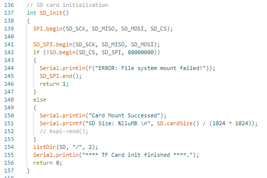
SD_init() handles SD card mounting and basic checks. SD_SPI.begin() first starts the SPI bus according to the pins of the onboard SD card slot, then SD.begin() uses the CS pin and the SPI bus to mount the file system. On mount failure, the code prints an error, shuts down the SD SPI, and returns 1; on successful mount, it prints Card Mount Successed and the SD card capacity.
It also calls listDir(SD, "/", 2) to scan the SD card root directory. This lets you confirm, before entering image display, whether 1.bmp through 5.bmp are actually present on the SD card.
7.6 Directory Scanning listDir()
void listDir(fs::FS & fs, const char *dirname, uint8_t levels) {
    Serial.printf("Listing directory: %s\n", dirname);
    File root = fs.open(dirname);
    if (!root) {
        Serial.println("Failed to open directory");
        return;
    }
    if (!root.isDirectory()) {
        Serial.println("Not a directory");
        return;
    }

    File file = root.openNextFile();
    while (file) {
        if (file.isDirectory()) {
            Serial.print("  DIR : ");
            Serial.println(file.name());
            if (levels) {
                listDir(fs, file.name(), levels - 1);
            }
        }
        else {
            Serial.print("  FILE: ");
            Serial.print(file.name());
            Serial.print("  SIZE: ");
            Serial.println(file.size());
        }
        file = root.openNextFile();
    }
}
listDir() opens the specified directory and reads its entries one by one. When it encounters a folder, it prints DIR; when it encounters a regular file, it prints FILE and the file size. levels controls whether to keep descending into subdirectories. In this lesson it is called with 2, meaning it scans at most two levels deep.
This lesson requires the images to be placed in the root directory of the SD card, so the most important thing is to see 1.bmp, 2.bmp, 3.bmp, 4.bmp, 5.bmp in the serial root-directory listing.
7.7 Reading and Displaying BMP Files with displayImage()
int displayImage(fs::FS &fs, String filename, int x, int y)
{
    File f = fs.open(filename, "r");
    if (!f)
    {
        Serial.println("Failed to open file for reading");
        f.close();
        return 0;
    }

    f.seek(54);
    int X = x;
    int Y = y;
    uint8_t RGB[3 * X];

    for (int row = 0; row < Y; row++)
    {
        f.seek(54 + 3 * X * row);
        f.read(RGB, 3 * X);
        gfx.pushImage(0, row, X, 1, (lgfx::rgb888_t *)RGB);
    }
    f.close();
    return 0;
}
displayImage() is the core function for displaying images. It first opens the BMP file on the SD card based on filename. If the file does not exist or cannot be opened, it prints Failed to open file for reading, which makes it easier to troubleshoot filename and path problems than the older version that simply kept reading.
After the file is opened successfully, f.seek(54) skips the BMP file header. The loop that follows reads one row of pixel data at a time. uint8_t RGB[3 * X] represents a one-row RGB888 pixel buffer, with each pixel occupying 3 bytes. gfx.pushImage(0, row, X, 1, (lgfx::rgb888_t *)RGB) pushes this row to line row of the LCD.
This row-by-row reading approach does not require loading the entire 320 x 240 image into memory at once, resulting in lower memory usage and making it better suited to embedded devices such as the ESP32-S3.
8. Observed Behavior
After the program is flashed and the device is reset, the LCD first displays the SD card initialization status:
-
Displays
SD_Card OK: the SD card was mounted successfully. -
Displays
SD_Card Failed: the SD card failed to mount; check the SD card, its format, and whether it is properly inserted.
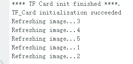
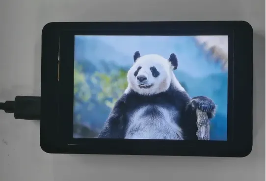
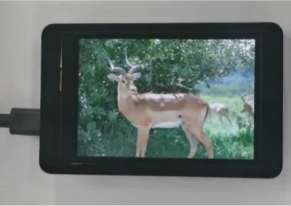
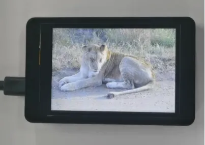
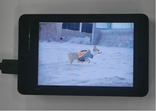
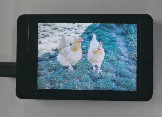
After the SD card is mounted successfully, the LCD displays the 5 BMP images from the SD card in a loop, with each image shown for about 5 seconds.
Note: The SD card experiment simultaneously depends on hardware contact, the file system, file paths, image format, and the screen library files. When troubleshooting, it is recommended to check the items in the following order: "Can the SD card be recognized by a computer → Are the files in the root directory → Do the filenames match → Is the image 320x240 / 24-bit → Is the Arduino environment configured correctly."
9. Code Download
- Code download link: SD_CrowPanel_ESP32_Advance_HMI_2.4_2.8
- 5 BMP image assets total link