2.4_2.8inch_Lesson07_LoRaWAN_AT_Parameter_Control
1. Course Introduction
This lesson completes the LoRaWAN communication setup between the ThinkNode-G1 gateway, the TTN platform, and the CrowPanel Advance wireless module. The lesson first connects the G1 gateway to Wi-Fi and configures the Packet Forwarder, then registers the gateway, creates an application, and adds an end device on the TTN platform. Finally, it uses the SSCOM serial tool to send AT commands to the development board, allowing the wireless module to join the LoRaWAN network via OTAA and upload data.
2. Learning Objectives
- Switch the ThinkNode-G1 gateway into configuration mode and connect it to Wi-Fi.
- Configure the LoRaWAN Packet Forwarder in the G1 local console.
- Register the G1 gateway on the TTN platform, and create an application and an OTAA end device.
- Use AT commands to configure the DevEUI, AppEUI, AppKey, and frequency band, and complete network join and data transmission.
- View the data uploaded by the node on the TTN Live data page.
3. Preparation
- CrowPanel Advance 2.4-inch development board.
- Wireless module – Meshtastic wireless module.
- ThinkNode-G1 LoRaWAN gateway.
- A Type-C USB data cable that supports data transfer.
- Arduino IDE with the ESP32 Arduino development environment.
- SSCOM serial debugging tool.
- The Things Network with a logged-in TTN account.
- Project:
sendATcommands_2.4_2_8.ino.
Code and Resource Download
Code download: - sendATcommands__2.4_2_8
4. Software Operation Steps
4.1 Overall Experimental Workflow
The software operations in this lesson follow this sequence: open the project and flash the program → configure the G1 gateway and the TTN platform → send AT commands using SSCOM → view the data on TTN.
- Open this lesson's project with Arduino IDE, and confirm the course library files have been placed in the Arduino
librariesdirectory as described in Lesson 01. - Configure the board, port, Flash Size, PSRAM, and Partition Scheme as shown in Lesson 01.
- Compile and flash the LoRaWAN AT program.
- Configure the ThinkNode-G1 gateway's network connection method and Packet Forwarder.
- Register the G1 gateway on the TTN platform, and create an Application and an End device.
- Use SSCOM to send AT commands, configure the node parameters, perform the network join, and send data.
- View the data uploaded by the node on the TTN Live data page.
4.2 Open the Project
Open the corresponding project file for the 2.4-inch / 2.8-inch board using Arduino IDE:
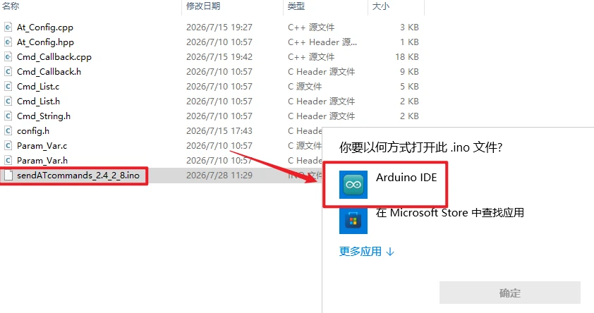
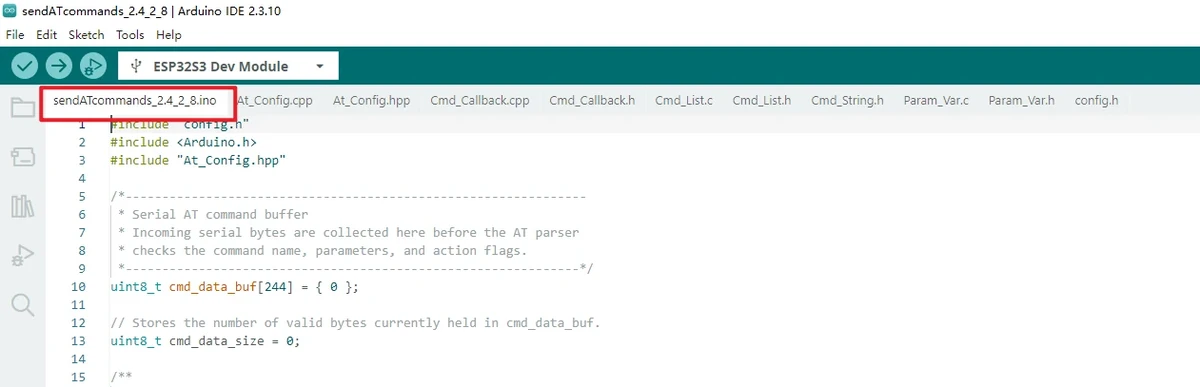
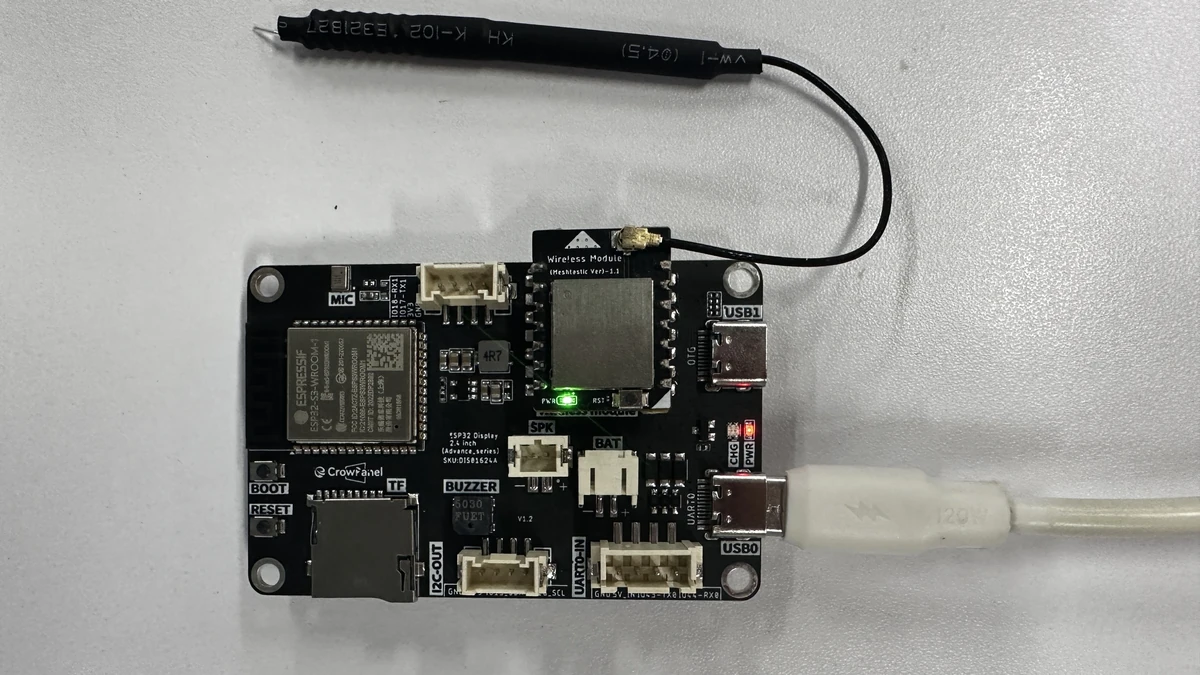
Insert the wireless module into the CrowPanel Advance development board, and connect the board to the computer using a Type-C USB cable that supports data transfer.
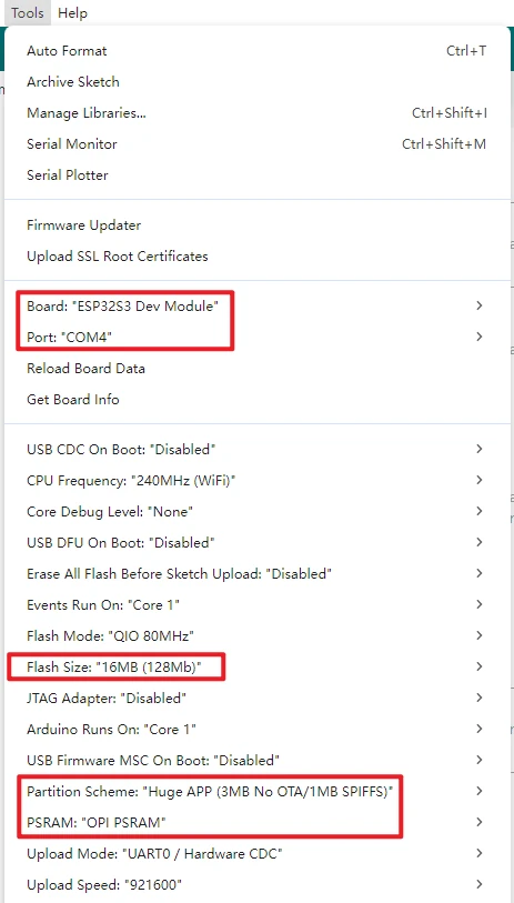
In the Arduino IDE Tools menu, confirm the following parameters. This configuration is consistent with Lesson 01:
Board: ESP32S3 Dev Module
Port: Select the serial port corresponding to the current board
Flash Size: 16MB (128Mb)
PSRAM: OPI PSRAM
Partition Scheme: Huge APP (3MB No OTA/1MB SPIFFS)
Serial Monitor baud: 115200
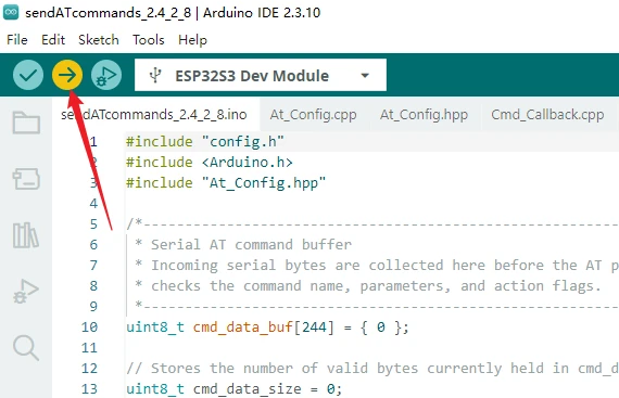
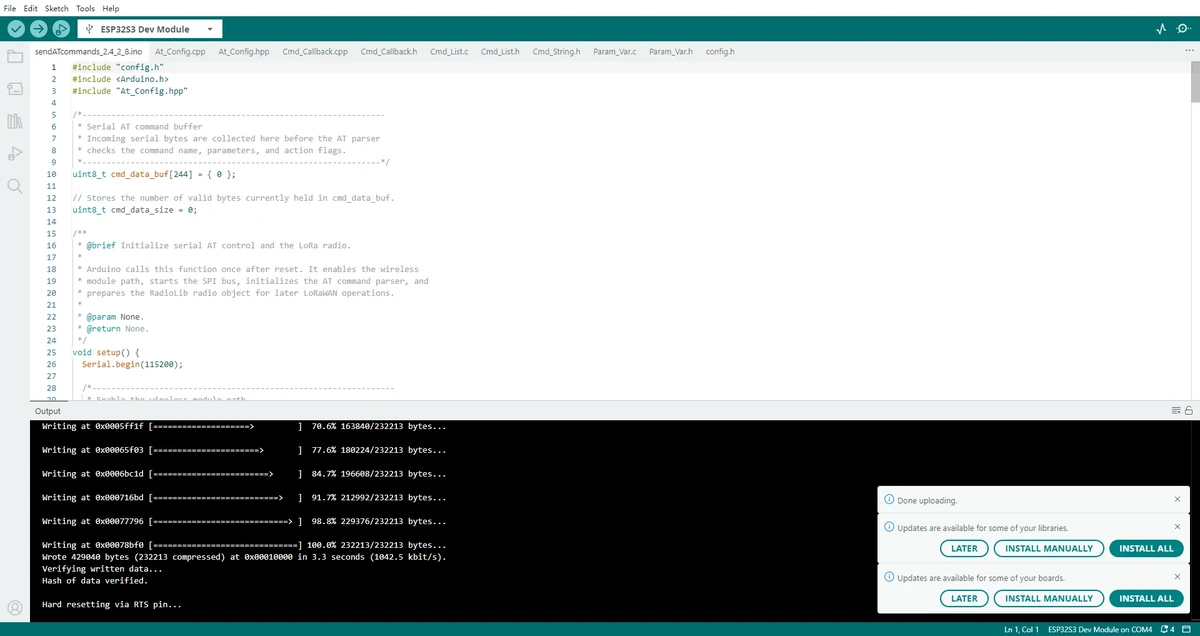
Click Upload to compile and wait for the upload to complete. If it is stuck at Connecting..., check for port conflicts and use the BOOT/RESET download mode as required by the board.
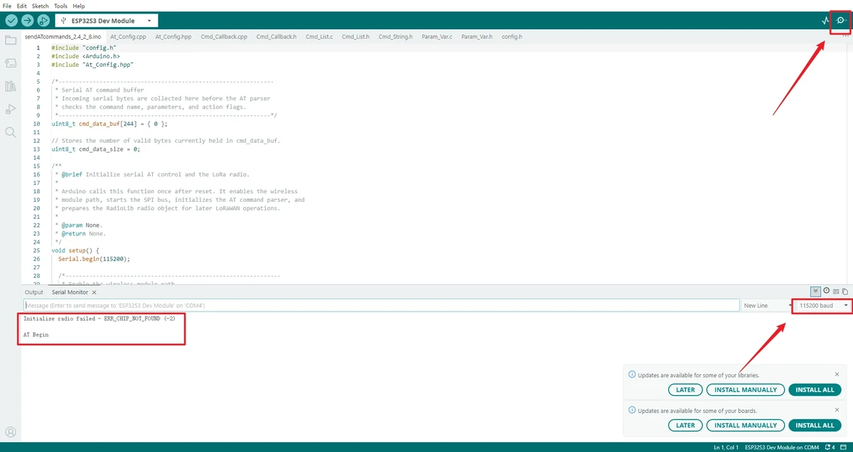
Open the Serial Monitor in the top-right corner, set the baud rate to 115200, and observe the log.
Note: If you find that the board behaves abnormally during the flashing stage, first remove the wireless module and then upload the program. Reinsert the module only after confirming that the program has been written successfully.
After the program is flashed, this lesson does not use the Arduino IDE Serial Monitor as the primary input tool. Instead, use SSCOM to send AT commands. Set the SSCOM baud rate to 115200 as well.
For 4.3-inch, 5.0-inch, and 7.0-inch screens, switch the Function Keys to the 01 position; for the 2.4-inch / 2.8-inch versions, follow the code of this lesson and the actual silkscreen marking on the board.
4.3 G1 Gateway Configuration, TTN Registration, End Device Creation, and SSCOM AT Commands
4.3.1 G1 Gateway Network Configuration
The G1 gateway supports three network connection methods: Ethernet, Wi-Fi, and 4G cellular network. Among them, 4G is only available on the 4G version. This lesson uses Wi-Fi as the example.
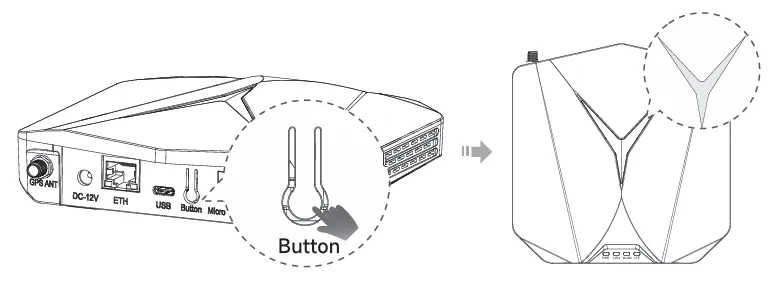
Press and hold the gateway button for about 5 seconds until the top indicator light blinks blue slowly, indicating the device has entered configuration mode.
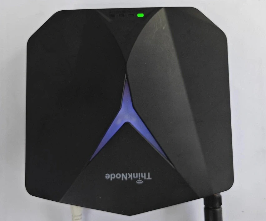
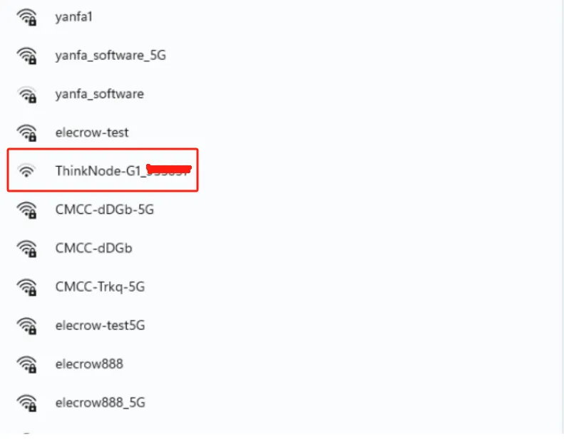
Connect to the AP hotspot. The hotspot name is ThinkNode-G1_XXXXXX, where XXXXXX is the 6-digit MAC address. This hotspot has no password by default and can be connected to directly.
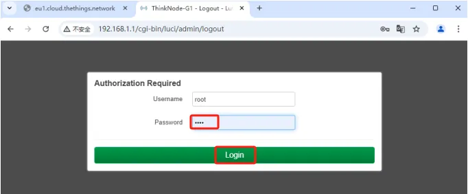
Enter 192.168.1.1 in the browser to access the local console. Enter root for both the username and password.
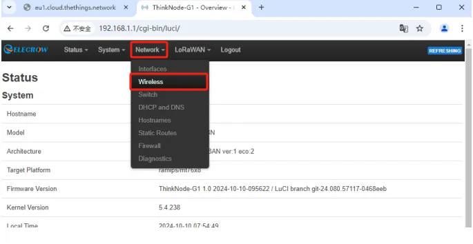
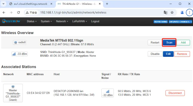
After logging into Luci, click Network > Wireless.
Click Scan to scan for nearby Wi-Fi networks.
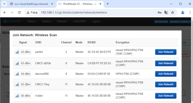
Select the Wi-Fi network to connect to, and click Join Network.
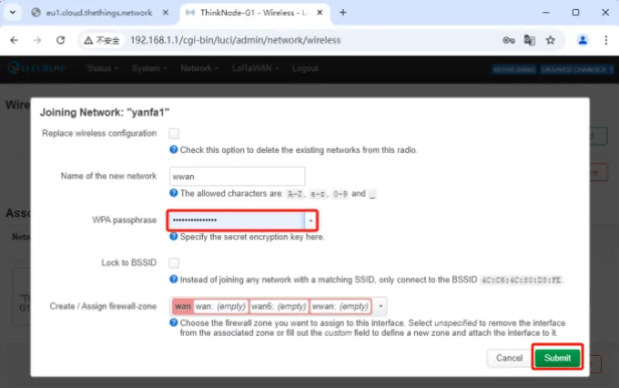
Enter the Wi-Fi password, click Submit, and then save the settings.
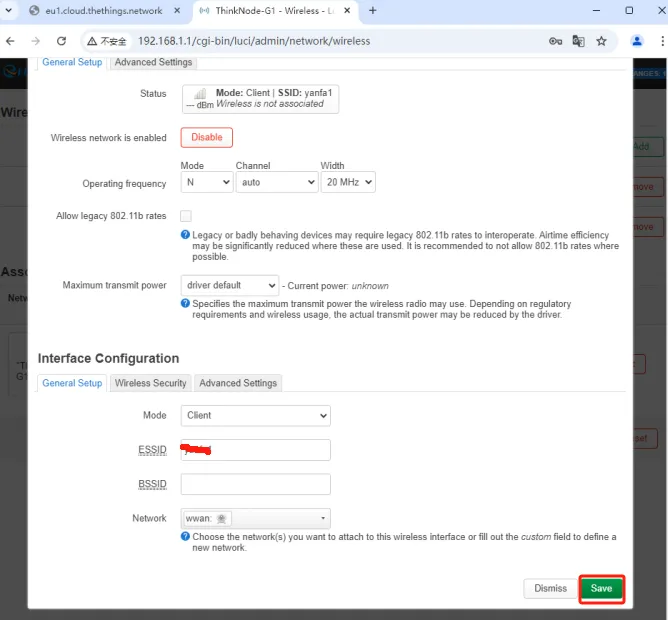
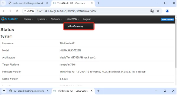
On the Luci page, click LoRaWAN, go to the LoRa Gateway page, and set the network configuration mode to WiFi.
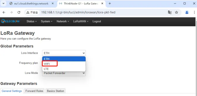
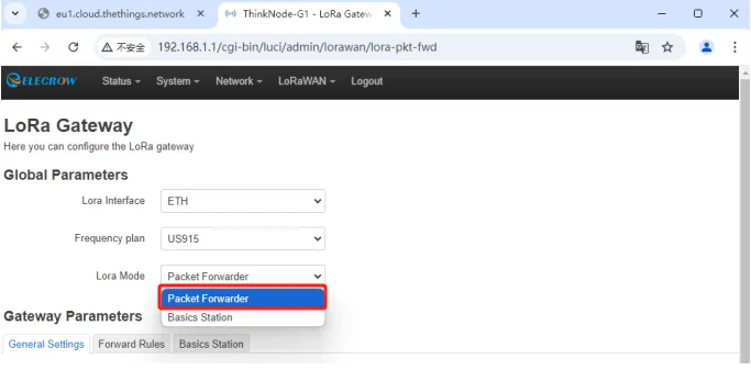
Set the gateway operating mode to Packet Forwarder.
Configure the Packet Forwarder. Gateway EUI is automatically obtained from the EUI of the currently connected gateway; enter the The Things Stack deployment address for Server address; Server Ports (Up/Down) is generally set to 1700.
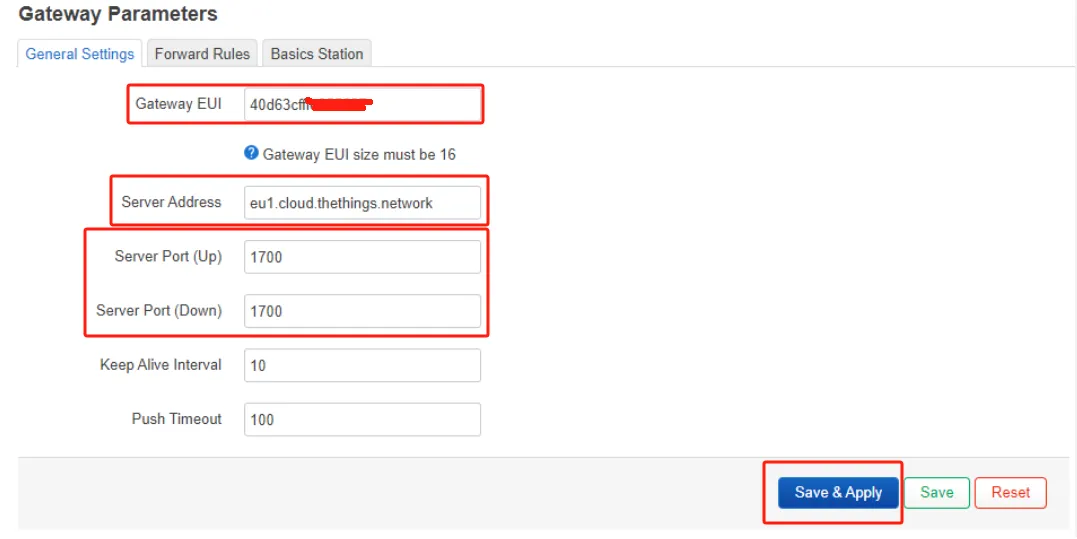
Configure the Region and Frequency plans, and click Save & Apply. The frequency band here must be consistent with the TTN platform and the end device AT commands.
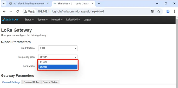
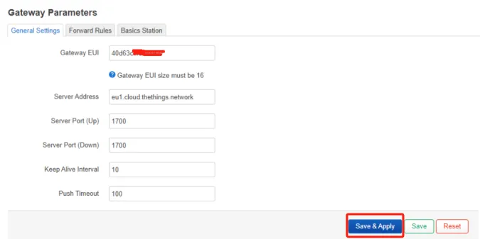
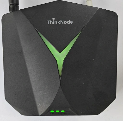
Double-click the gateway reset button and wait for the device to restart. If the gateway successfully connects to Wi-Fi, the green WLAN indicator light will stay on solid, and the top indicator light will also remain green.
4.3.2 Register the Gateway on the TTN Platform
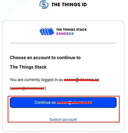
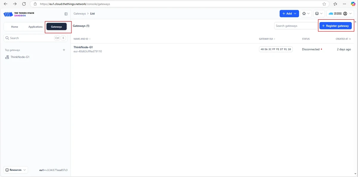
Open The Things Network and log in to your TTN account.
Register the gateway, enter the EUI, and click Confirm.
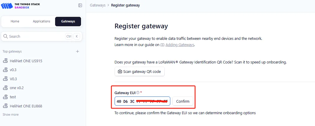
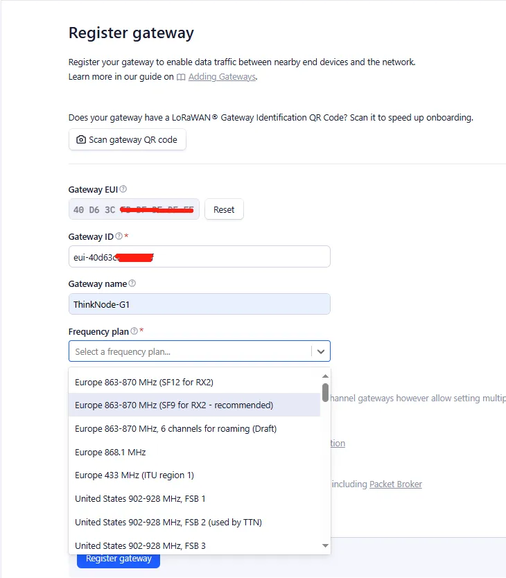
Gateway ID is typically written as eui-gatewayEUI, and may only use lowercase letters, numbers, and hyphens.
Fill in the Gateway Name, and select the Frequency Plan that matches your gateway version.
After successful registration, you can view the gateway status on the Overview page.
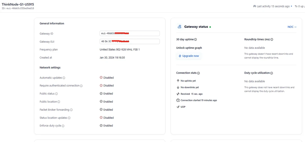
Double-click the gateway settings button and wait for the restart. The gateway will connect to TTN as a Packet Forwarder.
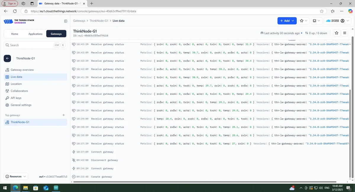
4.3.3 Create a TTN Node Application
In the TTN console, click Applications.
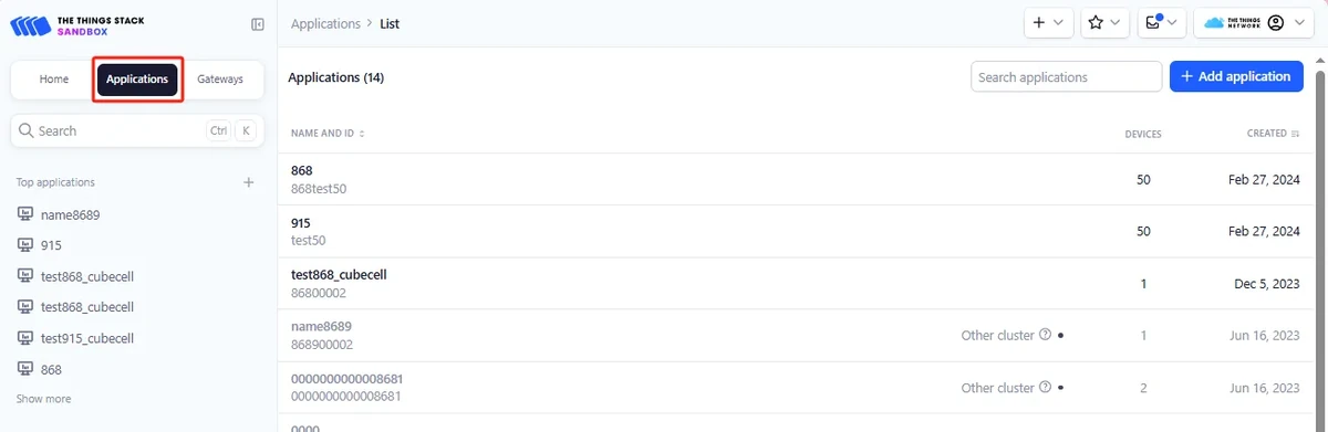
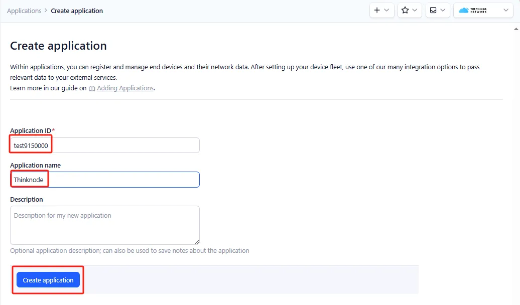
Click Add application, fill in the Application ID and Application name, then click Create application.
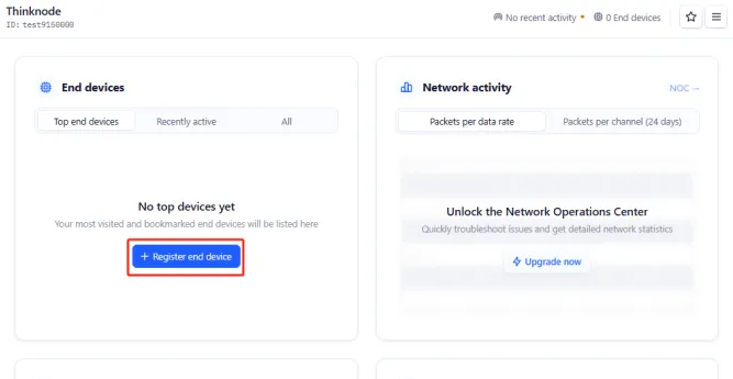
On the application Overview page, click Register end device.
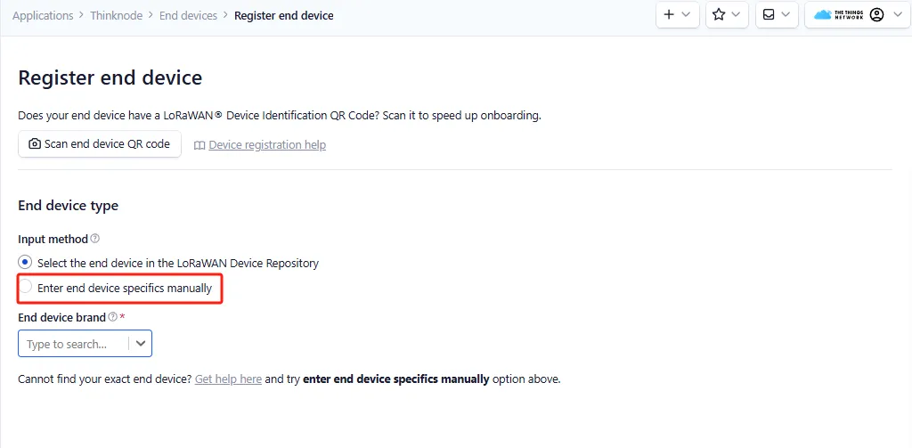
Select Enter end device specifics manually.
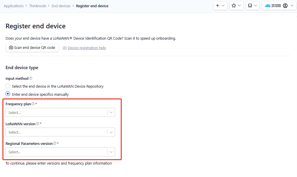
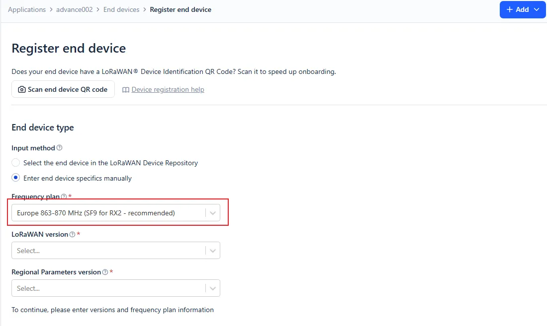
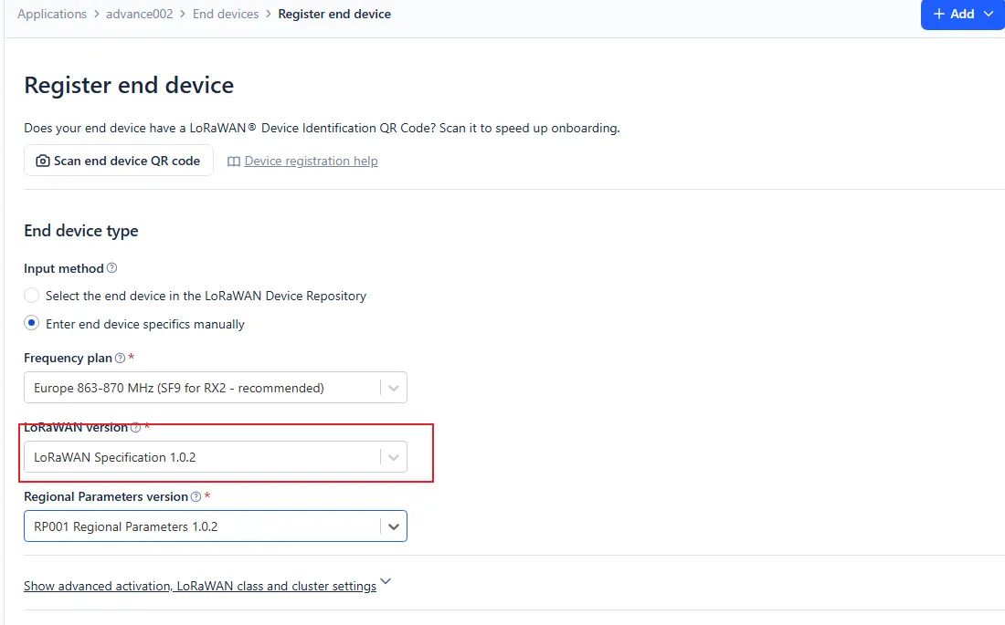
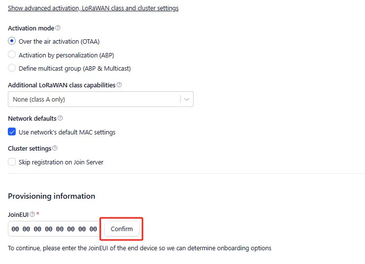
Set the Frequency plan, LoRaWAN version, Regional Parameters version, and JoinEUI.
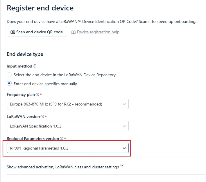
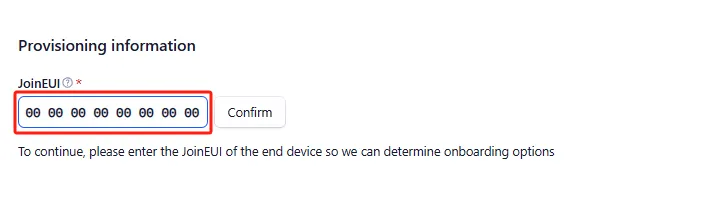
Expand the advanced settings, configure it to OTAA mode, and click Confirm.
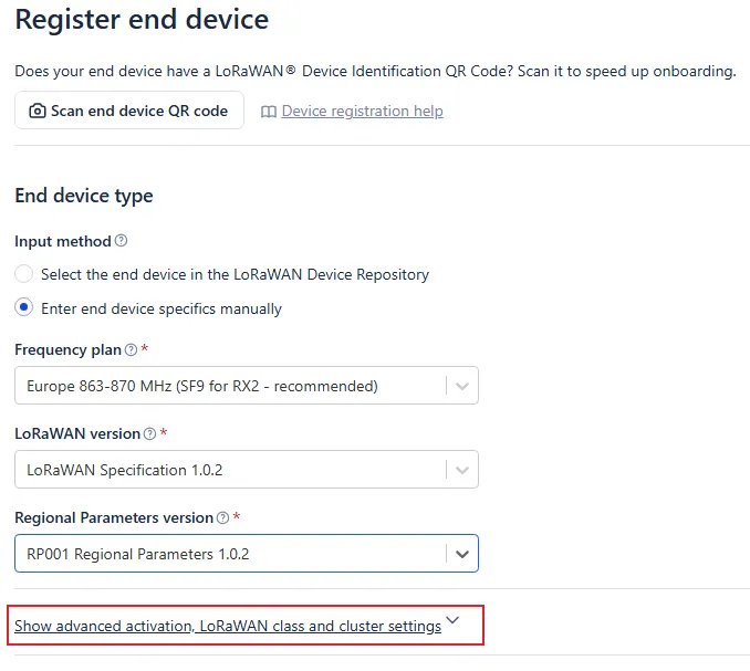
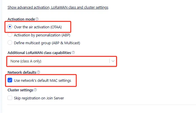
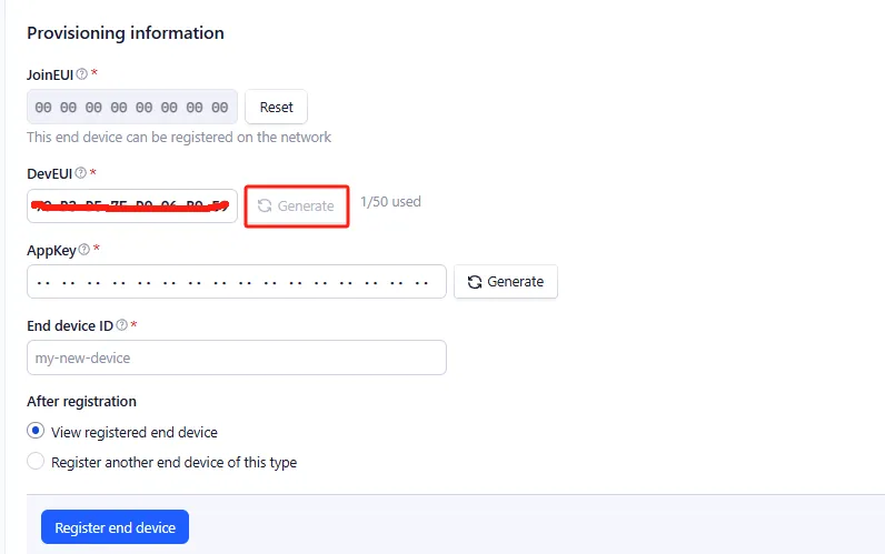
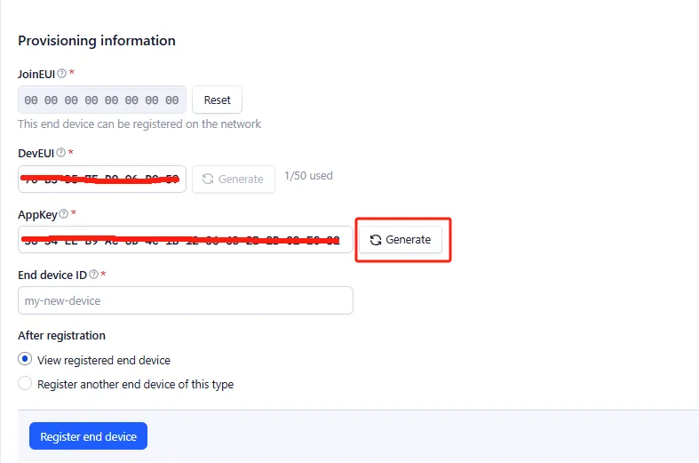
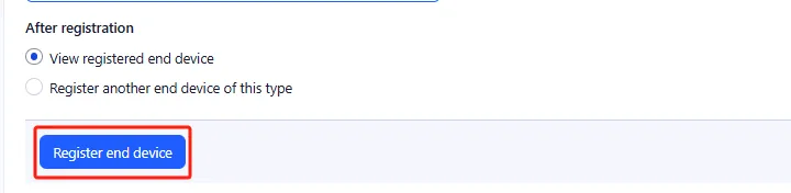
Click Generate to generate the DevEUI and AppKey, fill in the End device ID, then click Register end device.
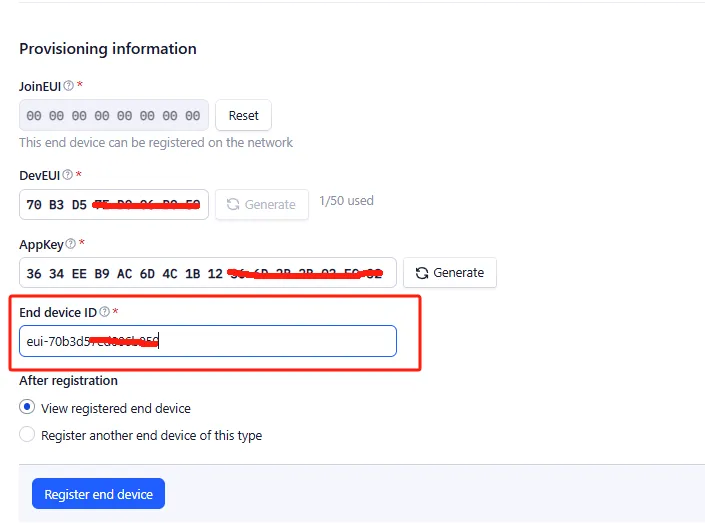
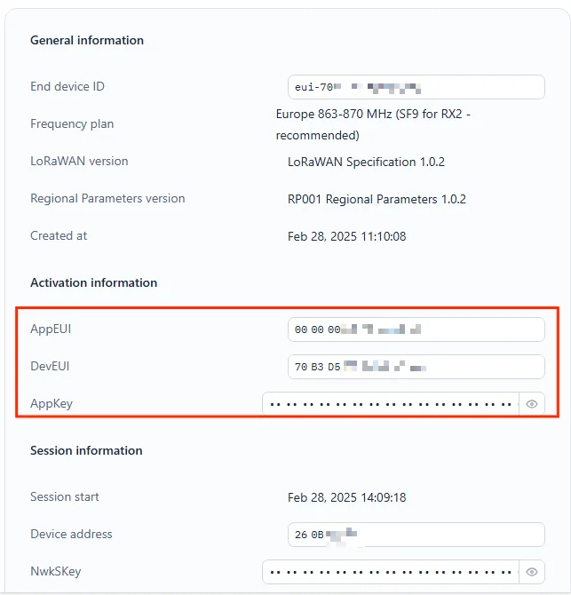
After registration, save the DevEUI, JoinEUI/AppEUI, and AppKey from the Activation information.
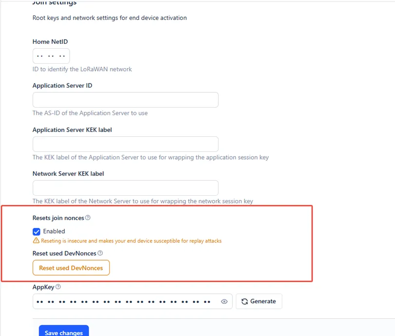
4.3.4 Resetting Join Nonces
To make repeated network join testing easier during experiments, you can enable Resets join nonces in the TTN device settings.
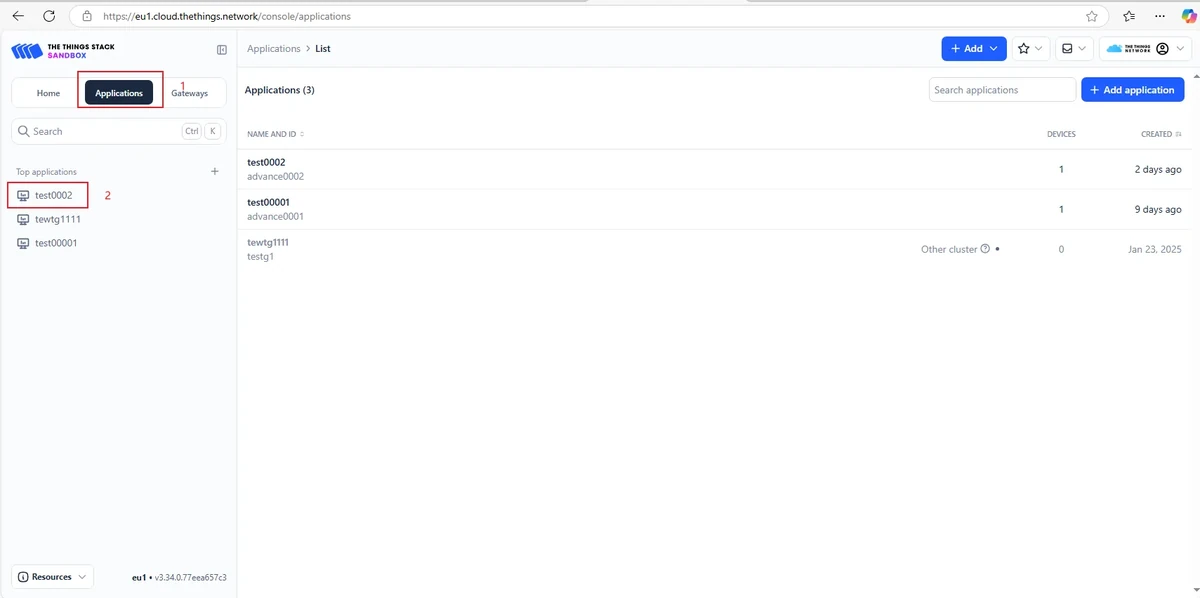
Go to Application > Application Name.
Click the node name to open Settings.
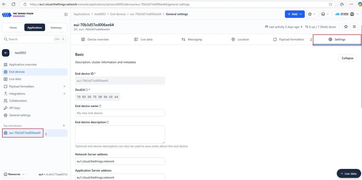
Scroll to the bottom of the page and expand Join Settings.
Remember to click "Save changes" to save your modifications.

Enable Resets join nonces.
4.3.5 Sending AT Commands Using SSCOM
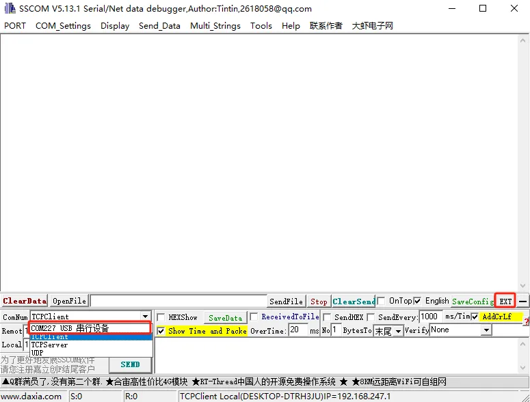
Open the SSCOM serial tool, select the USB COM port recognized by your computer, and then click EXT.
Set the serial parameters to 115200, check the newline (carriage return and line feed) option, and when opening the serial port, only check DTR.
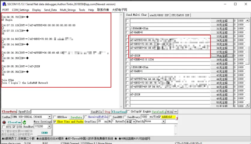
Send the following AT commands to configure the node parameters in order:
AT+BAND=0
AT+DEUI=70:B3:D5:7E:D0:06:****
AT+APPEUI=AA:AA:AA:AA:AA:AA:****
AT+APPKEY=49:0F:B4:80:37:F0:5E:6C:5C:B3:24:F5:B5:78:****
Here, DevEUI, AppEUI, and AppKey should be replaced with the actual values from the TTN page.
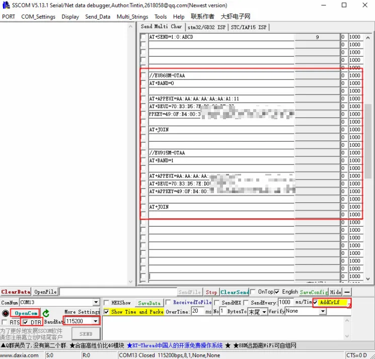
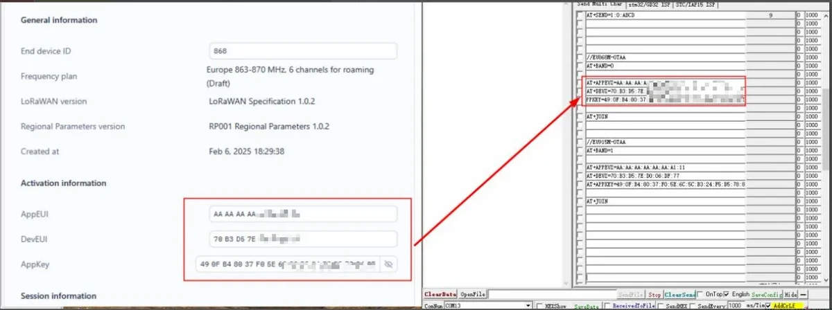
Send the network join command AT+JOIN and wait for the node to successfully join the network.
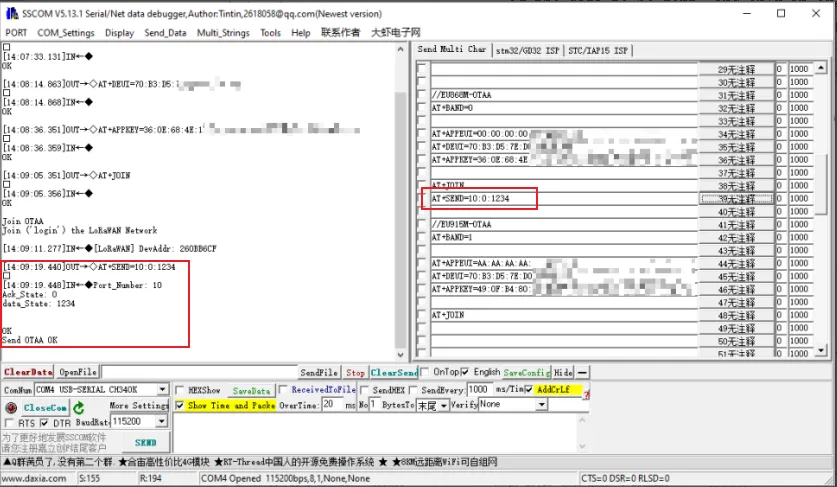
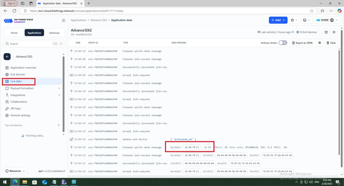
Send the data AT+SEND=10:0:1234, then view the data reported by the node on the Applications > Live data page in TTN.
5. Hardware Operation Steps
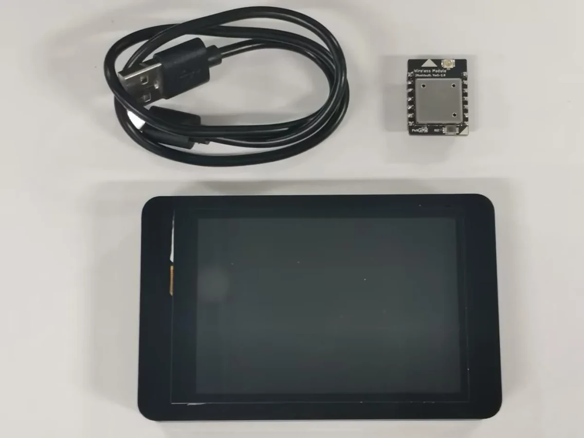
Insert the Wireless module-Meshtastic block into the W-M wireless module slot on the development board, and connect the CrowPanel Advance development board using a USB data cable.
6. Key Code Explanation
These lines are used to switch the wireless module path and initialize the SPI bus. GPIO45 is used to select the wireless module channel, and the SPI pin configuration comes from config.h.
This section uses RadioLib to initialize the SX1262 wireless chip and set the current limit and TCXO. If the wireless chip fails to initialize, subsequent AT commands, even if successfully parsed, will be unable to perform the actual LoRaWAN transmission.
if (OTAA_Join_Flag == 1) {
  node.beginOTAA(app_param.lora_info.JoinEui, app_param.lora_info.DevEui, NULL, app_param.lora_info.AppKey);
  state = node.activateOTAA(joinDR);
}
When the serial port receives AT+JOIN and OTAA mode is selected, the program initiates a network join to the LoRaWAN network using JoinEUI/AppEUI, DevEUI, and AppKey.
state = node.sendReceive(MsgTemp, MsgTemp_size, Port_Number, downlinkPayload, &downlinkSize, true, &uplinkDetails, &downlinkDetails);
After the serial port receives AT+SEND, the program uploads the data to be sent via LoRaWAN and waits to see whether any downlink data is returned.
7. Experimental Observations
After the end device is successfully configured, sending AT+JOIN in SSCOM will display the network join related logs; after sending AT+SEND=10:0:1234, the data reported by the node can be viewed on the Applications > Live data page in TTN.
If the network join fails, please check the following items first:
- Whether the frequency band is consistent among the G1 gateway, the TTN gateway, the TTN end device, and the AT commands.
- Whether the
Gateway EUIis correctly entered into TTN. - Whether
DevEUI,JoinEUI/AppEUI, andAppKeyexactly match the TTN end device page. - Whether the G1 gateway is connected to the network and properly linked to TTN.
- Whether SSCOM uses a baud rate of
115200and appends a carriage return and line feed when sending. - Whether the wireless module is correctly inserted into the development board, and whether the development board ports and hardware connections were completed as described in Lesson 1.
8. Code Download
Code download link: sendATcommands__2.4_2_8