2.4_2.8inch_Lesson05_SD_Card_Image_Display
1. Course Introduction
In this lesson, we use the onboard SD card slot of the CrowPanel Advance 2.4inch ESP32-S3 HMI to read BMP images and display them in a loop on the LCD screen. After the experiment runs, the screen first shows the SD card initialization result. Once initialization succeeds, it displays 1.bmp through 5.bmp from the SD card root directory in sequence, with each image shown for about 5 seconds.
The focus of this lesson is not downloading images over the network, but having the development board read image files from a local SD card. This approach can be used for scenarios such as product boot splash screens, offline photo albums, menu background images, and background pages for sensor data displays.
This lesson's project runs in ESP-IDF 5.5.4, with the target chip set to esp32s3.
2. Learning Objectives
- Be able to prepare the SD card, card reader, and BMP image assets.
- Be able to process ordinary images into the
320 x 240resolution required by the 2.4inch / 2.8inch screens. - Be able to save images as 24-bit BMP format.
- Be able to place
1.bmpthrough5.bmpinto the SD card root directory. - Be able to understand the LCD status prompts, SD card initialization, directory scanning, and line-by-line BMP display flow in the updated ESP-IDF code.
- Be able to determine whether SD card mounting, file reading, and image display are working properly based on the LCD prompts and serial logs.
3. What You Need to Prepare
3.1 Hardware and Accessories
- One CrowPanel Advance 2.4inch Version 1.1 / 1.2 ESP32-S3 HMI development board.
- One USB Type-C data cable that supports data transfer, used for power, flashing the program, and viewing serial logs.
- One Micro SD / TF card, used to store BMP images.
- One USB card reader, used to copy images onto the SD card from a computer.
- One computer, used to process images, copy files, and flash the ESP-IDF program.
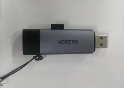
Note: It is recommended to format the SD card as FAT32 first. If your computer cannot reliably recognize the SD card, the development board will likely also fail to mount it properly.
3.2 Software and Files
- VS Code, the ESP-IDF extension, and
ESP-IDF 5.5.4already installed in Lesson01. - Windows Paint, or another image tool that can adjust pixel dimensions and export 24-bit BMP.
Note: This tutorial targets the 2.4inch Version 1.1 / 1.2, and also applies to the 2.8inch project with the same resolution. Both the 2.4inch and 2.8inch displays have a resolution of 320 x 240, so the BMP image size and the width/height parameters in the code can remain consistent.
Code and Resource Download
Code download: - Lesson05-SD_Images_24_28
Resource download:
4. SD Card Preparation and BMP Image Processing
In this lesson, "image processing" and "SD card file preparation" are completed within the same major section. First, process the images into BMP files that the development board can read directly, then copy the files to the SD card root directory as required by the code, and finally move on to the ESP-IDF software operations.
4.1 Overall Processing Sequence
- Prepare the images you want to display, or use the
picture_materialssample images provided with the course. - Use an image tool to resize the images to
320 x 240. - Save the images as 24-bit BMP format.
- Name the images
1.bmp,2.bmp,3.bmp,4.bmp,5.bmp. - Use the card reader to copy the BMP images to the SD card root directory.
- Safely eject the SD card, then insert it into the SD card slot of the CrowPanel Advance HMI.
- Open the ESP-IDF project and confirm the image paths, display dimensions, and carousel dwell time in the code.
- Compile and flash the program, then observe the SD card status prompts and image carousel effect on the LCD.
4.2 Image Preparation
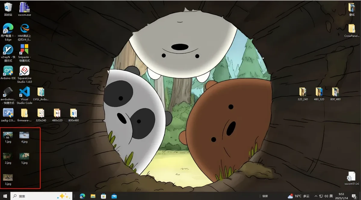
Choose an image you want to display on the screen. You may use an image you downloaded yourself, or directly use the sample assets provided with this course. You can first save the image to the desktop or another easy-to-find location.
The official tutorial provides image resolutions corresponding to different screen sizes. The 2.4inch / 2.8inch screens used in this course have a resolution of 320 x 240.
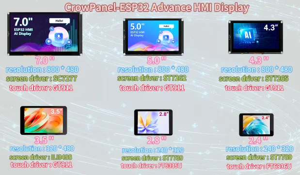
Note: For 2.4inch / 2.8inch, use 320 x 240. The actual image size, the displayImage(..., 320, 240) parameters in the code, and the screen orientation must remain consistent, otherwise you may encounter garbled display, misalignment, or only part of the image showing.
4.3 Open the Image Processing Tool
Open the "Paint" tool in Windows.
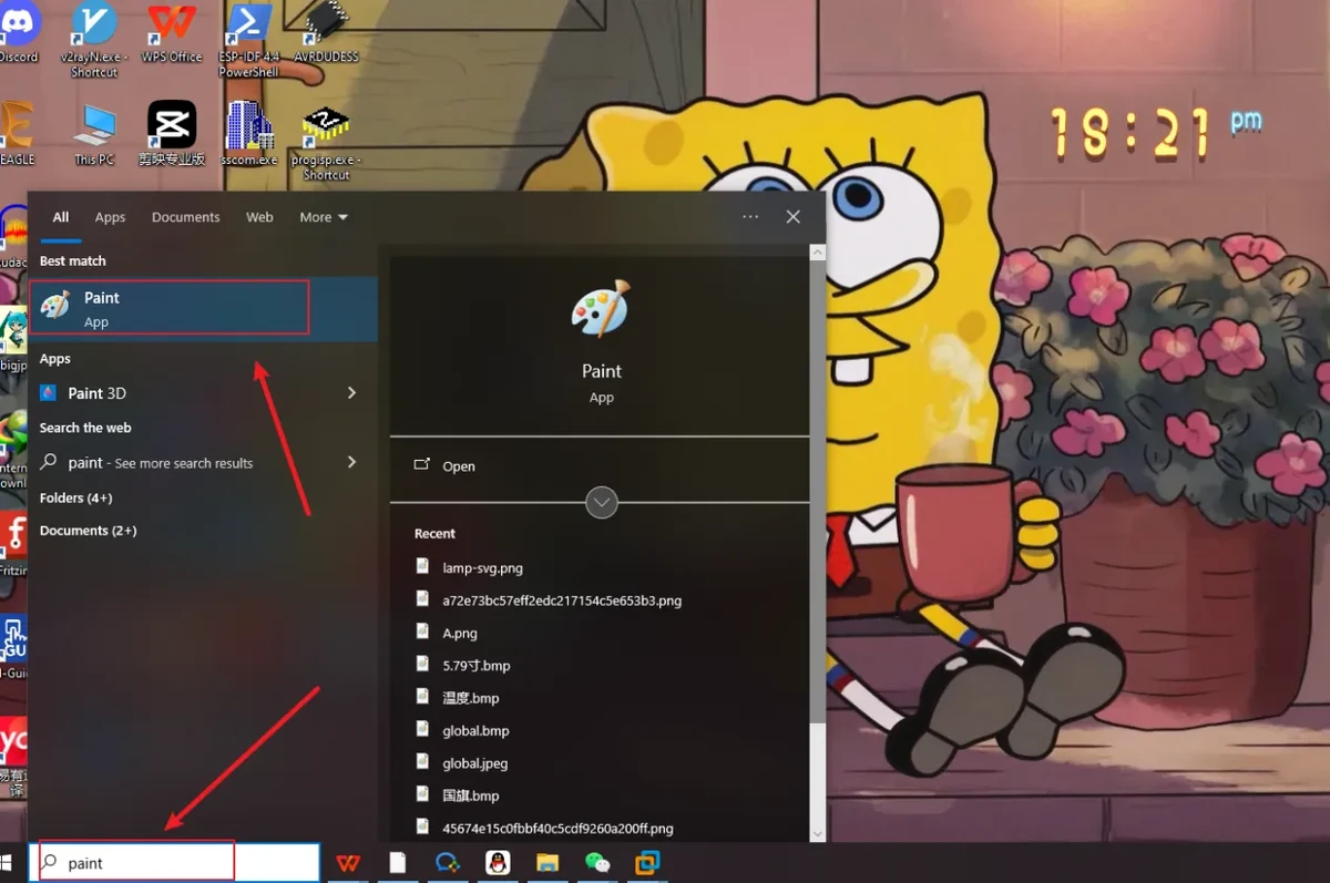
Drag the prepared image into Paint, or use Paint's Open function to select the image file.
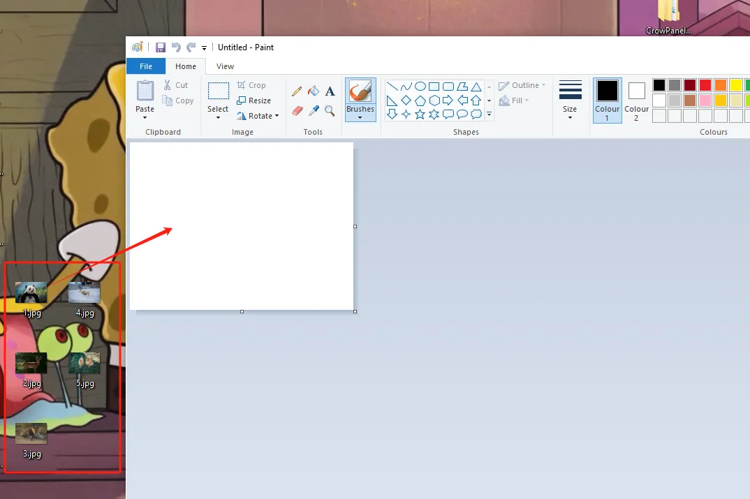
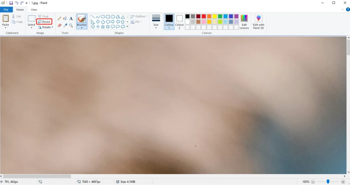
4.4 Adjust Image Pixel Dimensions
Click the Resize function in Paint, switch the unit to pixels, then set the horizontal and vertical dimensions to:
The figure below is for illustration purposes. Please adjust the appropriate resolution according to the different sizes you are actually using.
-
(Resolution for 4.3-inch, 5.0-inch, and 7.0-inch screens: 800x480)
-
(Resolution for 3.5-inch screen: 480x320)
-
(Resolution for 2.4-inch and 2.8-inch screens: 320x240)
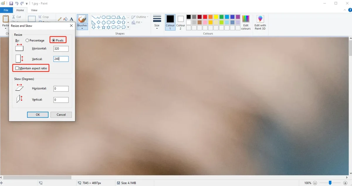
Click OK to finish resizing the image.
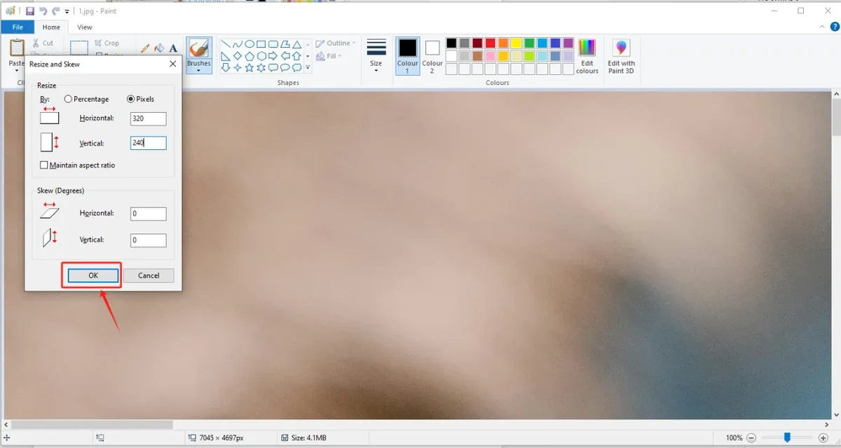
After resizing, check whether the image proportions and content meet your expectations.
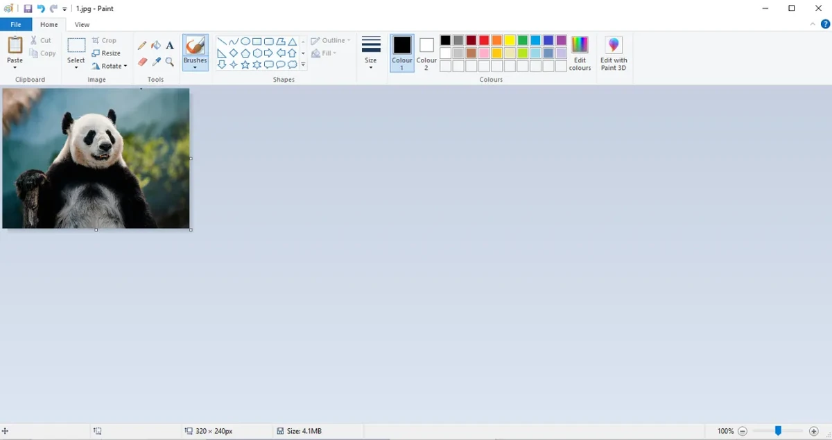
4.5 Save as 24-bit BMP
Choose Save As, and save the processed image to an easy-to-find location on your computer.
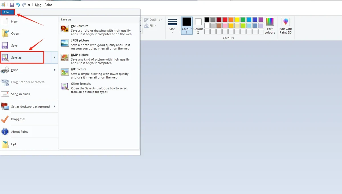
Select BMP as the save format, and make sure the image depth is 24-bit. It is recommended to name them 1.bmp, 2.bmp, 3.bmp, 4.bmp, 5.bmp following the default code paths.
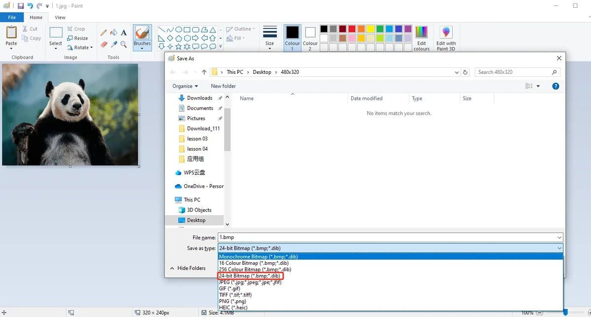
Note: Do not simply change the file extension. You must use an image tool to save it as BMP, and confirm it is 24-bit image depth.
4.6 Copy Images to the SD Card
Insert the Micro SD / TF card into the card reader, then connect the card reader to your computer.
Open the SD card drive and copy the processed 1.bmp through 5.bmp to the SD card root directory.
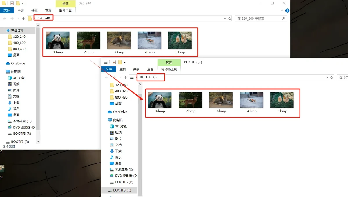
The recommended SD card root directory structure is as follows:
After copying is complete, safely eject the SD card and remove it from the card reader, then insert it into the SD card slot of the CrowPanel Advance HMI 2.4inch.
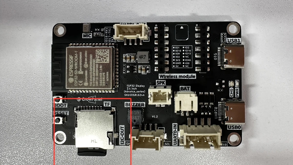
Note: The default code for this lesson reads the SD card root directory paths /1.bmp through /5.bmp, so do not place the images in subfolders. The file names must match the code exactly; it is recommended to use English and numbers for naming, avoiding Chinese characters, spaces, and special symbols.
5. ESP-IDF Software Operation Steps
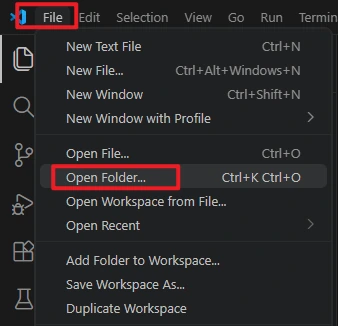
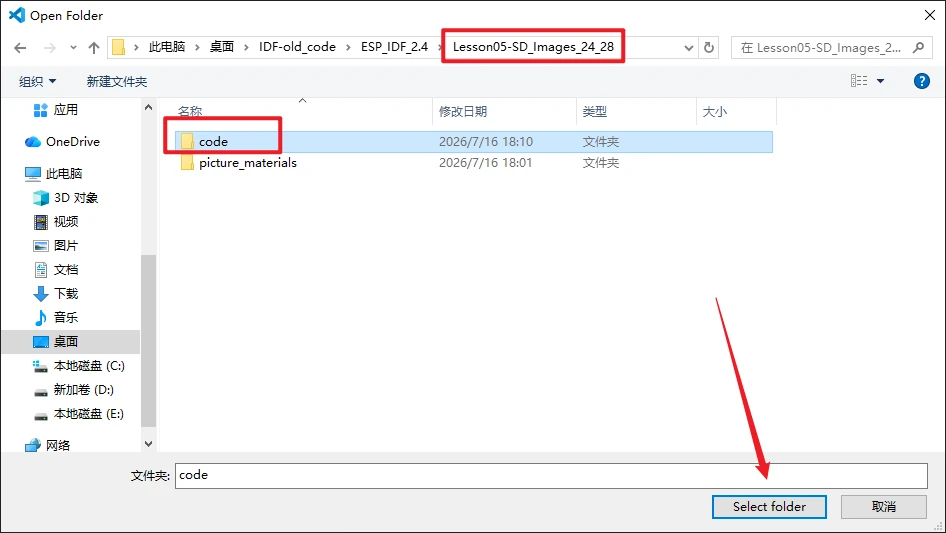
In VS Code, select File -> Open Folder... and open the root directory of this lesson's ESP-IDF project.
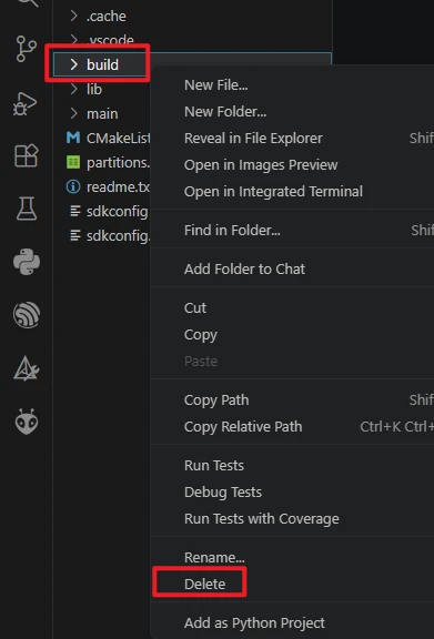
After opening the project, first run Build -> Delete to clear the build cache and path records generated by the old project. It is recommended to do this step after switching computers, switching ESP-IDF versions, or copying the project.
Confirm that VS Code has loaded ESP-IDF 5.5.4. If the version shown in the status bar or ESP-IDF extension is incorrect, return to the installation steps in Lesson01 and reselect the 5.5.4 environment.

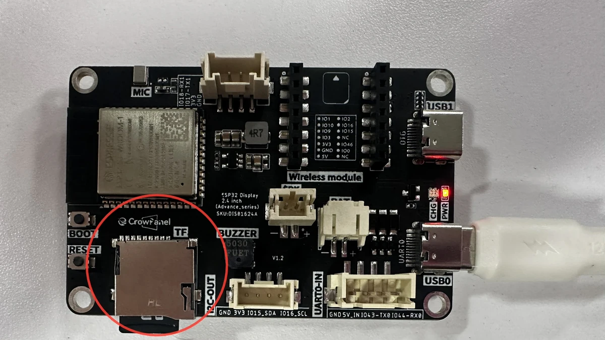
Insert the SD card into the development board's TF card slot, and connect the development board to the computer using a USB cable that supports data transfer.
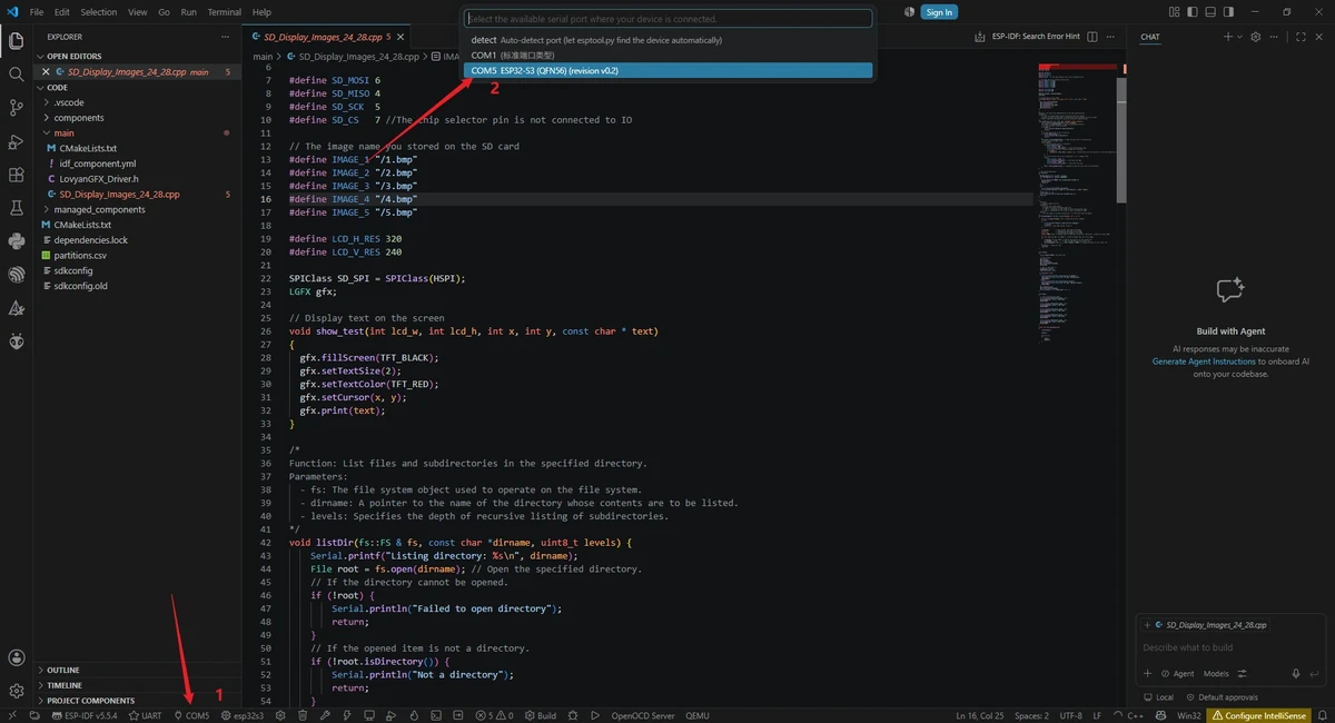
Click the serial port location in the VS Code bottom status bar and select the actual COM port recognized by your computer.
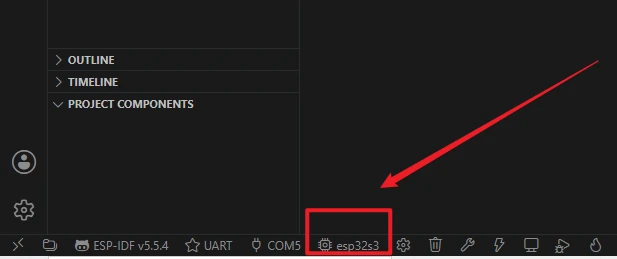
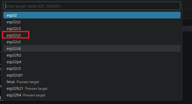
Click the target chip location in the status bar, or run the command ESP-IDF: Set Espressif Device Target, and select esp32s3 as the target chip. The reference images are for illustrating the entry points; the actual selection should follow this course's esp32s3.
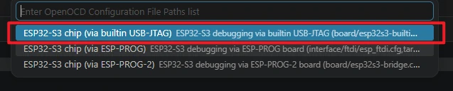
When selecting the debug configuration, choose the one that matches the ESP32-S3 development board, such as the ESP32-S3 built-in USB-JTAG or the corresponding ESP32-S3 OpenOCD configuration. Ordinary UART flashing mainly relies on the serial port and correct target chip settings.
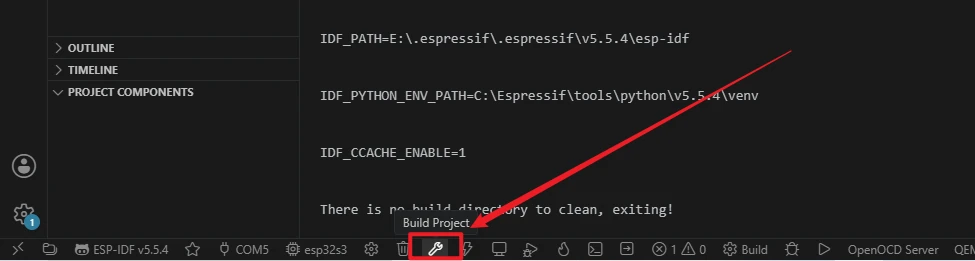
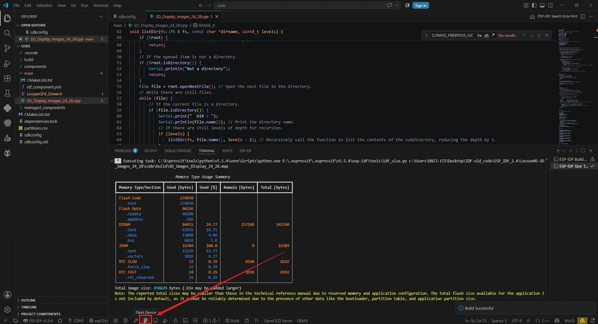
Click the Build button in the status bar to start compiling, or run the following in the ESP-IDF terminal:
The first build needs to download and generate dependencies, so it will take longer; continue with flashing only after you see the Build success message.
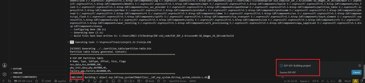
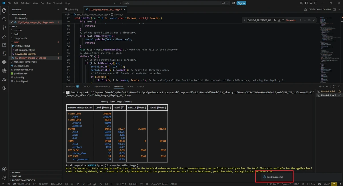
Confirm the flashing method is UART, then click the lightning icon Flash, or run the following in the ESP-IDF terminal:
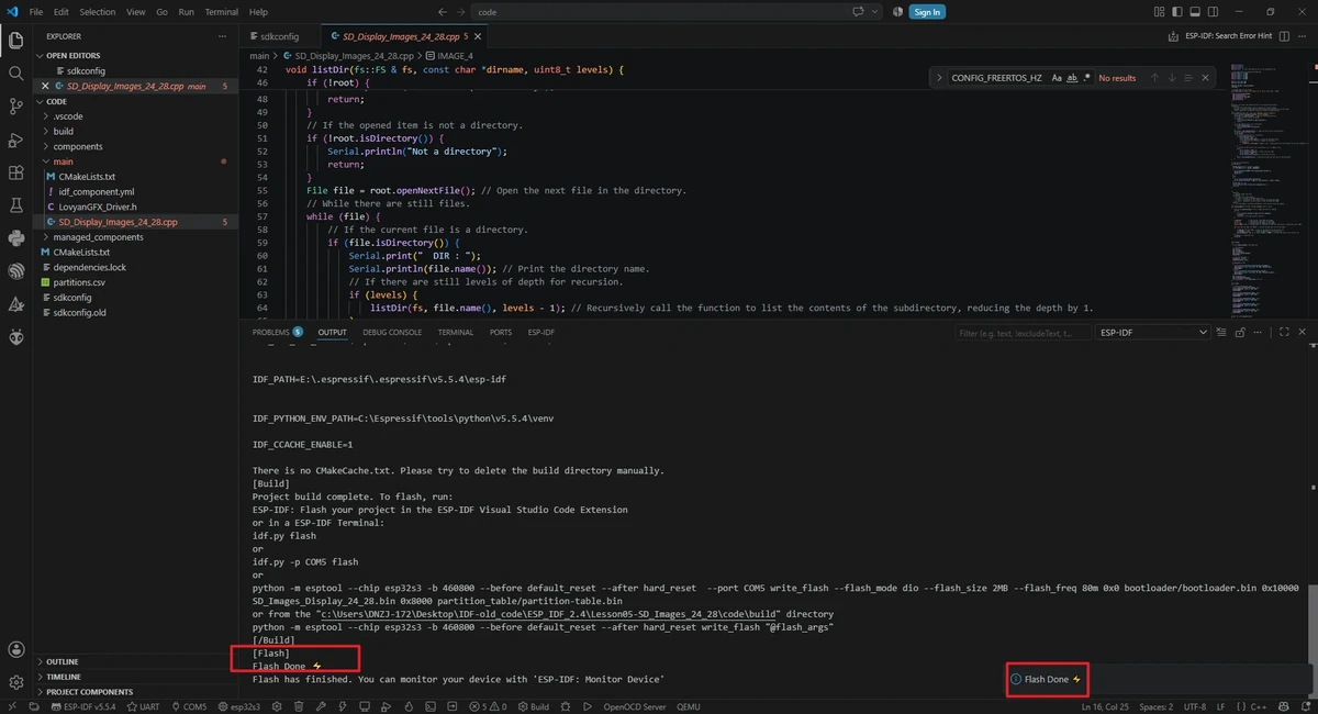
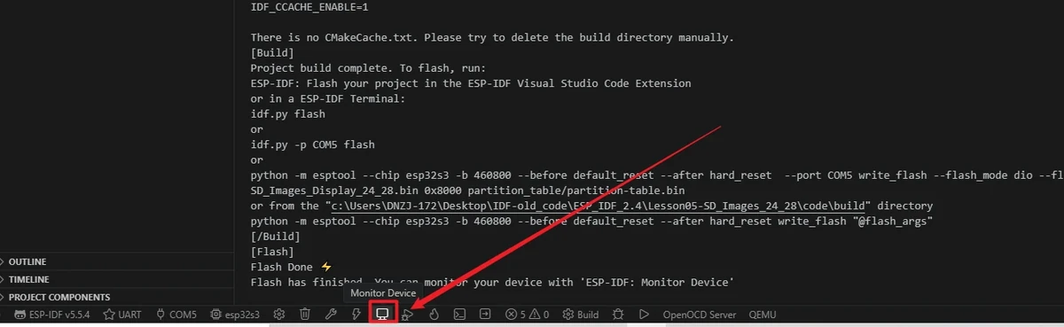
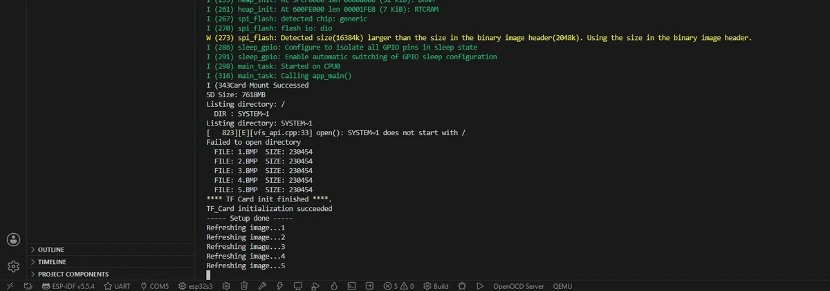
After flashing completes, click Monitor. If you see Card Mount Successed, SD Size, Listing directory: /, and the file list of 1.bmp through 5.bmp in the serial output, it means SD card mounting and file preparation are basically working. At this point, the LCD will first display SD_Card OK, then enter the image carousel.
6. Key Code Explanation
The current code for this lesson is located in Lesson05-SD_Images_24_28/code/main. The project is compiled with ESP-IDF, but the main file is C++, and it reuses file system interfaces such as SPI.h, FS.h, and SD.h through the Arduino component; screen display is handled by the LovyanGFX configuration in LovyanGFX_Driver.h. The program flow is: initialize the Arduino runtime, initialize the LCD and SD card, scan the SD card directory, then loop through reading 1.bmp through 5.bmp and display them on the screen.
6.1 Using the Arduino Component in ESP-IDF
app_main() is the ESP-IDF entry point. The current project first calls initArduino() so that the Arduino core's GPIO, SPI, Serial, delay, and SD file system interfaces can be used normally; then it runs setup() once; finally it loops loop(). Therefore, although this lesson uses ESP-IDF for building and flashing, the code structure still retains the Arduino style, making it easy to reuse mature SD and LovyanGFX sample code.
This can also be seen in main/CMakeLists.txt: the project compiles SD_Display_Images_24_28.cpp and depends on the arduino-esp32 and LovyanGFX-master components, while also defining LGFX_USE_V1.
6.2 SD Card Pins and Image File Names
#define SD_MOSI 6
#define SD_MISO 4
#define SD_SCK  5
#define SD_CS   7

#define IMAGE_1 "/1.bmp"
#define IMAGE_2 "/2.bmp"
#define IMAGE_3 "/3.bmp"
#define IMAGE_4 "/4.bmp"
#define IMAGE_5 "/5.bmp"

SPIClass SD_SPI = SPIClass(HSPI);
LGFX gfx;
The SD card uses a separate SPI bus object SD_SPI, with MOSI=GPIO6, MISO=GPIO4, SCK=GPIO5, CS=GPIO7. The image files must be placed in the SD card root directory, and the file names must match the macro definitions exactly, for example /1.bmp, /2.bmp. LGFX gfx is the screen object, and all subsequent screen clearing, text, and image display are done through it.
6.3 LovyanGFX Screen Driver Configuration
class LGFX : public lgfx::LGFX_Device
{
   lgfx::Panel_ST7789 _panel_instance;
   lgfx::Bus_SPI      _bus_instance;
   lgfx::Touch_FT5x06 _touch_instance;
The current LovyanGFX_Driver.h uses the ST7789 panel, SPI bus, and FT5x06 touch configuration. The screen SPI uses SPI2_HOST, with a write frequency of 80 MHz, SCLK=GPIO42, MOSI=GPIO39, DC=GPIO41, CS=GPIO40. The panel visible size is configured as 240 x 320, and parameters such as offset_rotation = 3 and invert = true are used to adapt the current screen orientation and color display.
In the panel configuration, bus_shared = true means the screen bus is allowed to coexist with other device scenarios. Although this lesson's SD card uses the independent SD_SPI object, keeping this setting makes LovyanGFX's SPI transaction handling more robust.
The touch part uses I2C: SDA=GPIO15, SCL=GPIO16, INT=GPIO47, address 0x38, frequency 400 kHz. This lesson mainly demonstrates SD images and does not use touch interaction, but the touch configuration is still kept in the driver for easier expansion in later lessons.
6.4 Screen and SD Card Initialization
void setup()
{
  Serial.begin(115200);

  gfx.init();
  gfx.initDMA();
  gfx.startWrite();
  gfx.fillScreen(TFT_BLACK);
  delay(500);

  pinMode(38, OUTPUT);
  digitalWrite(38, HIGH);

  if (SD_init() == 0)
  {
    Serial.println("TF_Card initialization succeeded");
    show_test(LCD_H_RES, LCD_V_RES, 75, 100, "SD_Card OK");
    delay(3000);
  } else {
    Serial.println("TF card initialization failed");
    show_test(LCD_H_RES, LCD_V_RES, 75, 100, "SD_Card failed");
    delay(3000);
  }
  gfx.setRotation(2);
  gfx.fillScreen(TFT_BLACK);
  Serial.println( "----- Setup done -----" );
}
The setup() function first opens the serial port, then initializes the LCD, DMA, and the write transaction, after which it clears the screen to black and enables the GPIO38 backlight/screen enable. SD_init() returns 0 to indicate successful SD card mounting, and the screen displays SD_Card OK; it returns 1 to indicate failure, and the screen displays SD_Card failed. Finally, gfx.setRotation(2) sets the display orientation and clears the screen again before entering the image slideshow.
6.5 Status Text Display
void show_test(int lcd_w, int lcd_h, int x, int y, const char * text)
{
  gfx.fillScreen(TFT_BLACK);
  gfx.setTextSize(2);
  gfx.setTextColor(TFT_RED);
  gfx.setCursor(x, y);
  gfx.print(text);
}
show_test() is used to display the SD card initialization status. Among the parameters, lcd_w and lcd_h are currently not used in any calculation; the actual text position is controlled by x and y. On initialization success or failure, the program passes (75, 100, "SD_Card OK") and (75, 100, "SD_Card failed") respectively, making it easy to determine whether the SD card was mounted successfully without having to check the serial monitor.
6.6 SD Card Mounting
int SD_init()
{
  SD_SPI.begin(SD_SCK, SD_MISO, SD_MOSI);
  if (!SD.begin(SD_CS, SD_SPI, 80000000))
  {
    Serial.println(F("ERROR: File system mount failed!"));
    SD_SPI.end();
    return 1;
  }
  else
  {
    Serial.println("Card Mount Successed");
    Serial.printf("SD Size: %lluMB \n", SD.cardSize() / (1024 * 1024));
  }
  listDir(SD, "/", 2);
  Serial.println("**** TF Card init finished ****.");
  return 0;
}
SD_SPI.begin() starts the SPI bus according to the actual pins of the SD card slot. SD.begin() mounts the file system using the CS pin, the SPI object, and an 80 MHz frequency. On failure, it closes the SD SPI and returns 1; on success, it prints the SD card capacity and then calls listDir(SD, "/", 2) to scan the root directory. This directory scan is important because it lets you confirm in advance whether the files 1.bmp through 5.bmp actually exist on the SD card.
6.7 Directory Scanning
void listDir(fs::FS & fs, const char *dirname, uint8_t levels) {
    Serial.printf("Listing directory: %s\n", dirname);
    File root = fs.open(dirname);
    if (!root) {
        Serial.println("Failed to open directory");
        return;
    }
    if (!root.isDirectory()) {
        Serial.println("Not a directory");
        return;
    }

    File file = root.openNextFile();
    while (file) {
        if (file.isDirectory()) {
            Serial.print("  DIR : ");
            Serial.println(file.name());
            if (levels) {
                listDir(fs, file.name(), levels - 1);
            }
        } else {
            Serial.print("  FILE: ");
            Serial.print(file.name());
            Serial.print("  SIZE: ");
            Serial.println(file.size());
        }
        file = root.openNextFile();
    }
}
listDir() traverses the directory and prints the file names and file sizes to the serial monitor. levels controls the recursion depth; this lesson passes 2, meaning it scans up to two levels of subdirectories. The images are required to be placed in the root directory, so when troubleshooting, focus on whether 1.bmp, 2.bmp, 3.bmp, 4.bmp, and 5.bmp appear in the root directory listing on the serial monitor.
6.8 BMP Line-by-Line Reading and Display
int displayImage(fs::FS &fs, String filename, int x, int y)
{
    File f = fs.open(filename, "r");
    if (!f)
    {
        Serial.println("Failed to open file for reading");
        f.close();
        return 0;
    }

    f.seek(54);
    int X = x;
    int Y = y;
    uint8_t RGB[3 * X];

    for (int row = 0; row < Y; row++)
    {
        f.seek(54 + 3 * X * row);
        f.read(RGB, 3 * X);
        gfx.pushImage(0, row, X, 1, (lgfx::rgb888_t *)RGB);
    }
    f.close();
    return 0;
}
displayImage() is the core display function of this lesson. It first opens the BMP file on the SD card; if it cannot be opened, the serial monitor prints Failed to open file for reading. The BMP file header is 54 bytes long, so f.seek(54) skips the header and reads only the pixel data.
X and Y are passed in when the function is called; in this lesson they are fixed at 320 and 240. uint8_t RGB[3 * X] is a one-line RGB888 pixel buffer, with each pixel occupying 3 bytes. In each loop iteration, one line is read and then pushed to the LCD using gfx.pushImage(0, row, X, 1, (lgfx::rgb888_t *)RGB). The advantage of reading line by line is low memory usage—there is no need to load the entire 320 x 240 image into RAM at once.
The current function reads contiguous 24-bit BMP pixel data, so the tutorial images should be saved as 320 x 240, 24-bit BMP files and placed in the SD card root directory. If the image dimensions or bit depth do not match, you may see corrupted display artifacts, abnormal colors, or incorrect display positions.
6.9 Image Slideshow Logic
void loop()
{
  Serial.println("Refreshing image...1");
  displayImage(SD, IMAGE_1, 320, 240);
  delay(5000);

  Serial.println("Refreshing image...2");
  displayImage(SD, IMAGE_2, 320, 240);
  delay(5000);

  Serial.println("Refreshing image...3");
  displayImage(SD, IMAGE_3, 320, 240);
  delay(5000);

  Serial.println("Refreshing image...4");
  displayImage(SD, IMAGE_4, 320, 240);
  delay(5000);

  Serial.println("Refreshing image...5");
  displayImage(SD, IMAGE_5, 320, 240);
  delay(5000);
}
loop() is called repeatedly by app_main(), so the 5 images are displayed in a loop. Before each image is displayed, the serial monitor outputs Refreshing image...x, making it easy to tell which file is currently being read. Each delay(5000) keeps the image on screen for about 5 seconds before switching to the next one.
7. Experimental Observations
After the program is flashed and the device is reset, the LCD first displays the SD card initialization status:
-
Displaying
SD_Card OK: the SD card was mounted successfully. -
Displaying
SD_Card failed: the SD card failed to mount; you need to check the SD card, its format, and whether it is properly inserted.
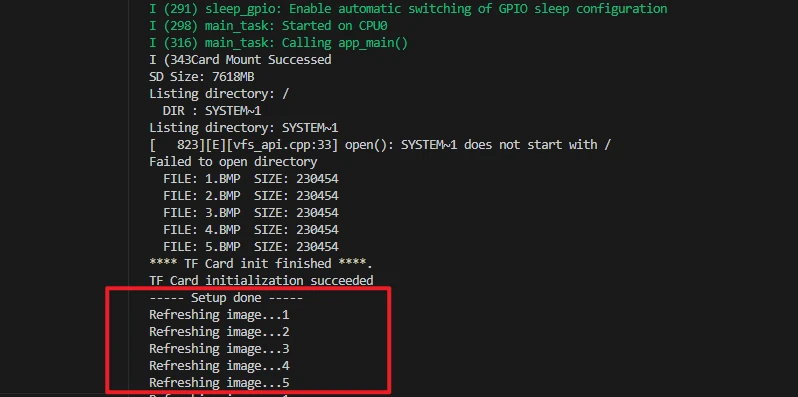
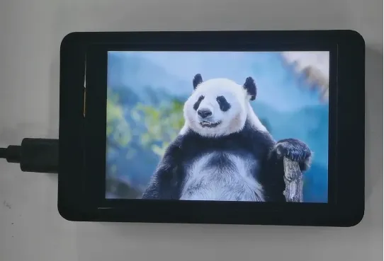
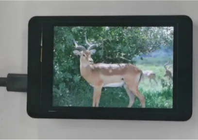
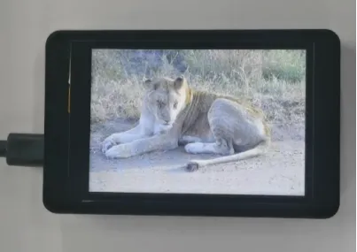
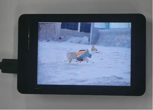
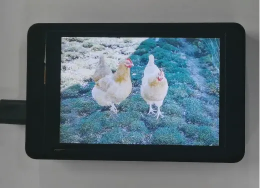
After the SD card is mounted successfully, the LCD displays the 5 BMP images from the SD card in a loop, each image staying on screen for about 5 seconds.
Note: The SD card experiment depends simultaneously on hardware contact, the file system, the file path, the image format, and the screen driver. When troubleshooting, it is recommended to check each item in order: whether the SD card is recognized by the computer → whether the files are in the root directory → whether the file names match → whether the images are 320x240/24-bit → whether the ESP-IDF project is complete.
8. Code Download
Code download link: Lesson05-SD_Images_24_28
Resource download: