3.5inch_Lesson06_nRF24L01_TX_RX
1. Course Introduction
In this lesson, two CrowPanel Advance development boards and two nRF24L01 modules are used to implement wireless text transmission and reception. The transmitter periodically sends text of the form Hello World I2:, and upon receiving it, the receiver prints it to the serial port and displays it on the LCD. Through this experiment, learners can verify whether the SPI pins, wireless address, channel, data rate, and the program roles on both ends are consistent.
2. Learning Objectives
- Be able to distinguish between the nRF24L01 transmitter and receiver projects.
- Be able to flash the two ESP32-S3 development boards separately and open two serial monitors to observe the logs.
- Be able to explain the relationship among
openWritingPipe(),openReadingPipe(), the address, and the channel. - Be able to troubleshoot the communication link based on symptoms such as successful transmission, failed reception, or no display on the LCD.
3. What You Need
- Hardware: two CrowPanel Advance ESP32-S3 development boards, two nRF24L01 modules.
- Cables: two USB data cables that support data transfer.
- Software: Arduino IDE, and the ESP32 Arduino development environment configured in Lesson 01.
- Dependencies: the RF24 library and the display driver files included in the project.
- Transmitter project:
lesson-06/WRITE/RF24_WRITE_3_5/RF24_WRITE_3_5.ino. - Receiver project:
lesson-06/READ/RF24_READ_3_5/RF24_READ_3_5.ino.
Code and Resource Download
Code download: - lesson-06
4. Software Operation Steps
4.1 Flashing the Transmitter
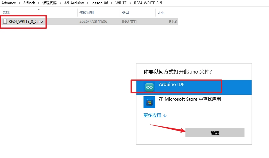
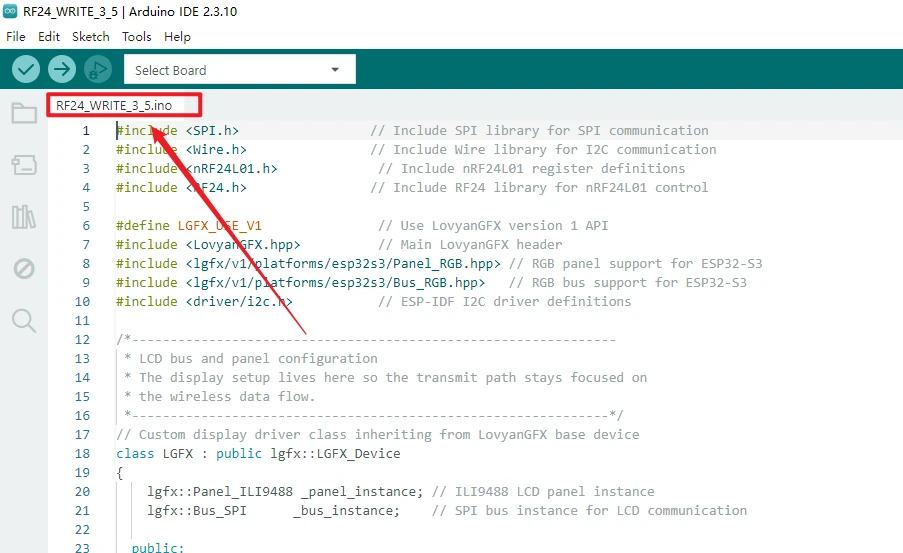
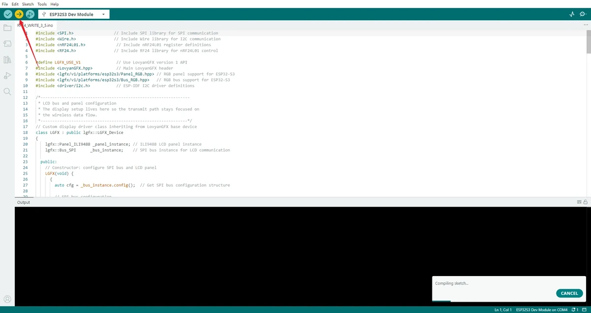
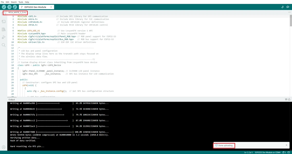
Open the transmitter project RF24_WRITE_3_5.ino using the Arduino IDE.
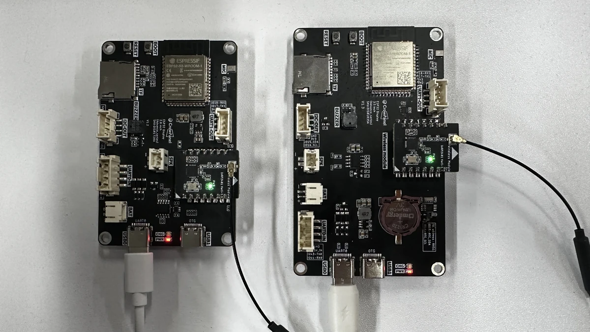
As required by the project, insert the nRF24L01 module into the W-M wireless module slot of the CrowPanel Advance development board. Use one board as the transmitter and the other as the receiver, and connect the boards to the computer using USB cables that support data transfer. (For this lesson, one CrowPanel Advance 3.5 inch board and one CrowPanel Advance 2.8 inch board are used.)
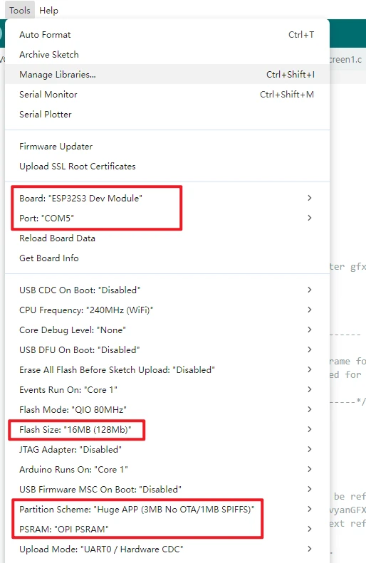
Configure the Arduino IDE. The commonly used settings are as follows:
-
Board:ESP32S3 Dev Module -
Port: select the serial port corresponding to the current board -
Flash Size:16MB (128Mb) -
PSRAM:OPI PSRAM -
Partition Scheme:Huge APP (3MB No OTA/1MB SPIFFS)
Click Upload to flash the transmitter program onto the first board.
4.2 Flashing the Receiver
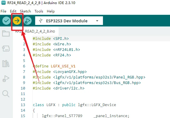
Use the other CrowPanel Advance 2.8 inch board as the receiver. Connect the 2.8 inch board to the computer and keep the same ESP32-S3 configuration as the transmitter.
Click Upload to compile and upload the receiver program. Open the receiver project RF24_READ_3_5.ino using the Arduino IDE.
4.3 Opening the Serial Monitor
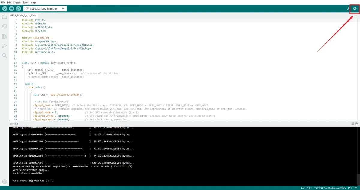
Open the two serial monitors separately and set the baud rate to 115200. Observe whether SENDING... or received content is output.
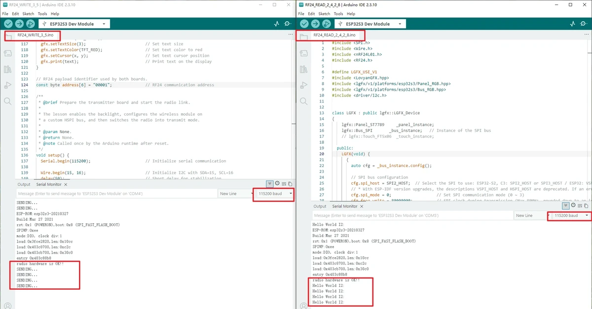
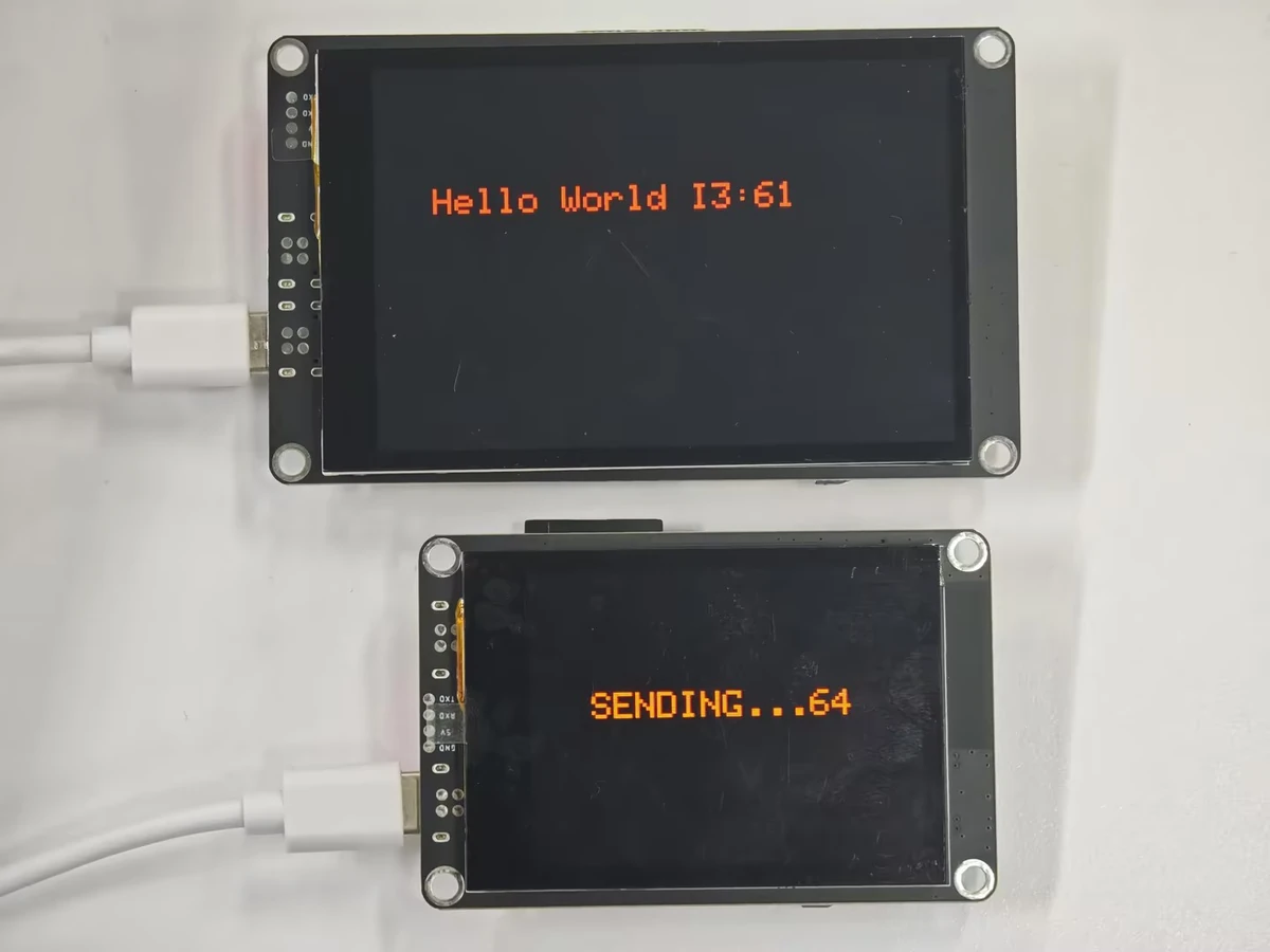
Observe whether the transmitter periodically outputs its sending status and whether the receiver receives the text and displays it on the LCD.
5. Hardware Connection Steps
- As required by the project, insert the nRF24L01 module into the W-M wireless module slot of the board.
- Prepare two boards, using one as the transmitter and the other as the receiver.
- Connect both boards with USB data cables to ensure a stable power supply.
- After the modules and boards are connected, observe the operating status of the transmitter and receiver separately.
6. Key Code Explanation
The radio object is responsible for controlling the nRF24L01 module. The CE and CSN pins must match the hardware wiring; otherwise, module initialization may fail.
The transmitter opens the writing pipe and exits listening mode. The address must match the receiver's reading pipe; otherwise, the transmitter may appear to send, but the receiver will not receive valid data.
The receiver opens the reading pipe and enters listening mode. If any of the address, channel, or data rate differs between the two ends, the receiver cannot receive data reliably.
The receiver only reads data when radio.available() is true. If the serial output never enters this branch, first check the power supply, wiring, wireless parameters, and whether both ends are running.
7. Experimental Results
After flashing is complete and the wireless modules are properly inserted, the transmitter's serial port will continuously output SENDING..., and the receiver's serial port and screen will display the received string content.
If no data is received, check the following items first:
- Whether the addresses of the two boards are consistent
- Whether the channel is consistent
- Whether the data rate is consistent
- Whether the nRF24L01 modules are properly inserted
- Whether both boards are properly powered
8. Code Download
Code path: lesson-06