3.5inch_Lesson07_LoRaWAN_AT_Command
1. Course Introduction
This lesson uses the CrowPanel Advance 3.5inch ESP32-S3 development board, the SX1262/LoRaWAN wireless module, and the ThinkNode-G1 gateway to complete LoRaWAN network join and data transmission. Learners first configure the G1 gateway to connect to the network and access TTN, then configure parameters such as DevEUI, JoinEUI/AppEUI, AppKey, and frequency band via serial AT commands, and finally perform the network join and uplink transmission.
The focus of this lesson is not simply flashing code, but completing the entire chain of "gateway, TTN platform, end-device parameters, AT commands, wireless transmission, and platform data."
2. Learning Objectives
- Be able to register the G1 gateway on the TTN platform, create an Application, and register an OTAA end device.
- Be able to use SSCOM or similar serial tools to send AT commands and configure DevEUI, JoinEUI/AppEUI, AppKey, frequency band, and join method.
- Be able to explain the relationship among AT command parsing, the command table, and callback functions.
- Be able to determine whether the network join and transmission succeeded based on RadioLib return codes, serial logs, and TTN Live data.
3. Preparation
- Hardware: CrowPanel Advance 3.5inch ESP32-S3 development board, SX1262/LoRaWAN wireless module, antenna.
- Gateway: ThinkNode-G1 LoRaWAN gateway.
- Cables: Type-C USB data cable that supports data transfer.
- Software: Arduino IDE and the ESP32 Arduino development environment, SSCOM serial debugging tool.
- Platform account: The Things Network account.
- Project:
sendATcommands_3.5.ino. - Tool:
lesson-07/tool/SSCOM.zip.
Note: The LoRaWAN frequency band must match the gateway, the TTN Frequency plan, and the end-device AT commands at the same time. When the frequency bands are inconsistent, the serial port may show a transmission action, but the platform will not receive any data.
Code and Resource Download
Code download: - lesson-07
4. Software Operation Steps
4.1 Overall Experiment Flow
The software operations in this lesson proceed in the order of "open the project and flash the program -> configure the G1 gateway and TTN platform -> send AT commands using SSCOM -> view data on TTN."
- Open the 3.5inch LoRaWAN AT project using Arduino IDE.
- Configure the board, port, Flash Size, PSRAM, and Partition Scheme as described in Lesson01.
- Compile and flash
sendATcommands_3.5.ino. - Configure the ThinkNode-G1 gateway networking method and Packet Forwarder.
- Register the G1 gateway on the TTN platform, and create an Application and an End device.
- Use SSCOM to send AT commands, configure the node parameters, perform the network join, and send data.
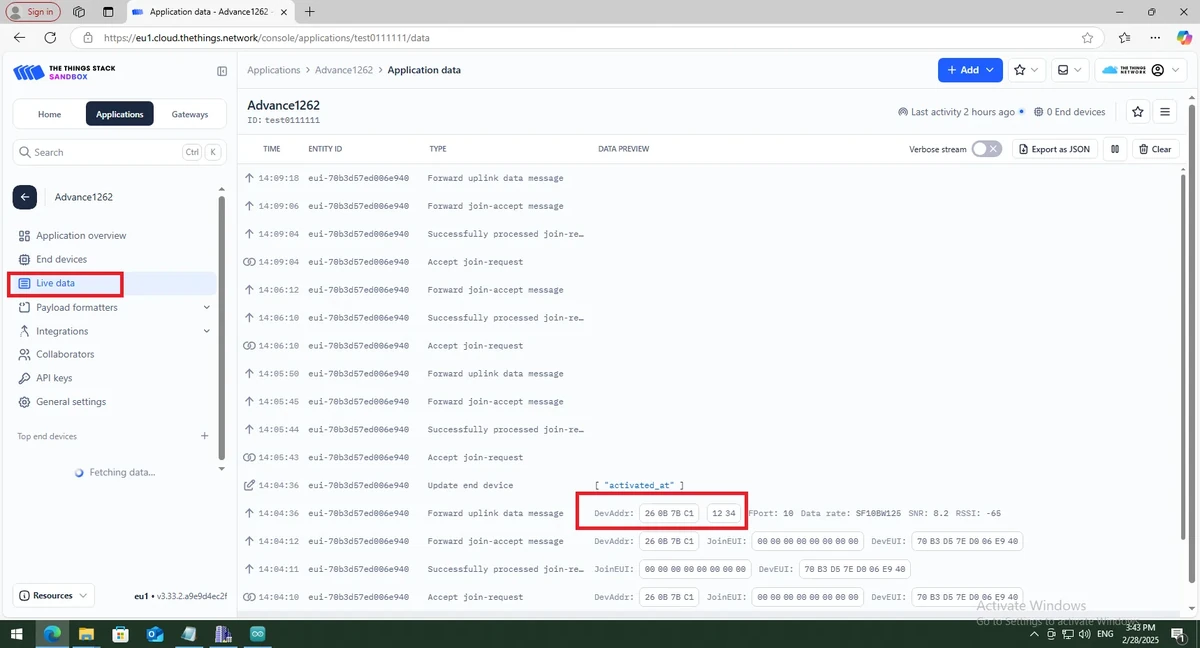
- View the data uploaded by the node on the TTN Live data page.
4.2 Open and Flash the 3.5inch Project
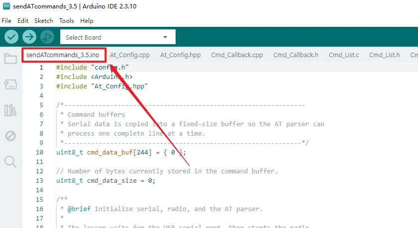
Open this lesson's project using Arduino IDE: 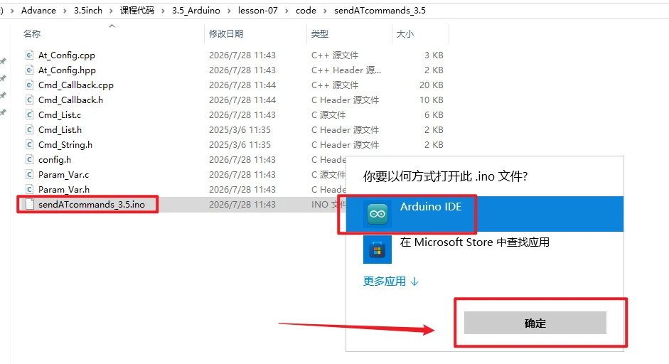
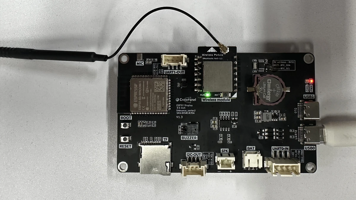
Insert the wireless module into the CrowPanel Advance 3.5inch development board and install the antenna. Connect the development board to the computer using a Type-C USB cable that supports data transfer.
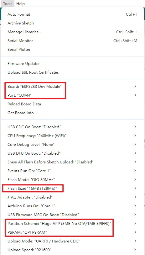
In the Tools menu of Arduino IDE, confirm the following parameters:
Board: ESP32S3 Dev Module
Port: select the serial port corresponding to the current board
Flash Size: 16MB (128Mb)
PSRAM: OPI PSRAM
Partition Scheme: Huge APP (3MB No OTA/1MB SPIFFS)
Serial Monitor baud: 115200
Click Upload to compile and wait for the upload to complete. If it hangs at Connecting..., check for port occupation and use BOOT/RESET download mode as required by the board. 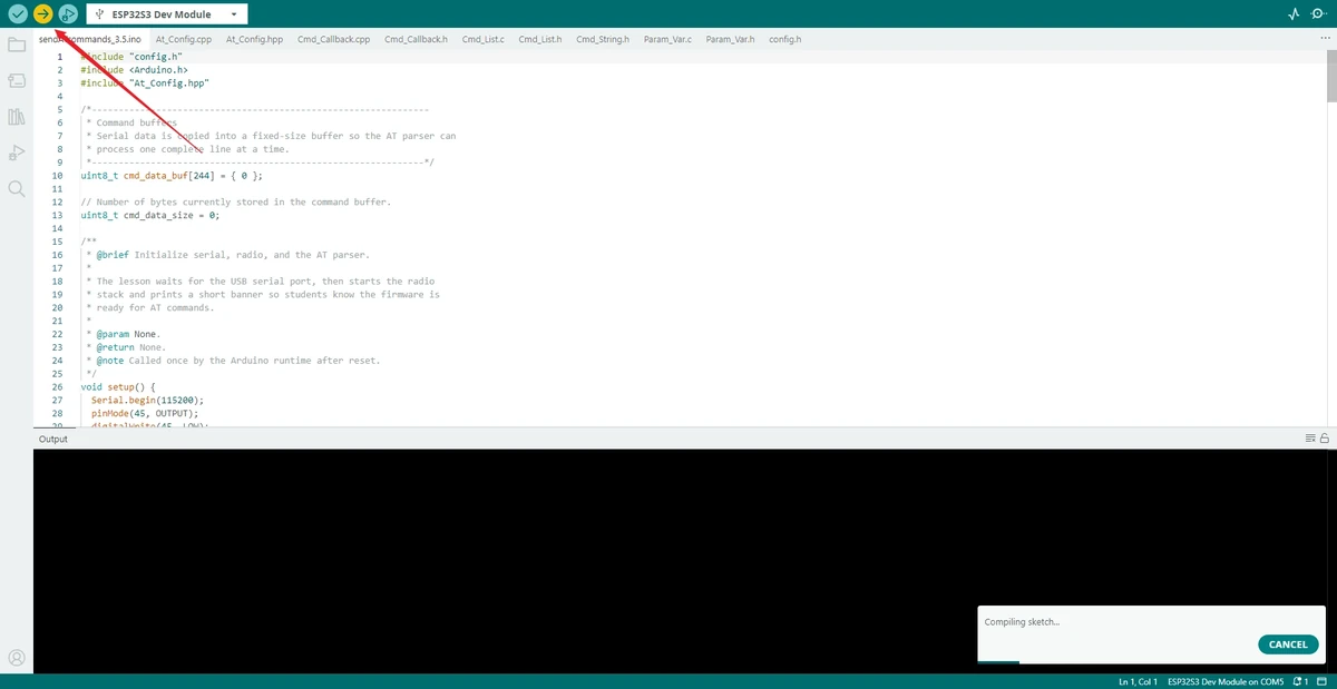
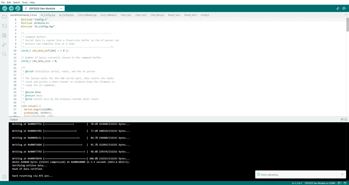
Note: If you find that the board behaves abnormally during the flashing stage, remove the wireless module first and then upload the program. After confirming that the program is written successfully, plug the module back in.
After the program is flashed, this lesson does not use the Arduino IDE Serial Monitor as the primary input tool. Instead, SSCOM is used to send AT commands. The SSCOM baud rate should also be set to 115200.
4.3 G1 Gateway Configuration, TTN Registration, End Device Creation, and SSCOM AT Commands
4.3.1 G1 Gateway Network Configuration
The G1 gateway supports three networking methods: Ethernet, Wi-Fi, and 4G cellular network, of which 4G is only available for the 4G version. This lesson uses Wi-Fi as the networking method.
Press and hold the gateway button for about 5 seconds until the top indicator light slowly blinks blue, and the device enters configuration mode.
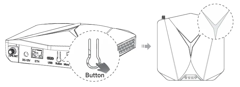
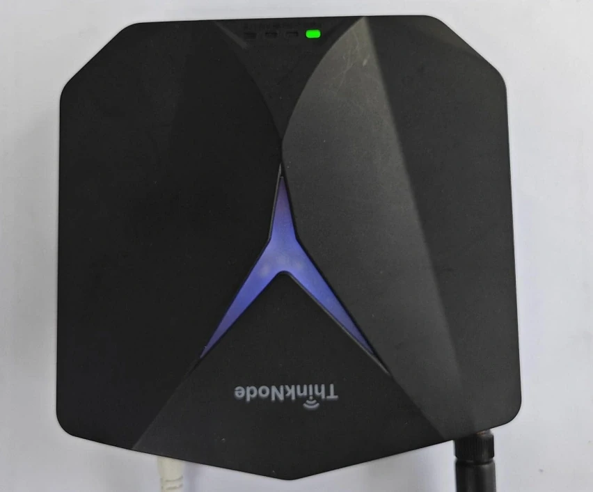
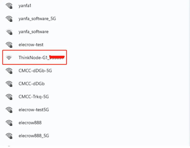
Connect to the AP hotspot. The hotspot name is ThinkNode-G1_XXXXXX, where XXXXXX is the 6-digit MAC address. This hotspot is open by default and can be connected directly without a password.
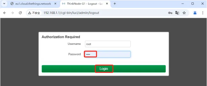
Enter 192.168.1.1 in the browser to access the local console. Enter root for both the username and password.
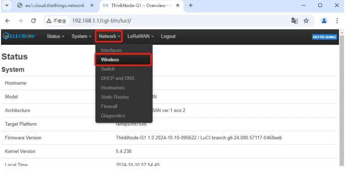
After logging into Luci, click Network > Wireless.
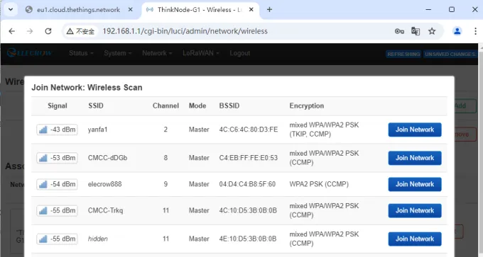
Click Scan to scan for nearby Wi-Fi networks.
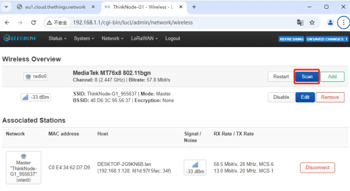
Select the Wi-Fi network to connect to and click Join Network.
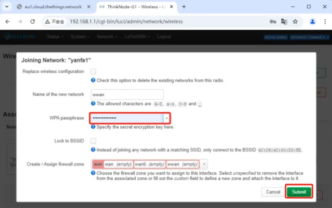
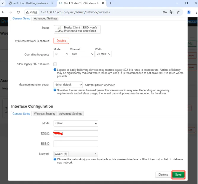
Enter the Wi-Fi password, click Submit, and then save the settings.
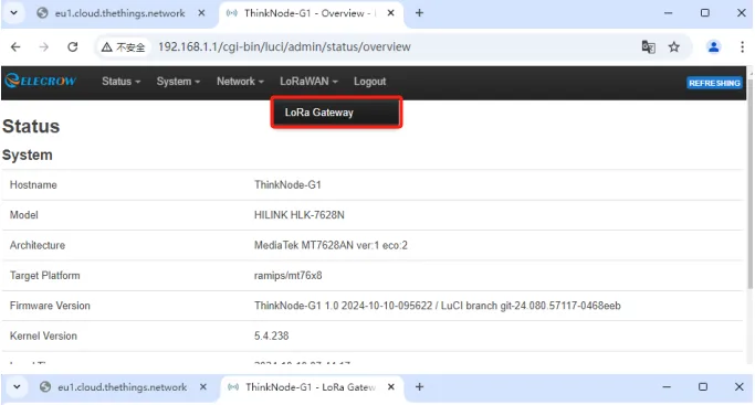
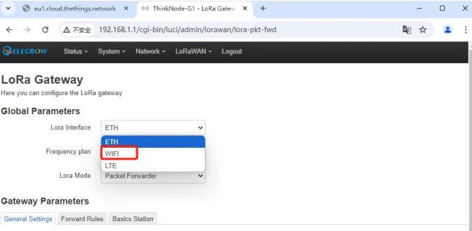
On the Luci page, click LoRaWAN, go to the LoRa Gateway page, and set the network configuration mode to WiFi.
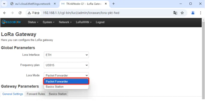
Set the gateway working mode to Packet Forwarder.
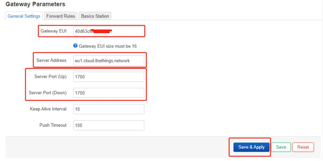
Configure the Packet Forwarder. Gateway EUI automatically obtains the EUI of the currently connected gateway; enter the The Things Stack deployment address in Server address; Server Ports (Up/Down) is generally set to 1700.
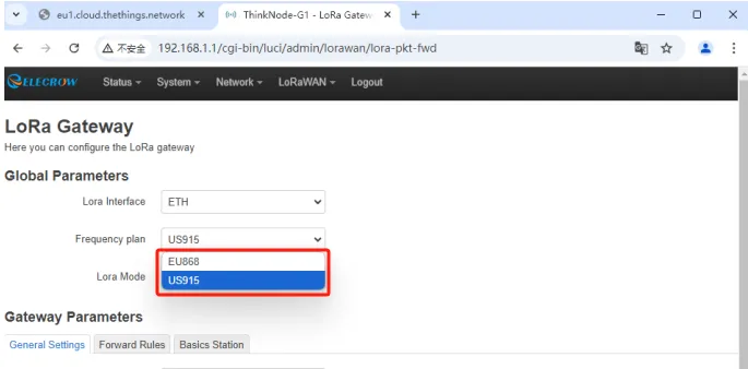
Configure Region and Frequency plans, and click Save & Apply. The frequency band here must be consistent with the TTN platform and the end-device AT commands.

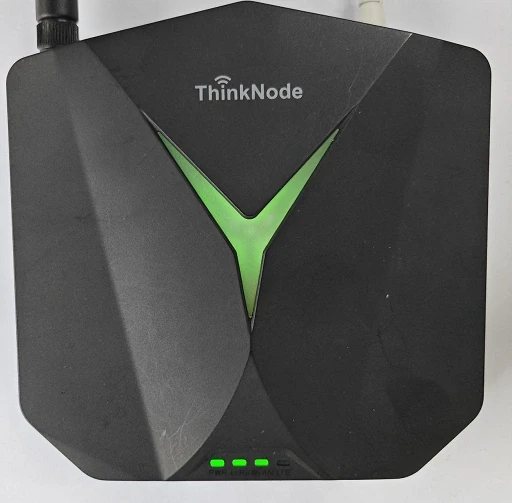
Double-click the gateway reset button and wait for the device to restart. If the gateway successfully connects to Wi-Fi, the WLAN green indicator light stays solid, and the top indicator light also remains green.
4.3.2 Register the Gateway on the TTN Platform
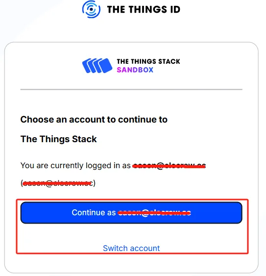
Open The Things Network and log in to the TTN account.
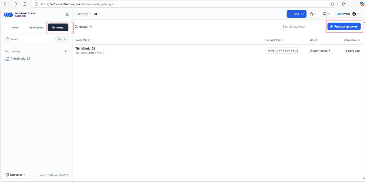
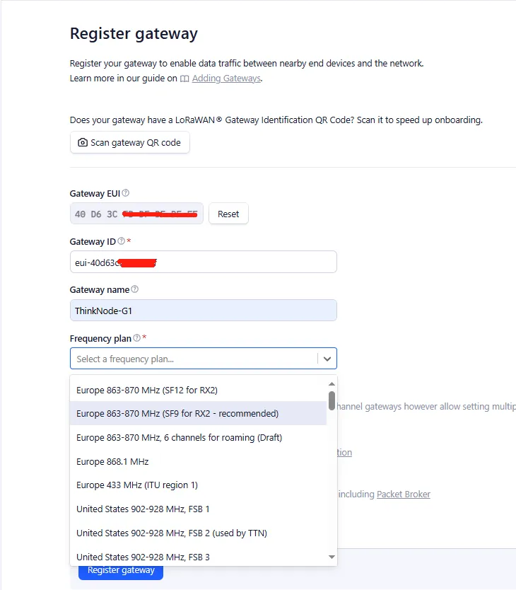
Register the gateway, fill in the EUI, and click Confirm.
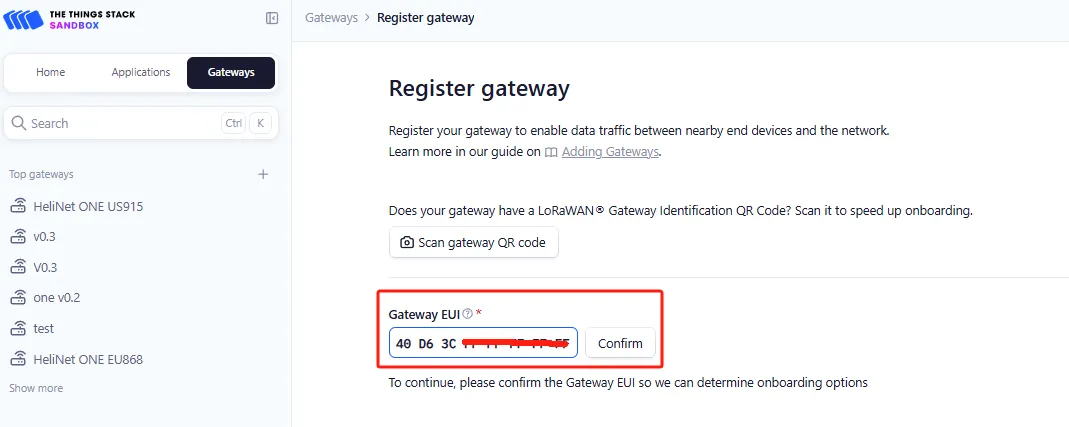
Gateway ID is usually written as eui-gatewayEUI and may only use lowercase letters, numbers, and hyphens.
Fill in the Gateway Name and select the Frequency Plan that matches the gateway version.
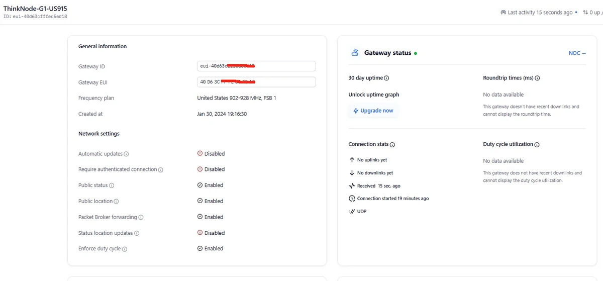
After successful registration, you can view the gateway status on the Overview page.
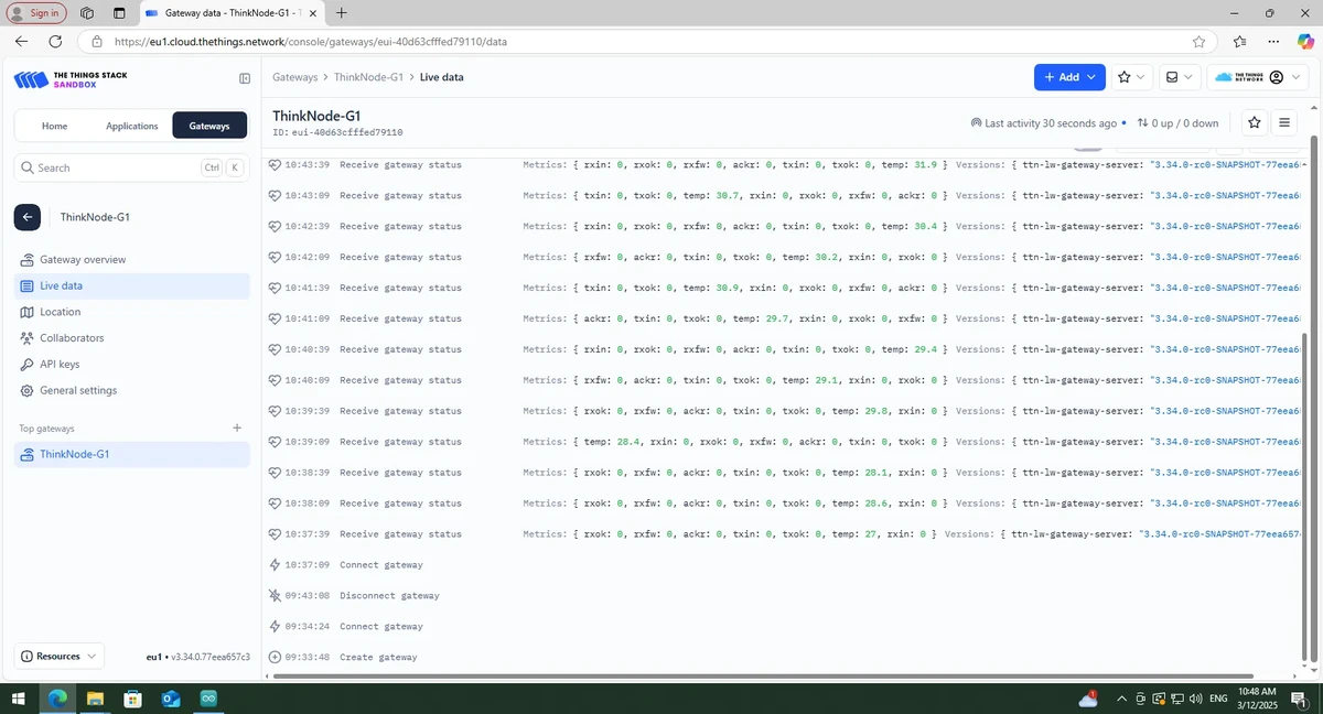
Double-click the gateway settings button and wait for the restart. The gateway connects to TTN in Packet Forwarder mode.
4.3.3 Create the TTN Node Application
Click Applications in the TTN console.
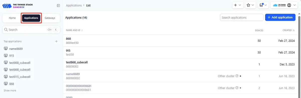
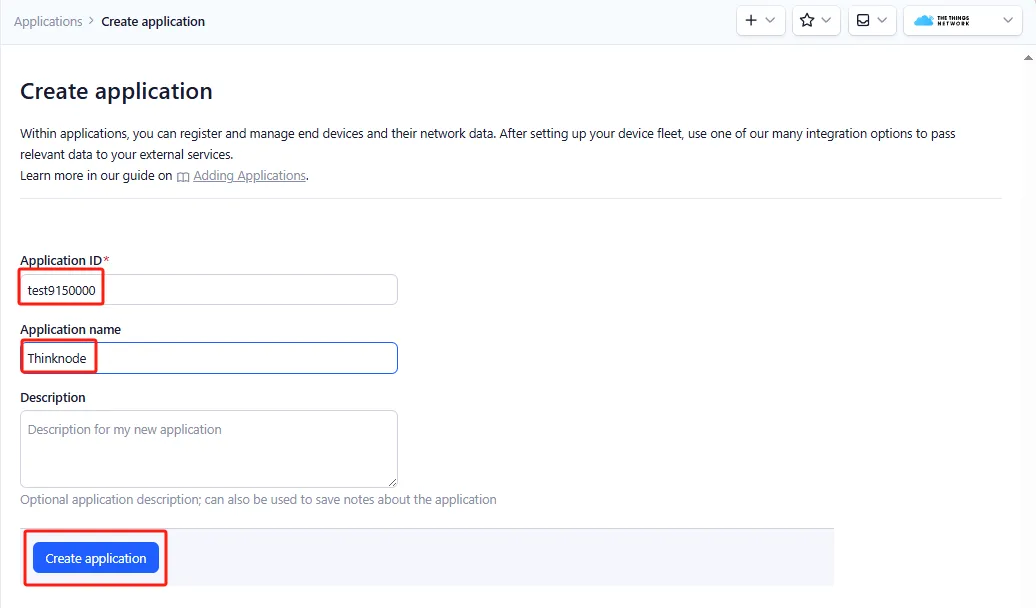
Click Add application, fill in the Application ID and Application name, then click Create application.
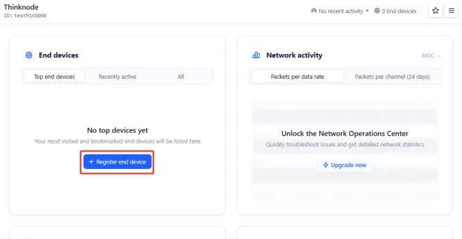
On the application Overview page, click Register end device.
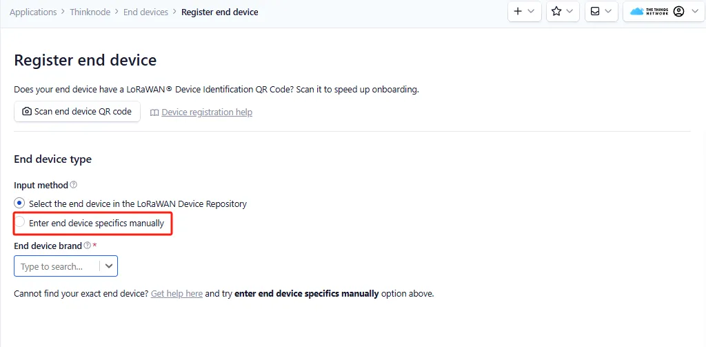
Select Enter end device specifics manually.
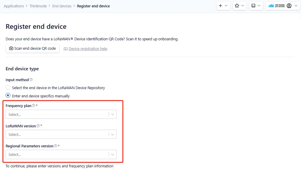
Set the Frequency plan, LoRaWAN version, Regional Parameters version, and JoinEUI.
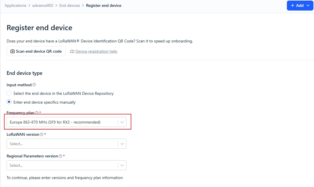
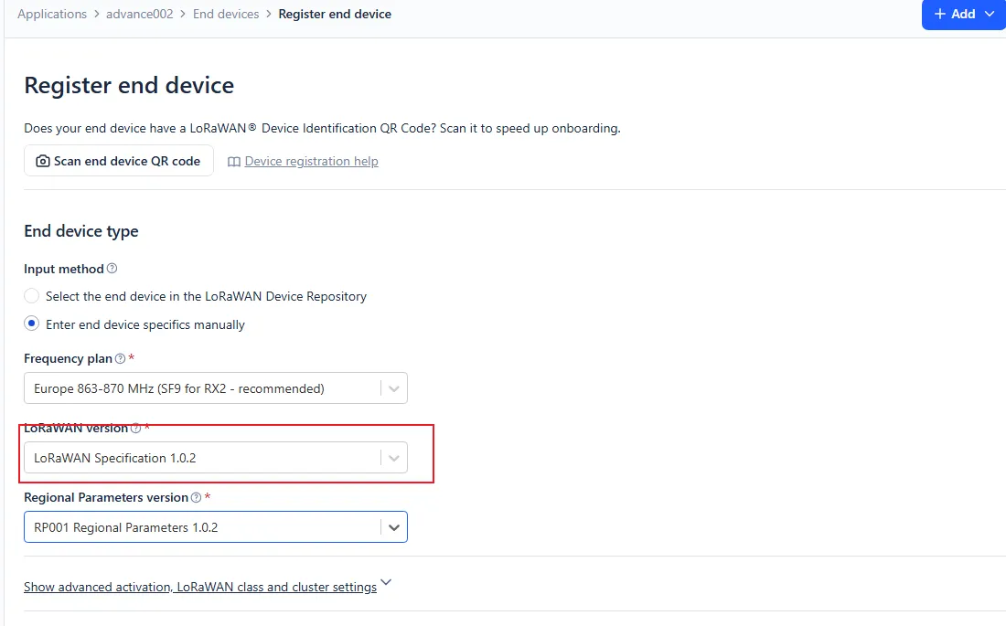
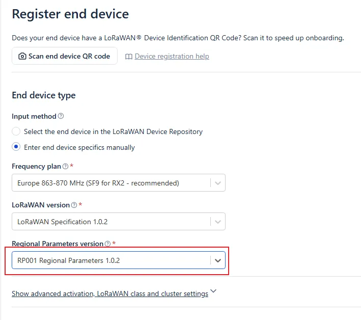
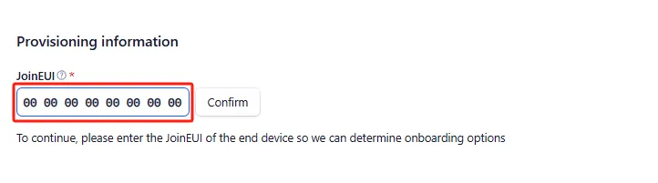
Expand the advanced settings, configure it to OTAA mode, and click Confirm.
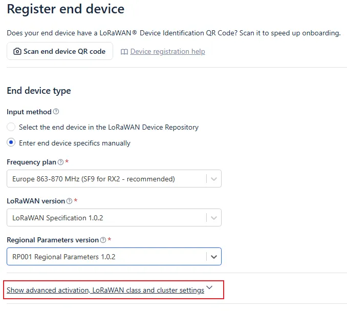
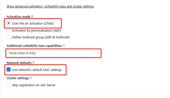
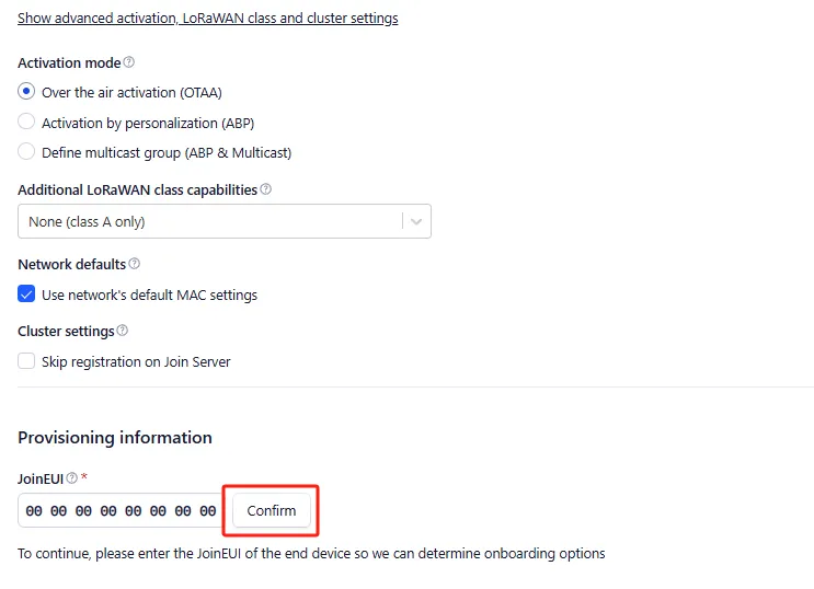
Click Generate to generate the DevEUI and AppKey, fill in the End device ID, then click Register end device.
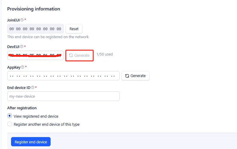
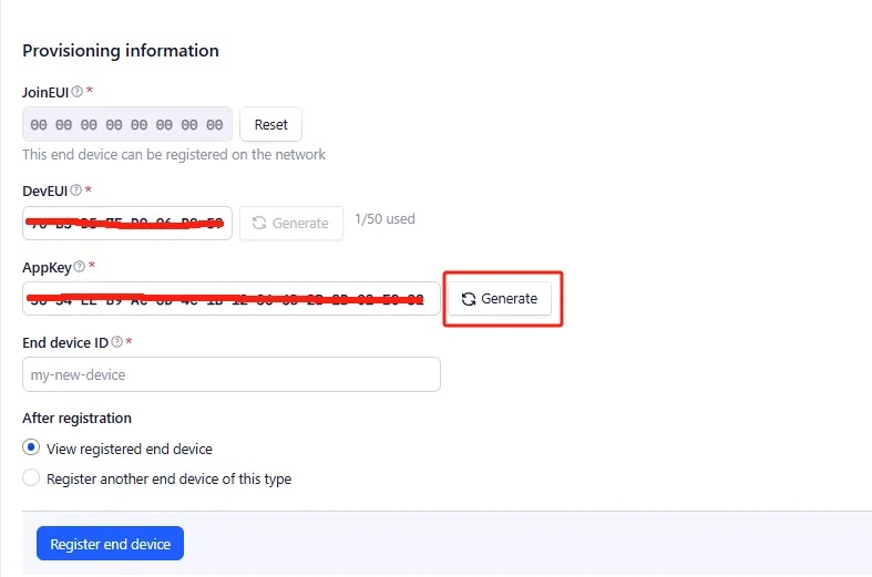
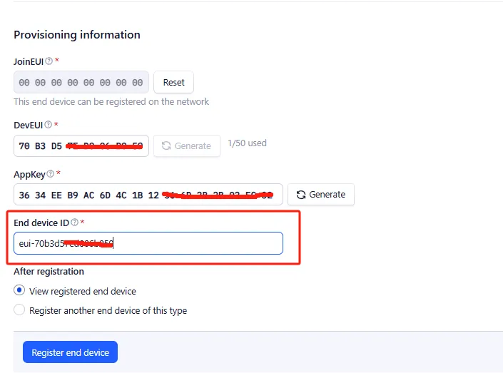
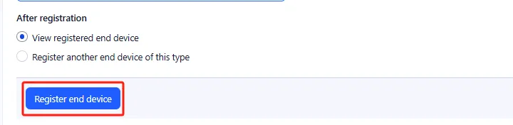
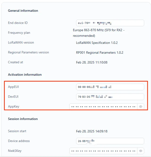
After registration, save the DevEUI, JoinEUI/AppEUI, and AppKey from the Activation information.
4.3.4 Set Up Join Nonces Reset
To make it easy to repeatedly test the network join during experiments, you can enable Resets join nonces in the TTN device settings.
Go to Application > Application Name.
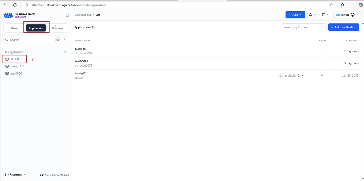
Click the node name to enter Settings.
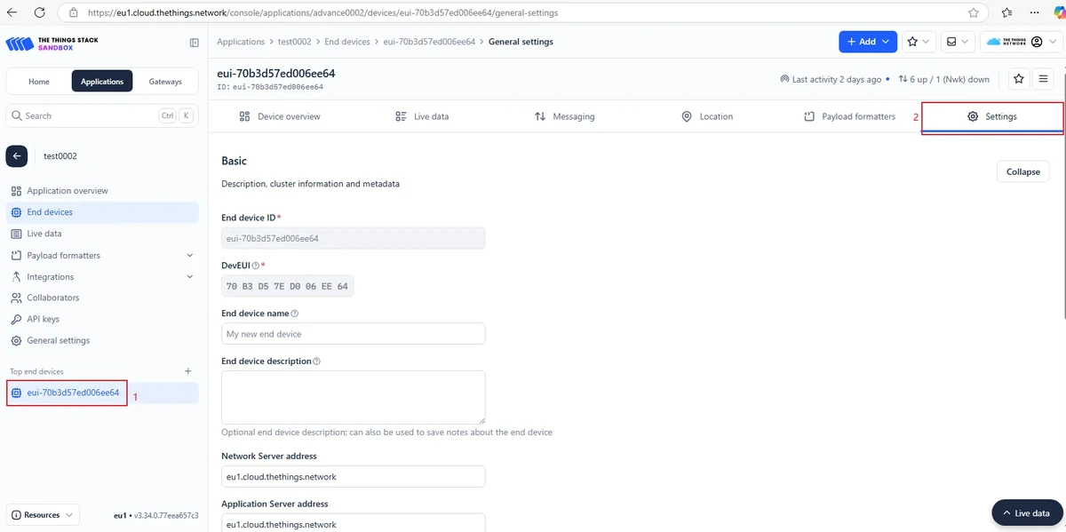
Scroll to the bottom of the page and open Join Settings.
Remember to click "Save changes" to save your modifications.

Enable Resets join nonces.
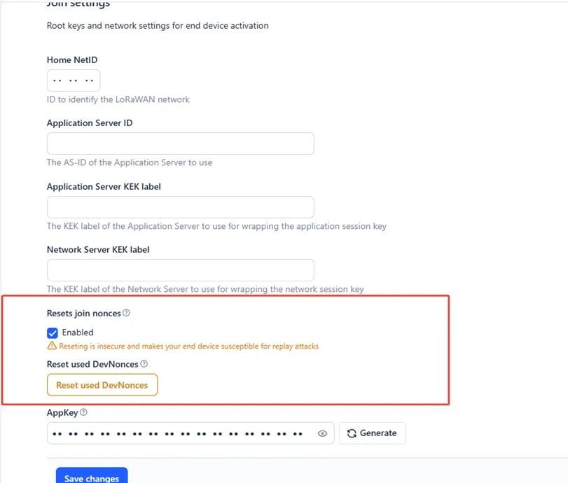
4.3.5 Send AT Commands Using SSCOM
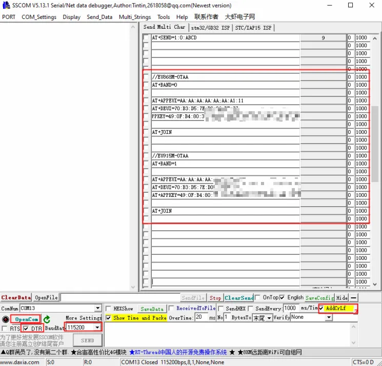
Open the SSCOM serial tool, select the USB COM port recognized by the computer, then click EXT.
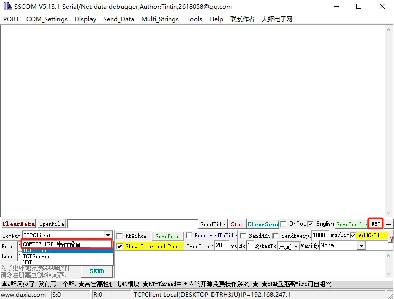
Set the serial parameters to 115200, check the carriage-return-line-feed option, and when opening the serial port, only check DTR.
Send the following AT commands to configure the node parameters in order:
AT+BAND=0
AT+DEUI=70:B3:D5:7E:D0:06:****
AT+APPEUI=AA:AA:AA:AA:AA:AA:****
AT+APPKEY=49:0F:B4:80:37:F0:5E:6C:5C:B3:24:F5:B5:78:****
Replace DevEUI, AppEUI, and AppKey with the actual values from the TTN page.
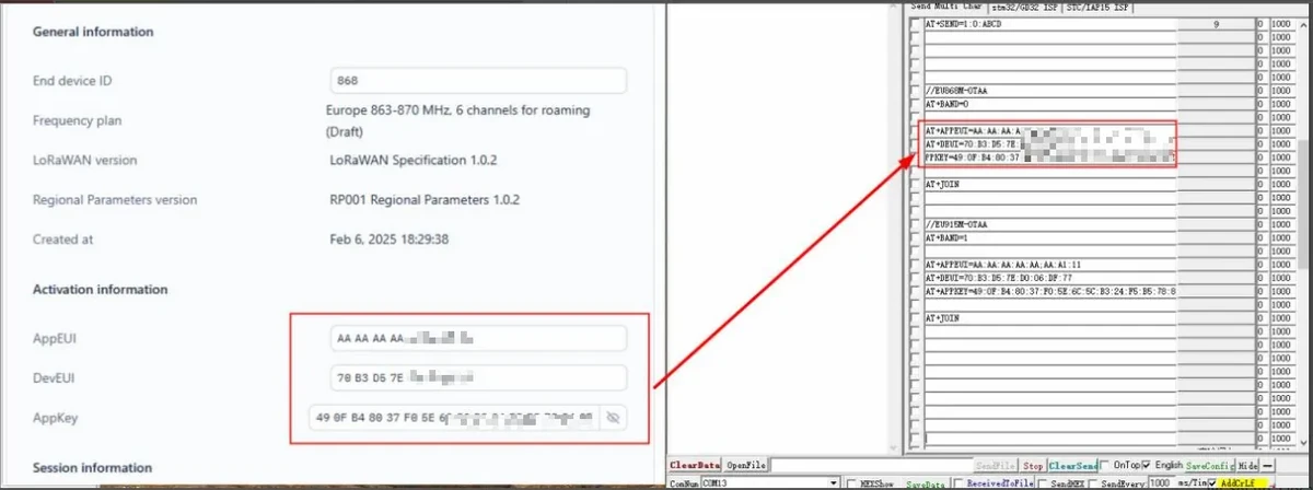
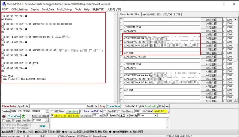
Send the network join command AT+JOIN and wait for the node to successfully join the network.
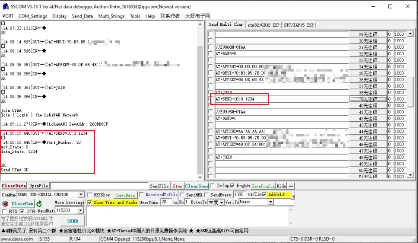
Send the data AT+SEND=10:0:1234, then check the data reported by the node on TTN's Applications > Live data page.
5. Hardware Operation Steps
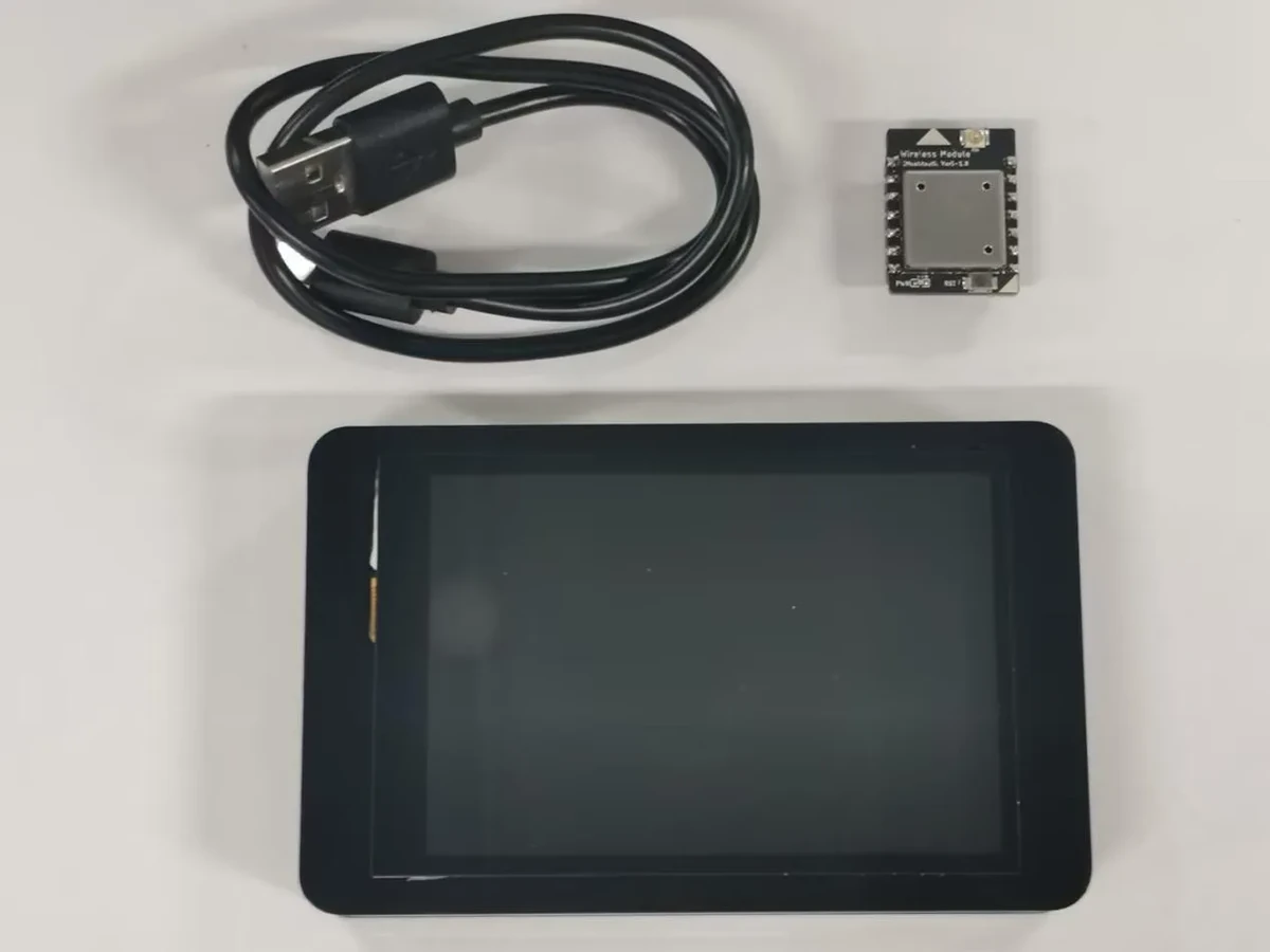
Insert the Wireless module-Meshtastic block into the W-M wireless module slot on the development board, and connect the CrowPanel Advance development board using a USB data cable.
6. Key Code Explanation
radio defines how the SX1262 module is connected, and node defines the LoRaWAN node object. The frequency band and subBand must be consistent with the gateway, the TTN platform, and the AT commands.
The command table binds command strings to callback functions. When adding a new command, you need to define the string and the callback function, and then register it in the table.
if (at_config.receiveSerialCmd(cmd_data_buf, &cmd_data_size)) {
  at_config.parseCmd((char *)cmd_data_buf, cmd_data_size);
}
The main loop first receives the serial command and then passes it to the parser. If the serial port does not respond, first check the baud rate, the carriage return/line feed format, and the SSCOM sending method.
AT commands do not perform the network join directly within the parser; instead, they set a flag, and the main loop then executes the actual wireless operation. This prevents the serial parsing logic from being entangled with the time-consuming network join operation.
7. Experimental Observations
After the end device is configured successfully, sending AT+JOIN in SSCOM will display network join related logs; after sending AT+SEND=10:0:1234, the data reported by the node can be viewed on TTN's Applications > Live data page.
If the network join fails, first check the following items:
- Whether the frequency band is consistent across the G1 gateway, the TTN gateway, the TTN end device, and the AT commands.
- Whether the
Gateway EUIis correctly entered on TTN. - Whether
DevEUI,JoinEUI/AppEUI, andAppKeyexactly match those on the TTN end device page. - Whether the G1 gateway is connected to the network and properly linked to TTN.
- Whether SSCOM is using the
115200baud rate and appending a carriage return/line feed when sending. - Whether the wireless module is correctly seated in the development board, and whether the development board port and hardware connections were completed as described in Lesson 1.
8. Code Download
Code download path: lesson-07