3.5inch_Lesson09_Zigbee_Light_Control
1. Course Introduction
In this lesson, the ESP32-H2 wireless module runs two Zigbee example programs: one acts as an end-device light, and the other acts as a switch coordinator. Learners can use the coordinator's pushbutton to control the on/off state of the remote light, and observe pairing, binding, and state-change information in the serial output. The lesson also provides a zigbee_3.5.ino serial forwarding example, which lets you view the H2 module's output through the 3.5-inch CrowPanel main controller.
This lesson is well suited for reviewing "role division": one side is responsible for joining the network and responding to commands as the light endpoint, while the other side builds the network, binds devices, and sends on/off commands.
2. Learning Objectives
- Be able to distinguish the roles of a Zigbee end device versus a coordinator/router.
- Be able to select the correct Zigbee mode and partition scheme for the ESP32-H2 wireless module.
- Be able to flash the
Zigbee_On_Off_Light,Zigbee_On_Off_Switch, andzigbee_3.5projects respectively. - Be able to determine from the serial output whether the network is established, binding is successful, and the light state has toggled.
3. What You Need to Prepare
- Hardware: two CrowPanel Advance development boards and two ESP32-H2 wireless modules.
- Cables: Type-C USB data cables that support data transfer.
- Software: Arduino IDE with the ESP32 Arduino development environment that has Zigbee support installed.
- Board package:
esp32 by Espressif Systems, ideally kept consistent with the course environment. - Official example:
File > Examples > Zigbee > Zigbee_On_Off_Light. - Official example:
File > Examples > Zigbee > Zigbee_On_Off_Switch. - Local project:
Zigbee_On_Off_Light.ino. - Local project:
Zigbee_On_Off_Switch.ino. - Serial forwarding project:
zigbee_3.5.ino.
Note: The ESP32-H2 wireless module has a built-in Type-C interface and can be connected directly to a computer to flash the Zigbee example code. The CrowPanel main controller and the H2 wireless module are two different flashing targets, so do not mix up the Tools menu configurations.
Code and Resource Download
Code download: - lesson-09/zigbee_3.5
4. Software Operation Steps
4.1 Select a Build Method
This lesson offers two ways to prepare the code:
Use the Zigbee examples that ship with the Arduino IDE. Open File > Examples > Zigbee and select Zigbee_On_Off_Light and Zigbee_On_Off_Switch.
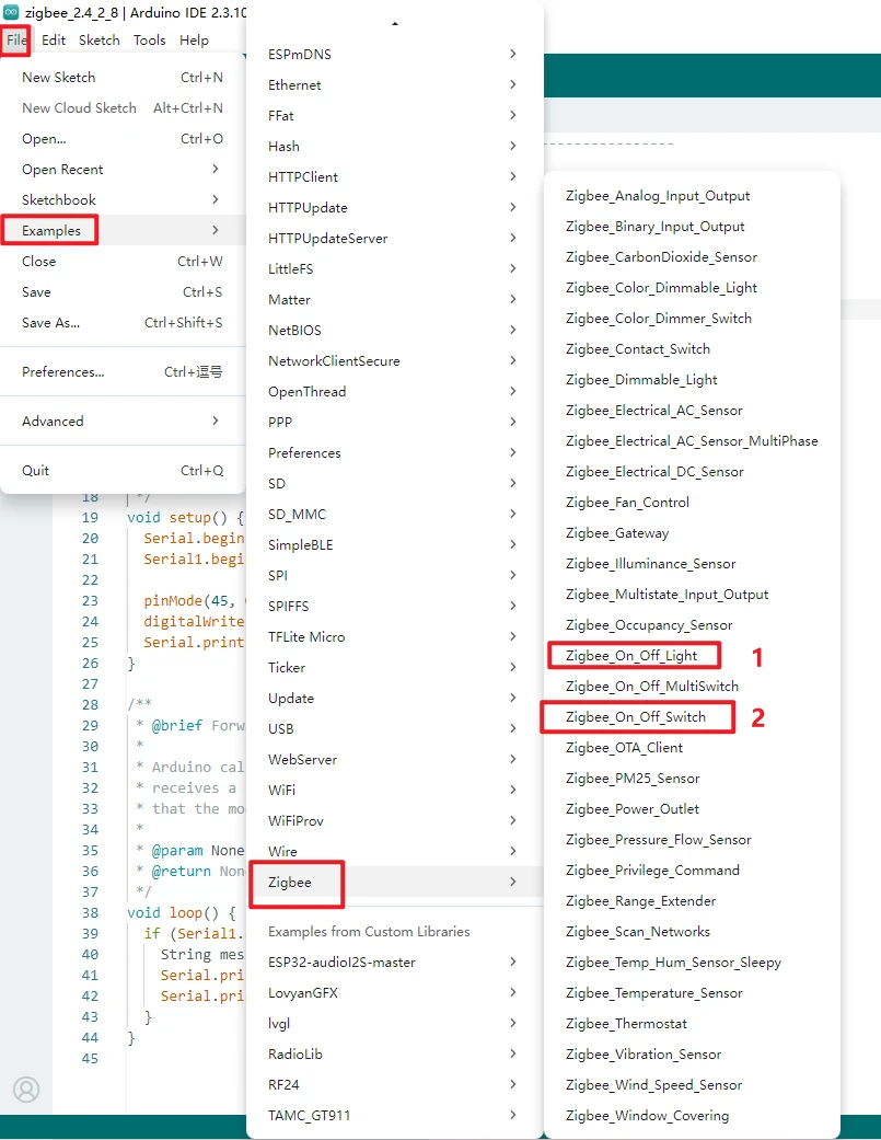
Use the local course code. Open each of the following separately:
3.5_Arduino/lesson-09/Zigbee_On_Off_Light/Zigbee_On_Off_Light.ino
3.5_Arduino/lesson-09/Zigbee_On_Off_Switch/Zigbee_On_Off_Switch.ino
4.2 Flash the ESP32-H2 Switch Coordinator
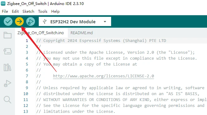
Open the switch coordinator project Zigbee_On_Off_Switch.ino in the Arduino IDE.
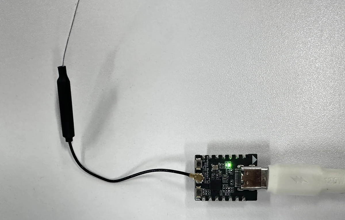
Connect the first ESP32-H2 wireless module to your computer using a Type-C USB cable that supports data transfer. The H2 wireless module can be flashed by connecting directly to the computer without going through the CrowPanel.
Complete the switch coordinator configuration in the Tools menu in order:
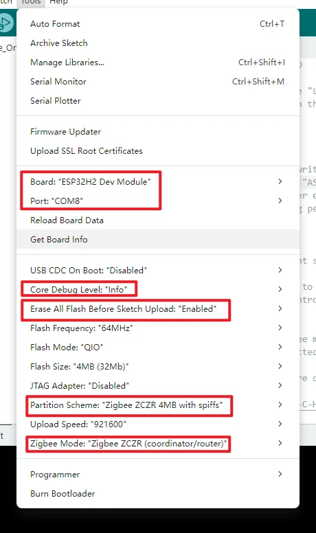
Board: ESP32H2 Dev Module
Core Debug Level: Info
Erase All Flash Before Sketch Upload: Enabled
Flash Size: 4MB (32Mb)
Partition Scheme: Zigbee ZCZR 4MB with spiffs
Zigbee Mode: Zigbee ZCZR (coordinator/router)
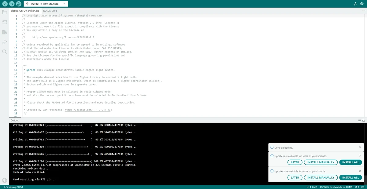
Click Upload to compile and wait for the upload to finish. If it gets stuck at Connecting..., check the Type-C data cable, port occupancy, and put the module into download mode as required.
4.3 Flash the ESP32-H2 End-Device Light
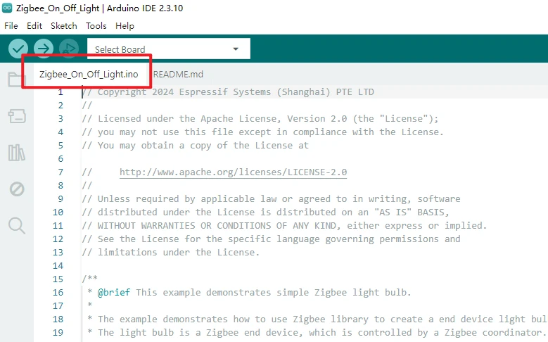
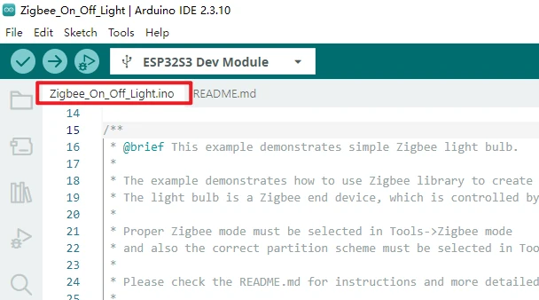
Open the end-device light project Zigbee_On_Off_Light.ino in the Arduino IDE.
Connect the second ESP32-H2 wireless module to your computer using a Type-C USB cable, or switch to the serial port corresponding to the other H2 module.
Complete the end-device light configuration in the Tools menu in order:
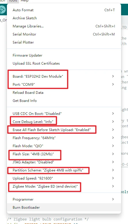
Board: ESP32H2 Dev Module
Core Debug Level: Info
Erase All Flash Before Sketch Upload: Enabled
Flash Size: 4MB (32Mb)
Partition Scheme: Zigbee 4MB with spiffs
Zigbee Mode: Zigbee ED (end device)
Click Upload to compile and wait for the upload to finish.
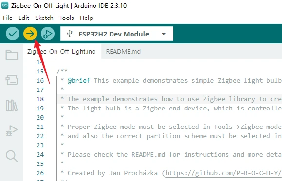
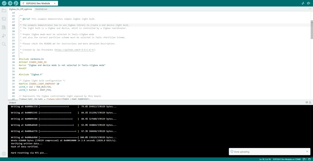
4.4 Flash the 3.5-inch CrowPanel Serial Forwarding Example
If you need to view the H2 module's output in the CrowPanel main controller's serial port, open the zigbee_3.5.ino provided in this lesson. This example forwards the data received on the wireless module's serial port to the Arduino IDE Serial Monitor.
Open the CrowPanel serial forwarding project zigbee_3.5.ino in the Arduino IDE.
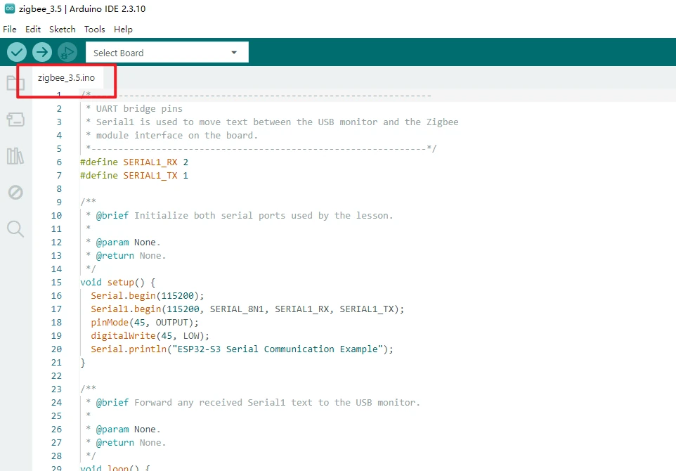
Connect the CrowPanel Advance 3.5-inch development board to your computer using a Type-C USB cable that supports data transfer.
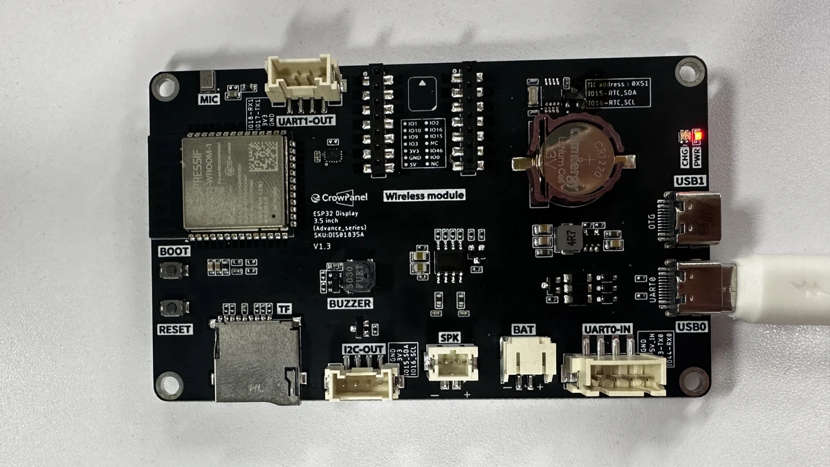
Complete the CrowPanel main controller configuration in the Tools menu in order:
-
Board:ESP32S3 Dev Module -
Port: select the serial port corresponding to the current development board -
Flash Size:16MB (128Mb) -
PSRAM:OPI PSRAM -
Partition Scheme:Huge APP (3MB No OTA/1MB SPIFFS)
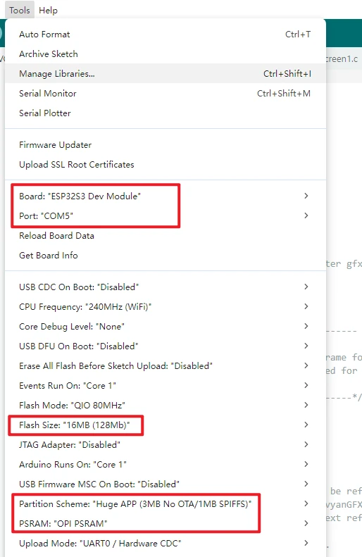
Note: The CrowPanel main controller uses the ESP32S3 Dev Module configuration; the H2 wireless module uses the ESP32H2 Dev Module configuration. These are two different firmware flashing targets, so do not apply the H2's ZigBee Mode configuration to the CrowPanel main controller project.
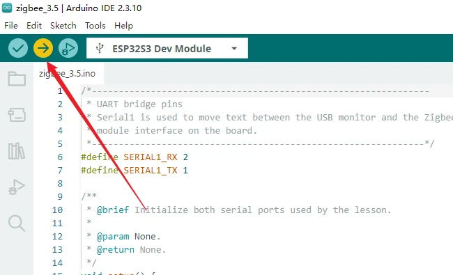
Click Upload to compile and wait for the upload to finish. Flash the other CrowPanel Advance 2.8-inch development board with the serial forwarding project using the same steps.
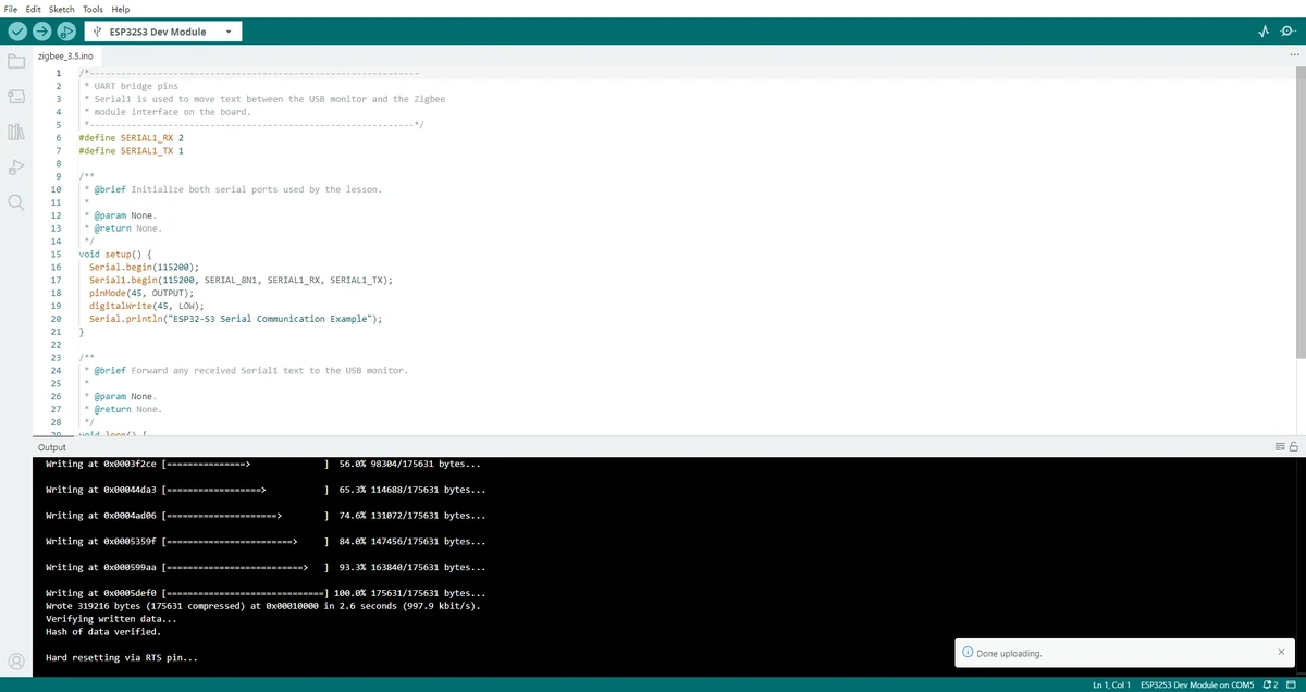
Insert the flashed ESP32-H2 wireless modules into the two CrowPanel Advance development boards of different sizes. (You may use CrowPanel Advance development boards of different sizes to flash the corresponding code.)
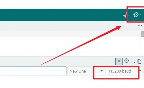
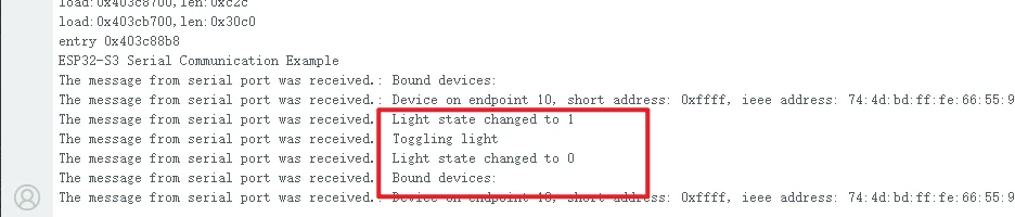
Open the Serial Monitor in the top-right corner, set the baud rate to 115200, and press the RST button on the wireless module to confirm that you can see the bound-device and light-state-change information forwarded by the H2 module.
5. Hardware Operation Steps
Install the H2 wireless module with the switch coordinator program flashed onto one CrowPanel Advance 3.5-inch development board.
Install the H2 wireless module with the end-device light program flashed onto the other CrowPanel Advance 2.8-inch development board.
Connect both development boards to your computer using USB cables that support data transfer, or power them separately with a stable power supply.
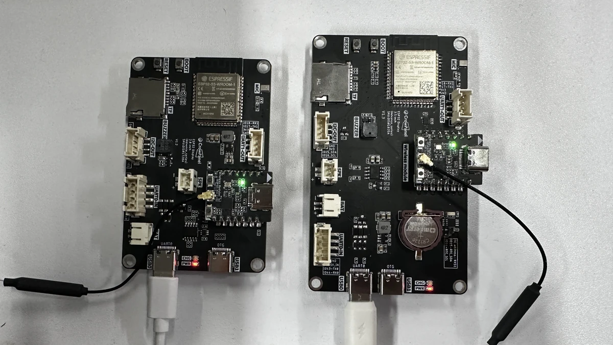
After both boards are powered on, wait for the Zigbee network to be established and binding to complete.
Press the BOOT button on the switch coordinator side and observe whether the end-device light state toggles.
If you see messages such as Bound devices, Device on endpoint, and Light state changed to 0/1 in the serial output, it means the binding and control flow is working properly.
If you need to re-pair, you can first erase the Flash and re-flash both ends with the examples, then let the coordinator reopen the network.
6. Key Code Explanation
ZigbeeLight zbLight = ZigbeeLight(ZIGBEE_LIGHT_ENDPOINT);
ZigbeeSwitch zbSwitch = ZigbeeSwitch(SWITCH_ENDPOINT_NUMBER);
These two objects represent the light endpoint and the coordinator-side Zigbee device respectively. They determine each device's role in the network, as well as what capabilities it can later expose to the peer.
These two statements tie the network state to the on-board behavior. When the light state changes, the LED is driven directly; when the coordinator receives a state report, it prints a log directly. This lets learners see both the "network action" and the "hardware action" at the same time.
In the CrowPanel serial forwarding example, the main controller's USB serial port is used for computer debugging, while Serial1 is used to receive the wireless module's output. This way, even though the H2 module handles Zigbee communication on its own, you can still observe the experiment information through the CrowPanel's Serial Monitor.
7. Experimental Observations
After the light endpoint is powered on, it waits for Zigbee network connection; once the coordinator side completes binding, the serial output will display the bound-device information. When the coordinator button is pressed, the remote light toggles on or off accordingly, and the serial output shows Light state changed to 0 or Light state changed to 1. If you want to run the experiment again, erase the Flash and re-flash both ends with the examples.
8. Code Download
Code path: lesson-09/zigbee_3.5