3.5inch_Lesson10_Microphone_Record_Playback
1. Course Introduction
This lesson uses the ESP_I2S library bundled with Arduino-ESP32 3.3.8 to drive the onboard PDM microphone, I2S amplifier, and speaker of the CrowPanel Advance 3.5inch ESP32-S3. After the program is flashed and the board resets, the development board automatically records 5 seconds of audio, performs DC bias removal, noise gating, and fade-in/fade-out on the 16-bit mono PCM data, and then plays it back through the onboard speaker. Sending r or R in the Serial Monitor repeats the experiment.
This lesson focuses on the audio chain in the 3.5inch code: GPIO9 and GPIO10 are used for the two-wire PDM microphone input, GPIO45 selects the microphone path, GPIO21 controls the onboard amplifier, and GPIO13, GPIO11, and GPIO12 are used for I2S speaker output. Learners will complete a full audio-chain validation covering "sound capture — recording buffer — noise reduction — speaker playback."
2. Learning Objectives
- Be able to compile and flash the project for this lesson in the Arduino IDE using the ESP32 board package
3.3.8. - Be able to explain the relationship among the 3.5inch onboard microphone, speaker, GPIO45 path selection, and GPIO21 amplifier control.
- Be able to explain the relationship between the WAV data returned by
recordWAV(), the 44-byte file header, and the PCM data. - Be able to explain the relationship among PDM microphone capture, PCM data processing, and right-channel playback data.
- Be able to determine whether the experiment succeeded based on the serial log, the recorded sound, and the playback sound.
3. What You Need
- Hardware: CrowPanel Advance 3.5inch ESP32-S3 development board.
- Cables: A USB data cable that supports data transfer.
- Software: Arduino IDE.
- Development environment:
esp32 by Espressif Systems 3.3.8. - Board configuration:
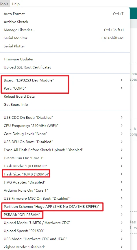
ESP32S3 Dev Module,16MB (128Mb)Flash,OPI PSRAM,Huge APP (3MB No OTA/1MB SPIFFS). - Dependencies: The
ESP_I2Slibrary bundled with the board package; no separate installation of a library with the same name is required. - Project:
Mic_Record_5s_Playback.ino. - Test environment: Perform the test in a relatively quiet environment, and keep an appropriate distance from the onboard microphone to avoid howling when the speaker plays back.
Code and Resource Download
Code download: - lesson-10/Mic_Record_5s_Playback
4. Software Operation Steps
Open the project in the Arduino IDE:
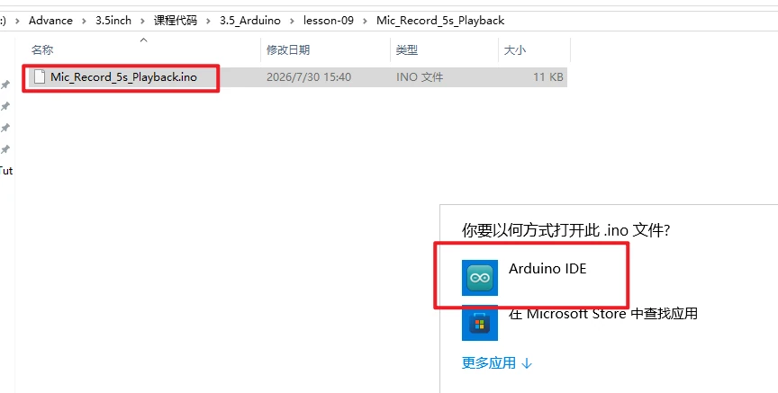
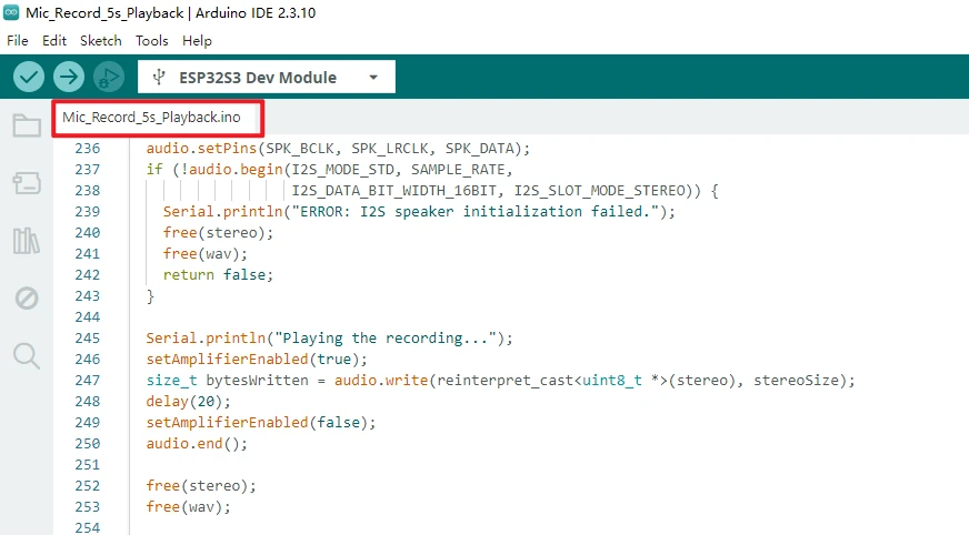
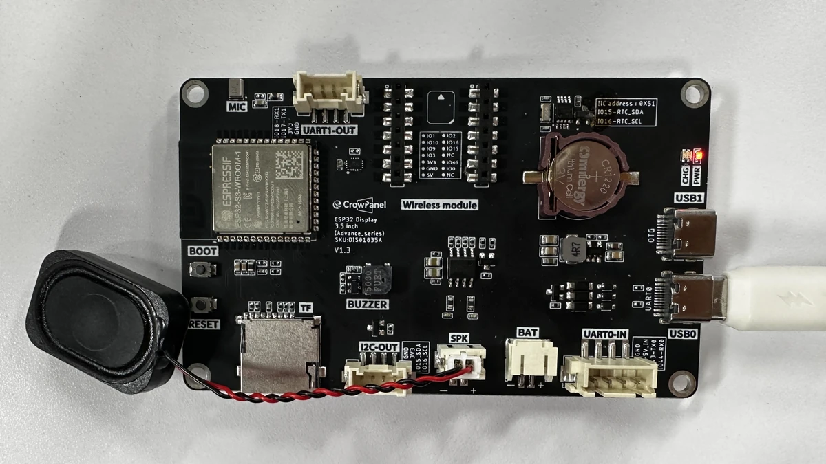
Connect an external speaker, and use a USB cable that supports data transfer to connect the CrowPanel Advance 3.5inch development board to the computer. Wait for the computer to recognize the serial port.
In the Tools menu, set Board to ESP32S3 Dev Module, select the Port for the current development board, and set Flash Size to 16MB (128Mb), PSRAM to OPI PSRAM, and Partition Scheme to Huge APP (3MB No OTA/1MB SPIFFS).
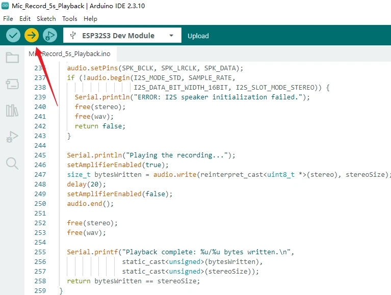
Click the Upload button to compile and flash the program, and wait for the output window to show that the upload is complete. If it stays stuck at Connecting... for a long time, check whether the serial port is occupied, and follow the board's requirements to use BOOT/RESET to enter download mode.
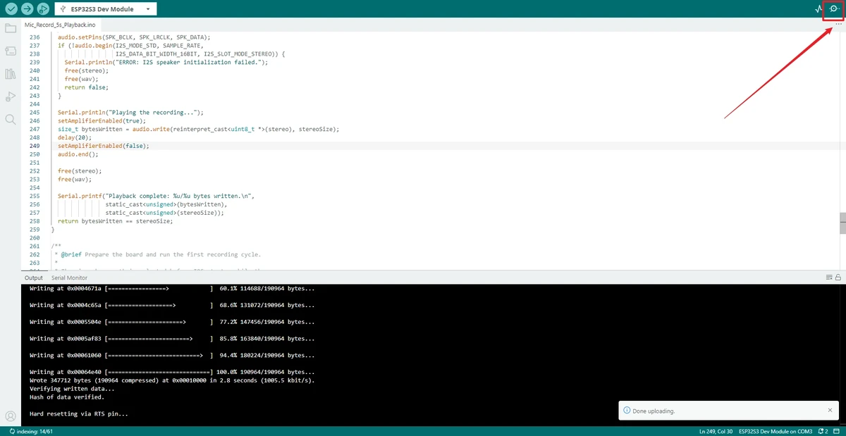
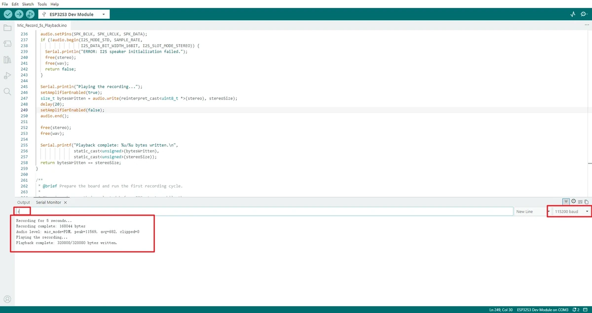
After the upload completes, open the Serial Monitor in the top-right corner and set the baud rate to 115200. After the board resets, it automatically records 5 seconds of audio and plays it back once. If you need to record again, enter r or R in the Serial Monitor and send it.
Note: This lesson depends on ESP_I2S.h, which is bundled with Arduino-ESP32 3.3.8. If you use an older ESP32 Core, ESP_I2S.h or the recordWAV() interface may not be found.
5. Hardware Operation Steps
Confirm that the development board is the CrowPanel Advance 3.5inch ESP32-S3 development board, and connect a speaker or the audio output module provided with the course. Use a USB data cable to connect the development board to the computer.
Keep the development board placed steady, and make sure the onboard microphone and speaker are not blocked. After the program outputs Recording for 5 seconds..., speak at a normal volume near the microphone. After you finish speaking, wait for the recording to complete. When the serial output shows Playing the recording..., the onboard speaker should play back the sound just recorded. During playback, do not place the microphone directly against the speaker, to avoid howling.
After the first playback ends, send r or R in the Serial Monitor input box, speak again, and confirm that the development board re-runs the 5-second recording and playback flow.
6. Key Code Explanation
This section explains only the current lesson code for the CrowPanel Advance 3.5inch. There are three key points in the code: the two-wire PDM microphone input on GPIO9 / GPIO10; the I2S amplifier output on GPIO13 / GPIO11 / GPIO12; and the DC bias removal, noise gating, and fade-in/fade-out processing applied to the recorded data before playback, which reduces speaker noise.
6.1 3.5inch Audio Pin Mapping
constexpr int MIC_CLK = 9;
constexpr int MIC_DATA = 10;
constexpr int MIC_SELECT = 45;

constexpr int SPK_BCLK = 13;
constexpr int SPK_LRCLK = 11;
constexpr int SPK_DATA = 12;
constexpr int AMP_CTRL = 21;
This defines all the control pins used by the 3.5inch onboard audio chain.
The 3.5inch onboard microphone uses a two-wire PDM input: GPIO9 is the PDM clock and GPIO10 is the PDM data. Speaker playback uses standard I2S output: GPIO13 is BCLK, GPIO11 is LRCLK, and GPIO12 is DATA.
GPIO45 is used to select the signal path between the onboard microphone and the wireless module; for this lesson it must be kept HIGH. GPIO21 is an active-low amplifier control pin that is pulled LOW only during playback, which reduces idle noise during the recording stage and speaker popping.
6.2 Recording Parameters for Reducing Noise
constexpr uint32_t SAMPLE_RATE = 16000;
constexpr uint32_t RECORD_SECONDS = 5;
constexpr float PLAYBACK_GAIN = 2.0f;
constexpr int16_t NOISE_GATE_LEVEL = 220;
constexpr size_t FADE_SAMPLE_COUNT = 320;
constexpr size_t WAV_HEADER_SIZE = 44;
SAMPLE_RATE is kept at 16 kHz, which is suitable for voice recording; RECORD_SECONDS means each recording lasts 5 seconds. The recorded data is 16-bit mono PCM, and 5 seconds takes about 160 KB. Before playback, a stereo buffer of about 320 KB is also created, so the Arduino IDE must enable OPI PSRAM.
PLAYBACK_GAIN is set to 2x to increase the playback volume while avoiding over-amplifying the idle noise. NOISE_GATE_LEVEL filters out very small background noise; FADE_SAMPLE_COUNT adds a short fade-in/fade-out at the beginning and end of the recording to reduce amplifier popping when it turns on and off.
6.3 Initializing the PDM Microphone Input
setAmplifierEnabled(false);
digitalWrite(MIC_SELECT, HIGH);

audio.setPinsPdmRx(MIC_CLK, MIC_DATA);
audio.begin(I2S_MODE_PDM_RX, SAMPLE_RATE,
            I2S_DATA_BIT_WIDTH_16BIT, I2S_SLOT_MODE_MONO);
The 3.5inch onboard microphone uses the two-wire PDM path on GPIO9 / GPIO10, so the code uses setPinsPdmRx() to set the microphone clock and data pins, then starts reception with I2S_MODE_PDM_RX.
Before recording starts, the amplifier is turned off to prevent the speaker path from introducing noise during the recording stage; GPIO45 is kept HIGH to select the MIC path. After normal initialization, the program enters the 5-second recording flow.
6.4 Obtaining WAV Data and Checking the Recording Result
uint8_t *wav = audio.recordWAV(RECORD_SECONDS, &wavSize);
audio.end();

if (wav == nullptr || wavSize <= WAV_HEADER_SIZE) {
  Serial.println("ERROR: Recording failed (check PSRAM and microphone pins).");
  free(wav);
  return false;
}
recordWAV() captures sound for the specified duration in one shot and prepends a standard 44-byte WAV file header to the PCM data. After recording completes, the I2S receive channel is closed first, so that the same I2SClass object can be reconfigured later for speaker output. If a null pointer is returned or the data length is incorrect, the program does not continue playback, avoiding access to invalid memory.
6.5 Adding Noise Reduction to Recorded Data
AudioStats stats = normalizeRecording(mono, sampleCount);
applyFade(mono, sampleCount);

for (size_t i = 0; i < sampleCount; ++i) {
  int16_t sample = amplify(mono[i]);
  stereo[i * 2] = 0;
  stereo[i * 2 + 1] = sample;
}
The PCM data returned by recordWAV() is already mono. The code first calls normalizeRecording() to remove the DC bias and to zero out low-amplitude noise below NOISE_GATE_LEVEL; then it calls applyFade() to add a short fade-in/fade-out at the start and end of the recording, avoiding popping at the beginning and end of playback.
The playback buffer is still a stereo I2S frame, but this board's speaker path is more stable using the right channel, so the left channel is written as 0 and the right channel is written with the processed audio data. This keeps the I2S stereo frame format while reducing noise from the unused channel.
6.6 Enabling the Amplifier and Writing Playback Data
audio.setPins(SPK_BCLK, SPK_LRCLK, SPK_DATA);
audio.begin(I2S_MODE_STD, SAMPLE_RATE,
            I2S_DATA_BIT_WIDTH_16BIT, I2S_SLOT_MODE_STEREO);

setAmplifierEnabled(true);
size_t bytesWritten = audio.write(reinterpret_cast<uint8_t *>(stereo), stereoSize);
delay(20);
setAmplifierEnabled(false);
audio.end();
After the microphone recording ends, the code first closes the PDM reception, then reconfigures the speaker output using the same I2SClass object. The I2S output starts in 16 kHz, 16-bit, stereo mode, and only then is GPIO21 pulled LOW to enable the amplifier.
audio.write() returns the number of bytes actually written; the "bytes written / total bytes" shown in the serial output should be equal. Finally, a 20 ms delay waits for the DMA to send the trailing data before the amplifier is turned off, which avoids continuously outputting idle noise after playback ends.
6.7 Serial Command to Repeat the Experiment
if (command == 'r' || command == 'R') {
  while (Serial.available()) Serial.read();
  recordAndPlay();
}
On power-up, the program automatically runs one recording and playback; afterwards, the main loop only waits for a serial command. Sending r or R calls the full flow again. Clearing the remaining characters prevents a newline or multiple characters pasted at once from triggering repeats.
7. Experimental Observations
After the program is flashed and the board resets, the Serial Monitor first displays the course name and the repeat prompt, then shows Recording for 5 seconds.... After about 5 seconds, the serial output shows the recorded byte count and prints audio statistics similar to Audio level: mic_mode=PDM, peak=xxxx, avg=xxx, clipped=0. Then Playing the recording... appears and the onboard speaker begins playing back the sound just recorded. After playback ends, the serial output shows the actual bytes written and the total bytes; the two being equal means the audio data was fully delivered to the I2S output.
After sending r or R in the Serial Monitor, the recording and playback flow above should run again. During continuous testing, the development board should not restart and the serial output should not show memory allocation errors, and the playback content should correspond to the sound spoken during each recording. The actual hardware audio effect and serial log must be verified as final before release.
8. Code Download
Code path: lesson-10/Mic_Record_5s_Playback