3.5inch_Lesson05_SD_BMP_Image
1. Course Introduction
This lesson initializes the LCD and TF card within an ESP-IDF project, reads 1.bmp through 5.bmp from the root directory of the TF card, and displays them in a loop on the screen. The project uses an Arduino-compatible entry point and LovyanGFX to render images, without using the LVGL UI. Pay special attention to the dimensions: in this lesson's code, displayImage(SD, IMAGE_1, 480, 320) means reading a landscape 24-bit BMP image of 480 x 320.
2. Learning Objectives
- Be able to prepare
480 x 320, 24-bit BMP images. - Be able to copy
1.bmpthrough5.bmpto the root directory of the TF card. - Be able to open and compile the
Lesson05_SD_Image_35/codeproject. - Be able to explain the LCD initialization, TF card mounting, file listing, and BMP row-refresh flow.
- Be able to distinguish, based on the serial log, between LCD initialization failure, TF card mounting failure, and image read failure.
3. Preparation
3.1 Hardware and Accessories
- CrowPanel Advance 3.5inch ESP32-S3 development board, 1 unit.
- USB Type-C data cable that supports data transfer, 1 unit, used for power, flashing programs, and viewing serial logs.
- Micro SD / TF card, 1 unit, used to store BMP images.
- USB card reader, 1 unit, used to copy images to the SD card from a computer.
- Computer, 1 unit, used to process images, copy files, and flash the ESP-IDF program.
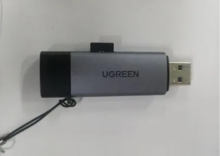
Note: It is recommended to format the SD card as FAT32 first. If the computer cannot reliably recognize the SD card, the development board will likely also fail to mount it properly.
3.2 Software and Files
- VS Code, the ESP-IDF extension, and
ESP-IDF 5.5.4already installed in Lesson01. - Windows Paint tool, or another image processing tool that can adjust pixel dimensions and export 24-bit BMP.
- This lesson's ESP-IDF project:
- This lesson's sample image materials:
Code and Resource Download
Code download:
Resource download:
4. SD Card and BMP Image Processing
4.1 Overall Processing Sequence
-
Select the image to be displayed, and use an image editing tool to crop or scale it to
480 × 320. -
Export the image as BMP format. It is recommended to keep it as 24-bit BMP, avoiding compressed formats or incompatible color formats.
-
Name the images
1.bmp,2.bmp,3.bmp,4.bmp,5.bmpaccording to the file naming requirements in the lesson code. -
Format the TF card with a common FAT file system, and copy
1.bmpthrough5.bmpto the root directory of the TF card.
Note: The 3.5inch lesson uses
480 × 320image resources. Do not directly use the 2.4inch320 × 240images, otherwise you may see incorrect display proportions, image misalignment, or incomplete display.
4.2 Image Preparation
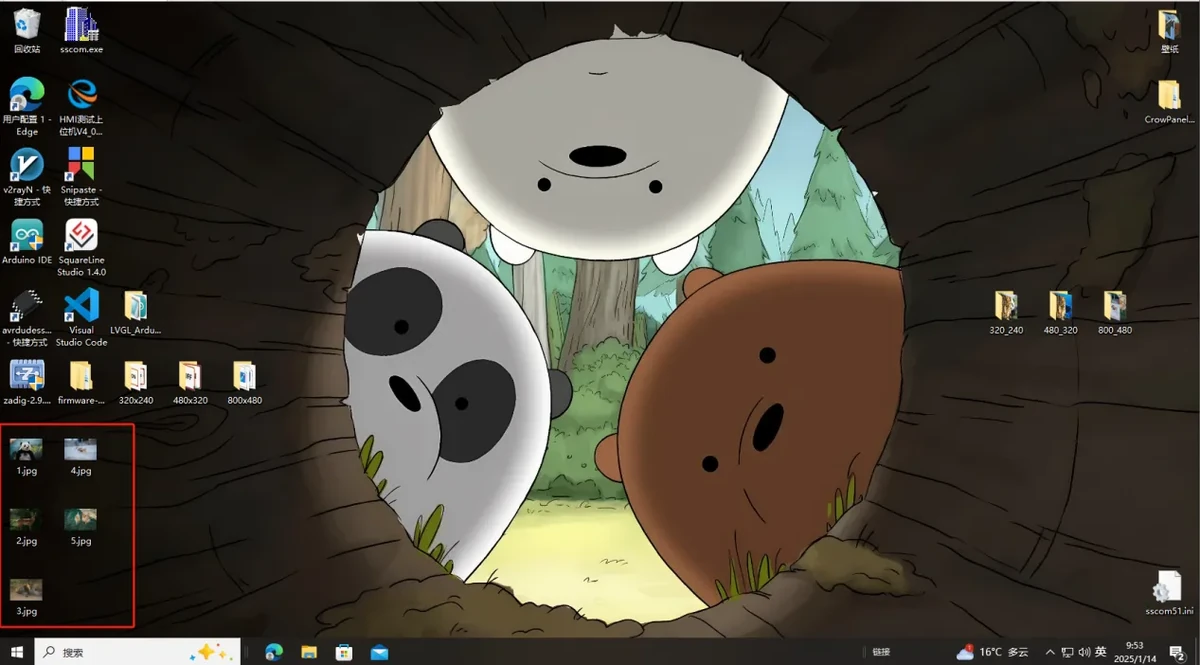
Select an image to display on the screen; you may use an image you downloaded yourself or directly use the sample materials provided with this course. The image can first be saved to the desktop or another easily accessible location.
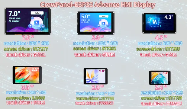
The official tutorial provides image resolutions corresponding to different screen sizes. The 3.5inch screen used in this course has a resolution of 480x320.
4.3 Open the Image Processing Tool
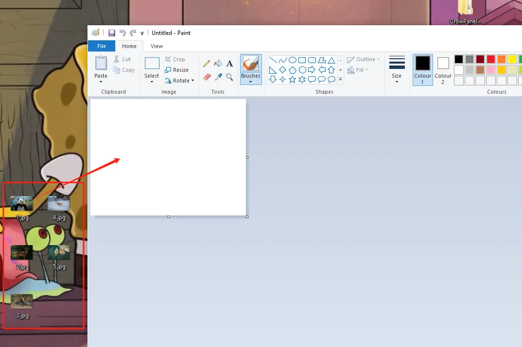
Open the "Paint" tool in Windows.
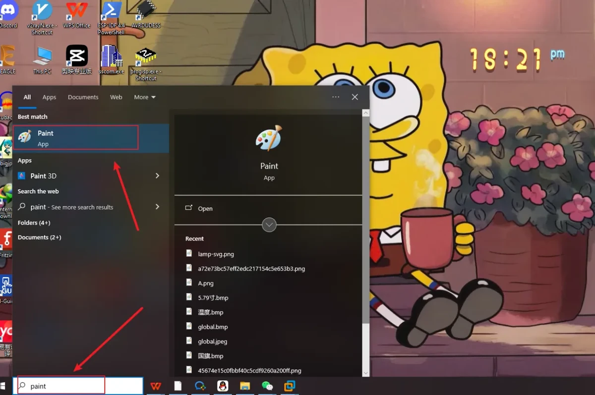
Drag the prepared image into the Paint tool, or use Paint's Open function to select the image file.
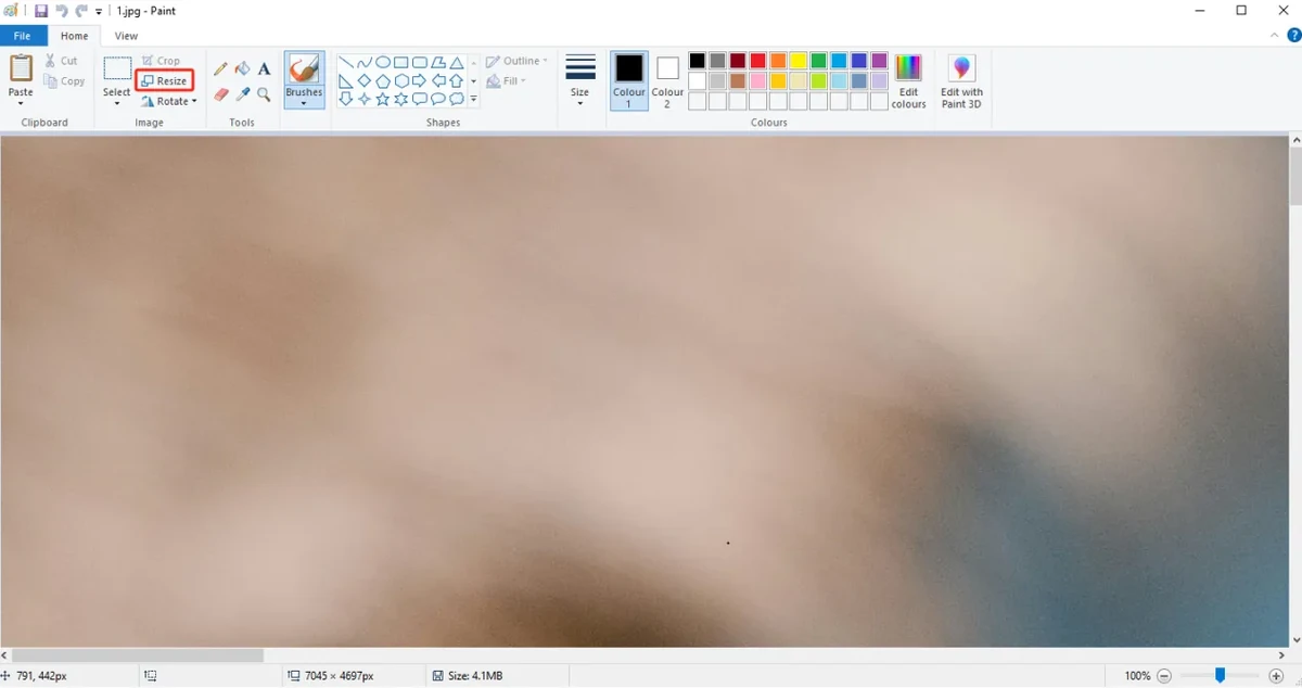
4.4 Adjust the Image Pixel Dimensions
Click the Resize function in the Paint tool, switch the unit to pixels, then set the horizontal and vertical dimensions to:
The figure below is for illustration purposes. Please adjust the appropriate resolution according to the different sizes you are actually using.
-
(Resolution for 4.3-inch, 5.0-inch, and 7.0-inch screens: 800x480)
-
(Resolution for 3.5-inch screen: 480x320)
-
(Resolution for 2.4-inch and 2.8-inch screens: 320x240)
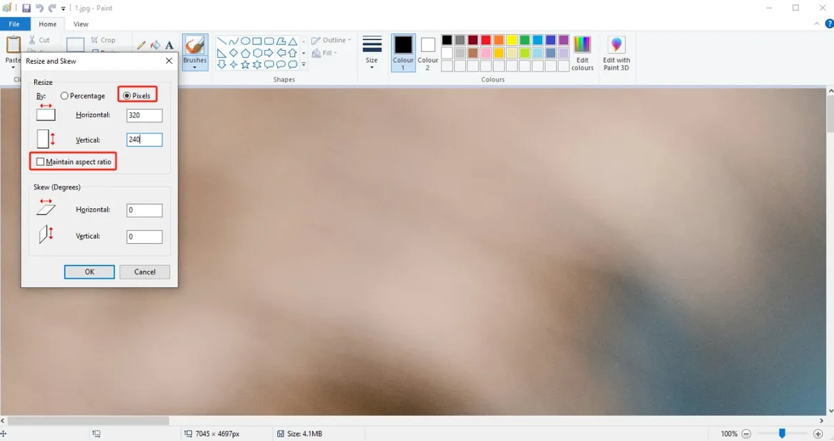
Click OK to complete the image size adjustment.
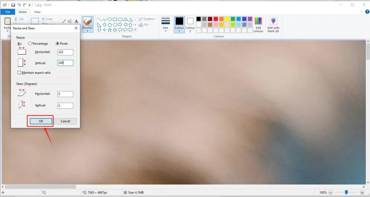
After adjustment, check whether the image proportions and content meet expectations.
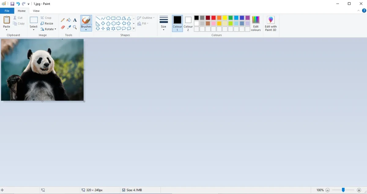
4.5 Save As 24-bit BMP
Select Save As, and save the processed image to an easily accessible location on the computer.
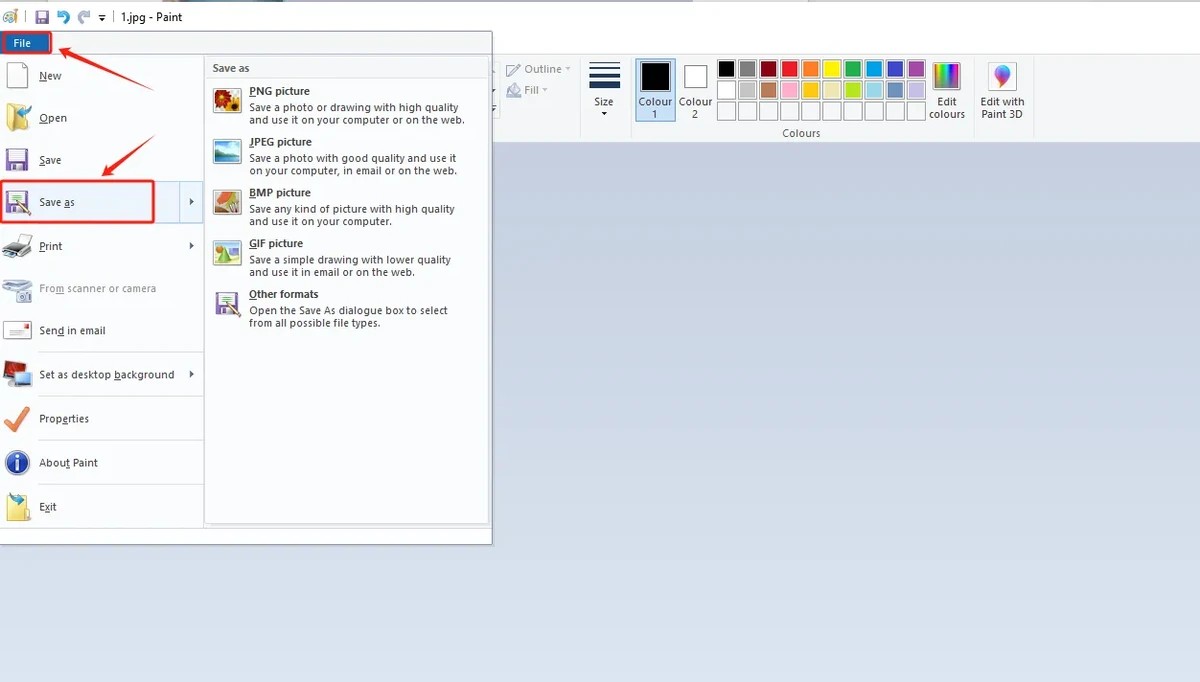
Select BMP as the save format, and ensure the image depth is 24-bit. It is recommended to name the files 1.bmp, 2.bmp, 3.bmp, 4.bmp, 5.bmp according to the default code path.
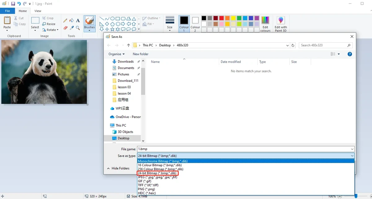
Note: Do not merely change the file extension. You must use an image tool to Save As BMP, and confirm that it is a 24-bit image depth.
4.6 Copy Images to the SD Card
Insert the Micro SD / TF card into the card reader, then connect the card reader to the computer.
Open the SD card drive, and copy the processed 1.bmp through 5.bmp to the root directory of the SD card.
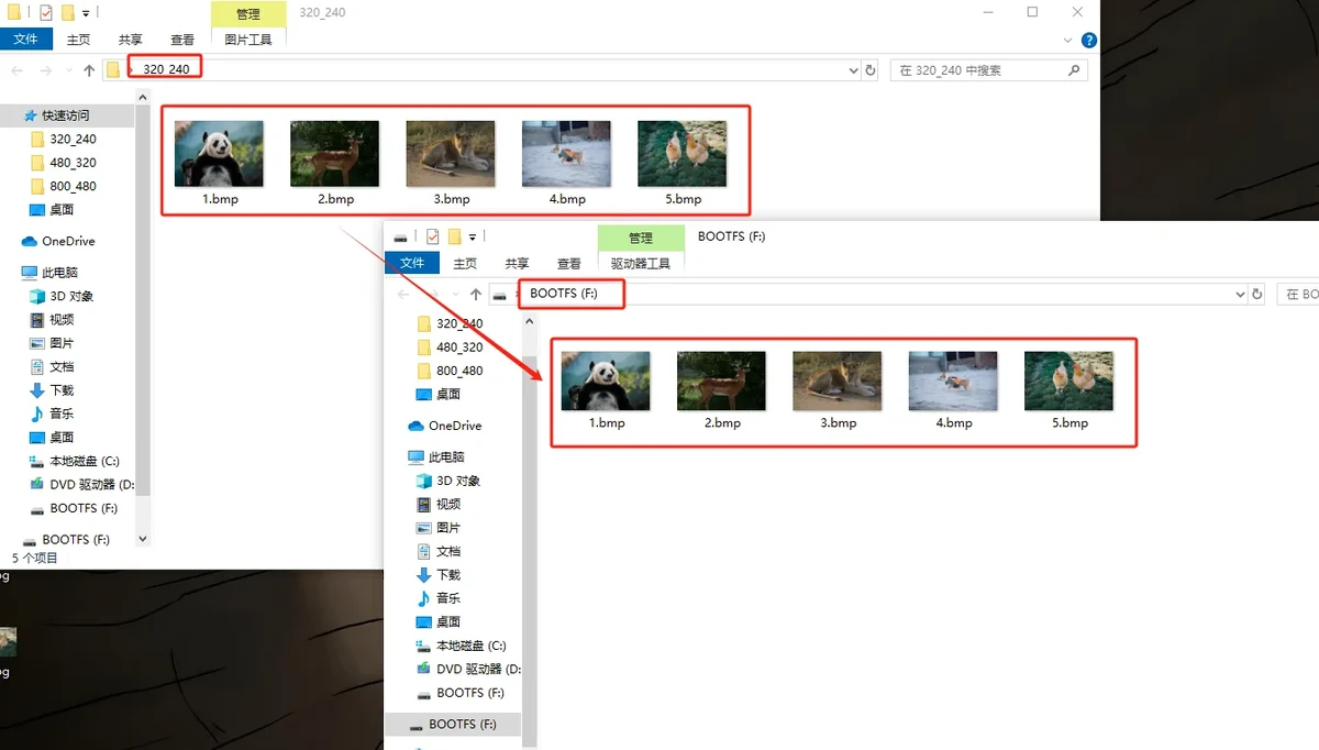
The recommended SD card root directory structure is as follows:
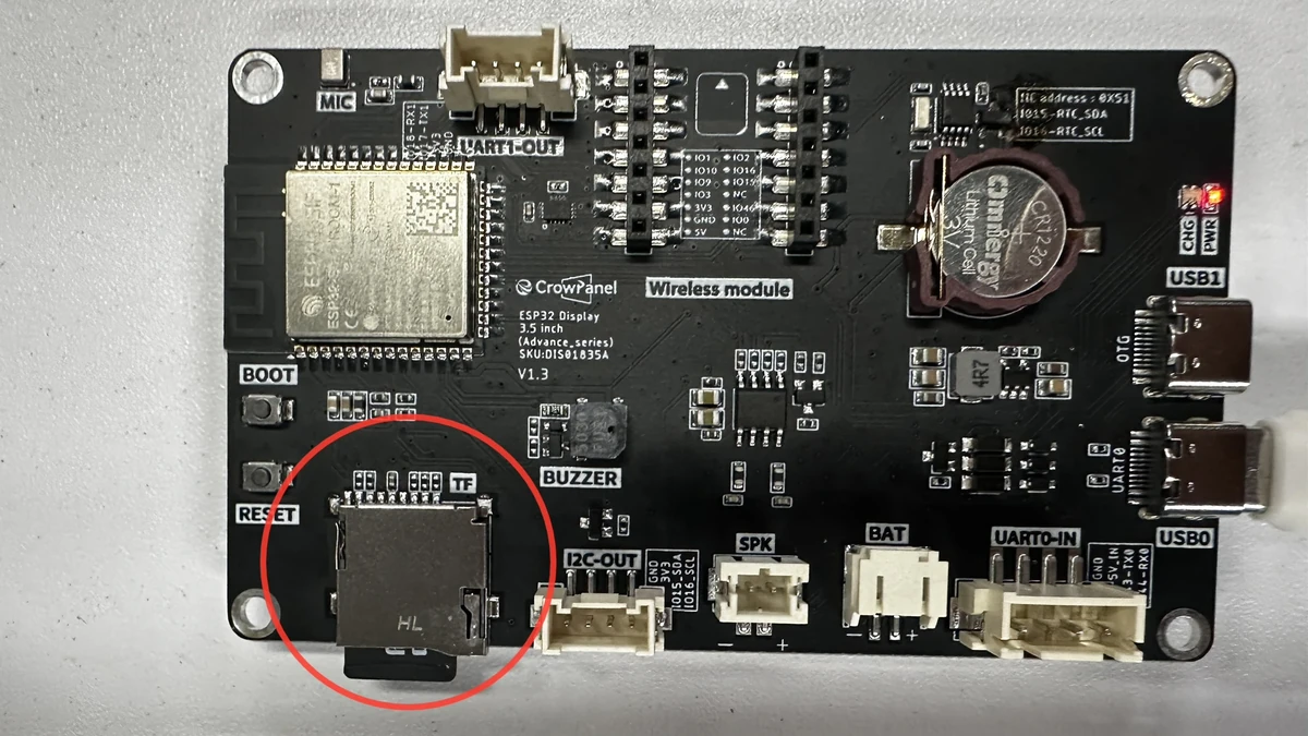
After copying, safely eject the SD card and remove it from the card reader, then insert it into the SD card slot of the CrowPanel Advance HMI 3.5inch.
Note: The default code for this lesson reads the SD card root directory paths /1.bmp through /5.bmp; do not place the images in subfolders. The file names must match the code exactly; it is recommended to use English and numeric naming, avoiding Chinese characters, spaces, and special symbols.
5. ESP-IDF Software Operation Steps
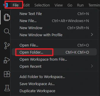
In VS Code, select File -> Open Folder... to open the root directory of this lesson's ESP-IDF project.
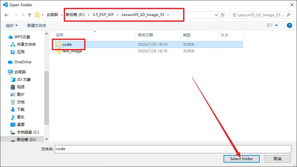
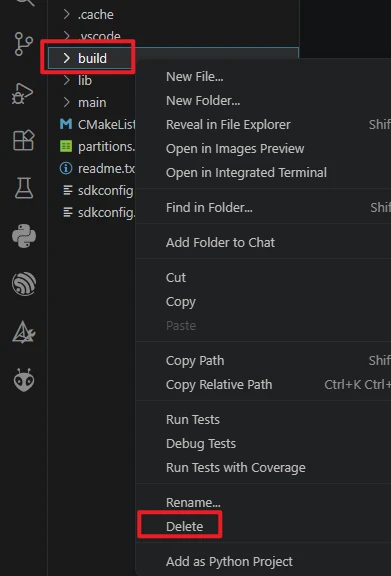
After opening the project, first execute Build -> Delete to clear the build cache and path records generated by the old project. After switching computers, switching the ESP-IDF version, or copying the project, it is recommended to do this step first.
Confirm that VS Code has loaded ESP-IDF 5.5.4. If the version shown in the status bar or indicated by the ESP-IDF extension is incorrect, return to the installation steps in Lesson01 and reselect the 5.5.4 environment.

Insert the SD card into the development board's TF card slot, and connect the development board to the computer using a USB cable that supports data transfer.
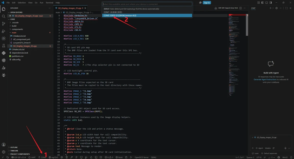
Click the serial port location in the bottom status bar of VS Code, and select the actual COM port recognized by the computer.
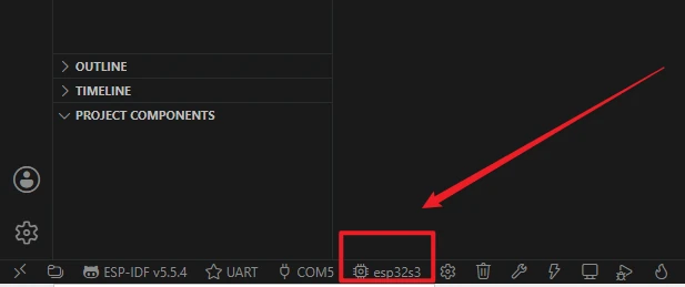
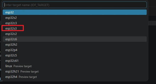
Click the target chip location in the status bar, or run the command ESP-IDF: Set Espressif Device Target, and select esp32s3 as the target chip. The reference images are for illustrating the entry point; the actual selection should follow this course's esp32s3.
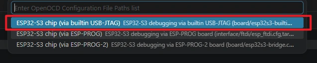
When selecting the debug configuration, choose the configuration that matches the ESP32-S3 development board, such as the ESP32-S3 built-in USB-JTAG or the corresponding ESP32-S3 OpenOCD configuration. Ordinary UART flashing mainly relies on the serial port and correct target chip settings.
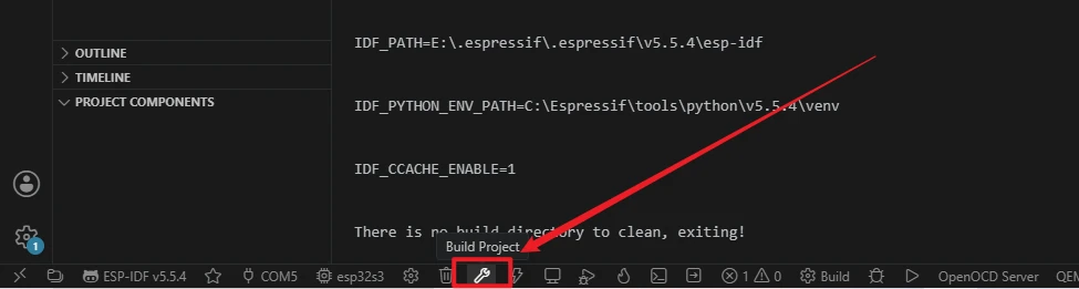
Click the Build button in the status bar to start compiling, or run the following in the ESP-IDF terminal:
The first compilation needs to download and generate dependencies, so it will take a relatively long time; continue to flashing only after you see the Build success message.
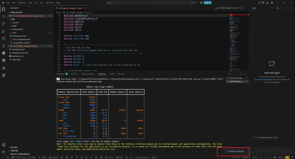
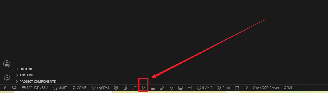
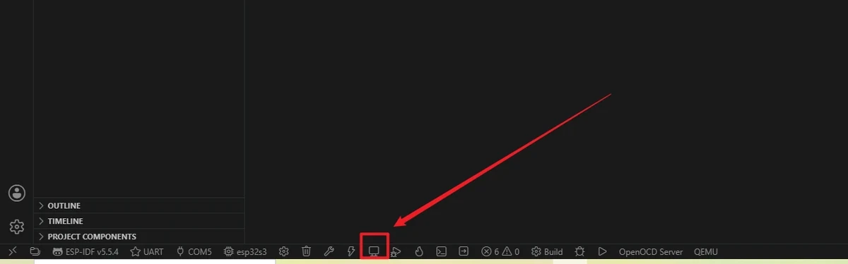
Confirm that the flashing method is UART, then click the lightning icon Flash, or run the following in the ESP-IDF terminal:
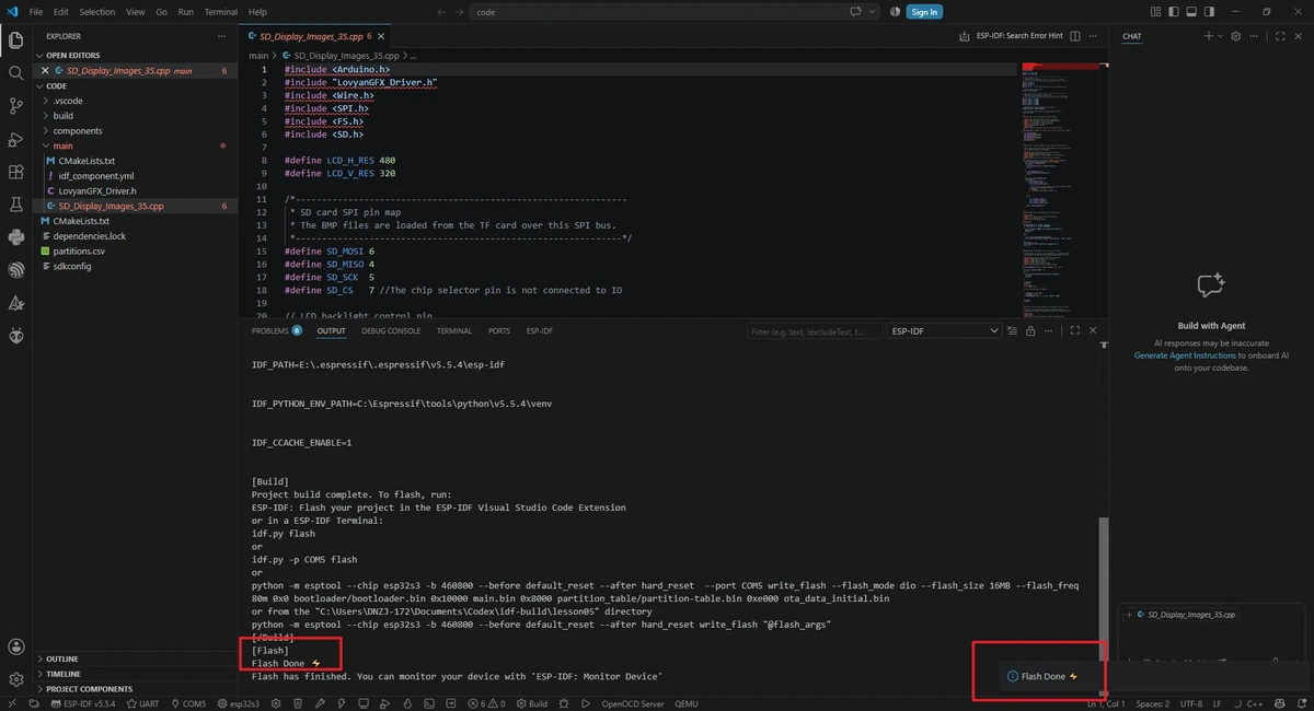
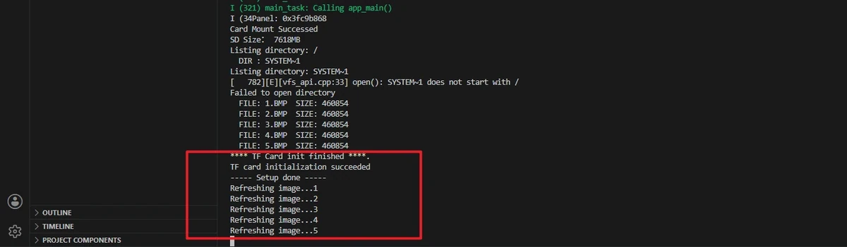
After flashing is complete, click Monitor. If the serial port shows Card Mount Successed, SD Size, Listing directory: /, and the file list 1.bmp through 5.bmp, it indicates that the SD card mounting and file preparation are basically normal. At this point the LCD will first display SD_Card OK, then enter the image slideshow.
6. Key Code Explanation
6.1 LCD and Backlight Initialization
pinMode(LCD_BL_PIN, OUTPUT);
digitalWrite(LCD_BL_PIN, HIGH);

lcd.configure();

if (lcd.getPanel() == nullptr)
{
  Serial.println("Panel pointer is null after configure!");
  while (true) { delay(1000); }
}

if (!lcd.begin())
{
  Serial.println("Display init failed!");
  while (true) { delay(1000); }
}
The program first turns on the backlight, then configures and starts the LCD. If getPanel() is null or lcd.begin() fails, the problem lies in the display driver or hardware connection, and you should not continue troubleshooting the TF card.
6.2 TF Card Mounting
SD_SPI.begin(SD_SCK, SD_MISO, SD_MOSI);
if (!SD.begin(SD_CS, SD_SPI, 80000000))
{
  Serial.println(F("ERROR: File system mount failed!"));
  SD_SPI.end();
  return 1;
}
The TF card is mounted via an independent SPI bus. Mount failures are usually related to the TF card format, card slot contact, SPI pins, CS pin, or card capacity compatibility. It is recommended to use a TF card of common capacity and format it as FAT32.
6.3 File Listing
After successful mounting, the program lists the root directory files. The serial port should show 1.bmp through 5.bmp. If the target files are not in the list, subsequent display will definitely fail.
6.4 BMP Row Refresh
f.seek(54);
int X = x;
int Y = y;
uint8_t RGB[3 * X];

for (int row = 0; row < Y; row++)
{
  f.seek(54 + 3 * X * row);
  f.read(RGB, 3 * X);
  lcd.pushImage(0, row, X, 1, (lgfx::rgb888_t *)RGB);
}
The code skips the 54-byte BMP header, then reads one row of RGB888 data at a time and pushes it to the LCD. This keeps memory usage low, but requires the image to be an uncompressed 24-bit BMP with dimensions matching the passed-in 480 x 320.
6.5 Image Slideshow
Each image is displayed for 5 seconds, then switches to the next one. If an image is missing or in an incorrect format, the serial port will show file open or display anomalies, and the screen may stay on the previous image.
7. Experimental Results
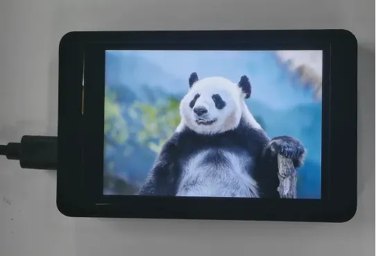
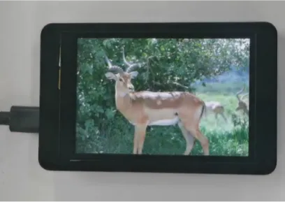
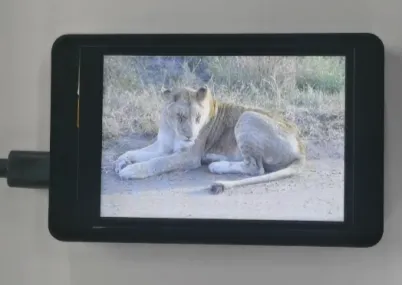
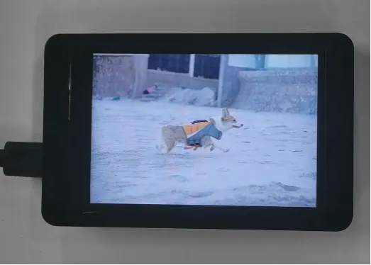
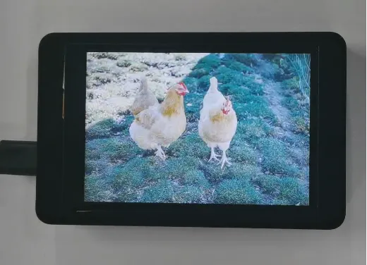
The serial port shows the panel pointer, TF card mounting status, card capacity, and file list. The screen first displays SD_Card OK, then switches to a new image every 5 seconds. The 5 images loop continuously and should not show restarts, black screens, or obviously distorted colors.
8. Code Download
**Code download link: **
Resource download: