4.3_5.0_7.0inch_Lesson04_SD_Image_Slideshow
1. Course Introduction
In this lesson, an SD card is connected over a dedicated SPI bus. The program reads 1.bmp through 5.bmp from the root directory. After the program starts running, the screen first displays the SD card initialization status, then switches to a new BMP image every 5 seconds. The serial port simultaneously outputs the SD card type, capacity, directory contents, and any error messages.
2. Learning Objectives
- Be able to explain the data flow among SD SPI, BMP files, and the LCD framebuffer.
- Be able to prepare five images according to the required naming and format, and copy them to the SD card root directory.
- Be able to distinguish mount failures, missing files, and abnormal image formats based on the serial port log.
3. What You Need
-
One CrowPanel Advance 4.3 / 5.0 / 7.0 inch ESP32-S3 HMI development board.
-
1.bmpthrough5.bmpfrom the800_480asset folder. -
Windows Paint, or any other image editing tool that can adjust pixel dimensions and export a 24-bit BMP.
-
Arduino
SD,FS,SPI,Wiredependencies and the LovyanGFX library. -
The LCD display code for this lesson references
LovyanGFX.hppand the RGB screen driver files underlgfx/v1/platforms/esp32s3throughLovyanGFX_Driver.h. Before compiling, confirm that a complete, workingLovyanGFXlibrary remains in the Arduinolibrariesdirectory. It is not recommended to keep two same-named library copies such asLovyanGFXandLovyanGFX-masterat the same time, as the Arduino IDE may then select an unexpected library version. -
Project:
SD_CrowPanel_ESP32_Advance_HMI_4_3_5_0_7_0.ino. -
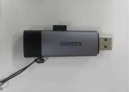
One microSD card and a card reader; file system and capacity compatibility are subject to verification on actual hardware. Note: It is recommended to format the SD card as FAT32 first. If your computer cannot reliably recognize the SD card, the development board will likely also fail to mount it properly.
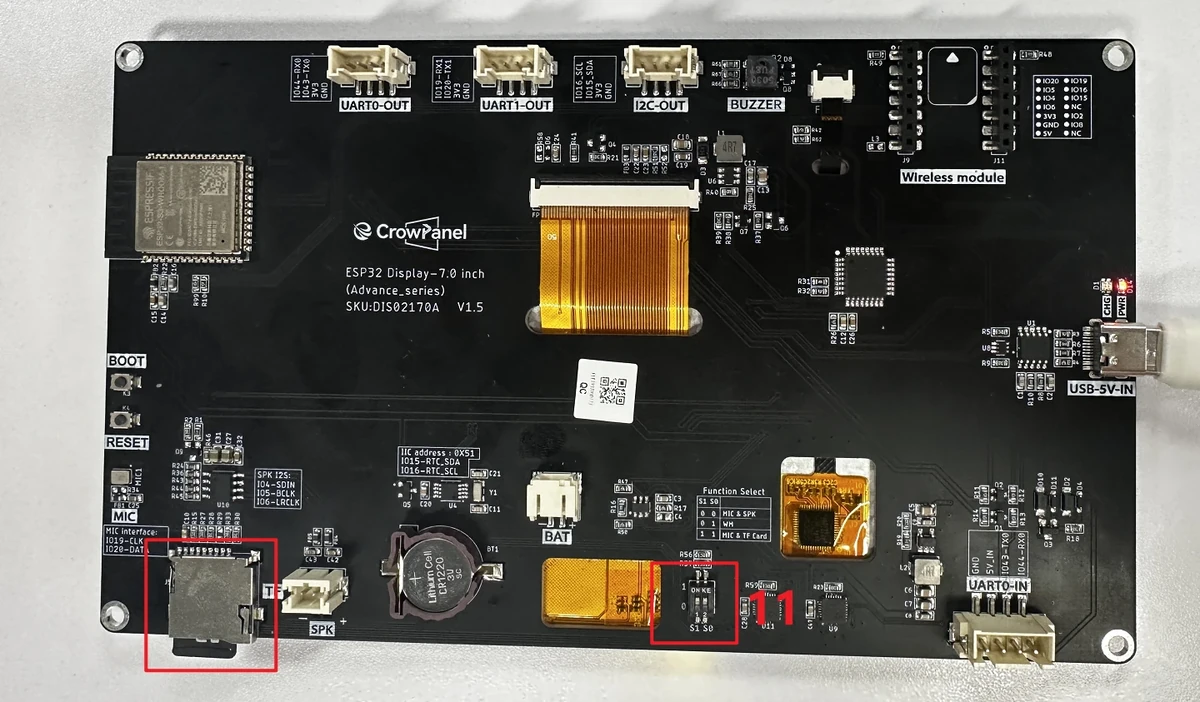
Note: When using the SD/TF card feature on the large-size 4.3 / 5.0 / 7.0 inch boards, you must set the function select switch to 11, which corresponds to MIC&TF Card on the official page. If the switch remains at 00 or 01, you may encounter SD initialization failure or unstable card reading.
Code and Resource Download
Code download: - lesson-04
Resource download: - 5 BMP image assets total link
4. SD Card Handling and BMP Image Processing
4.1 Overall Processing Sequence
- Select the images to display, and use an image editing tool to crop or scale them to
800 × 480. - Export the images as BMP format. A 24-bit BMP is recommended; avoid compressed formats or incompatible color formats.
- Name the images
1.bmp,2.bmp,3.bmp,4.bmp,5.bmpaccording to the file name requirements in the lesson code. - Format the TF card with a common FAT file system, and copy
1.bmpthrough5.bmpto the TF card root directory.
Note: The large-size 4.3 / 5.0 / 7.0 inch boards use
800 × 480image assets. Do not use the 2.4 inch320 × 240images directly, otherwise you may see incorrect display proportions, image misalignment, or incomplete display.
4.2 Image Preparation
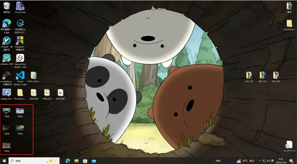
Select an image to display on the screen. You may use an image you downloaded yourself, or directly use the sample assets provided with this lesson. The image can first be saved to the desktop or another easy-to-find location.
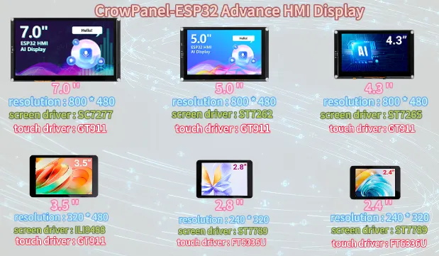
The official tutorial provides the image resolutions corresponding to different screen sizes. The CrowPanel Advance 4.3 / 5.0 / 7.0 inch ESP32-S3 HMI development board used in this lesson has a screen resolution of 800x480.
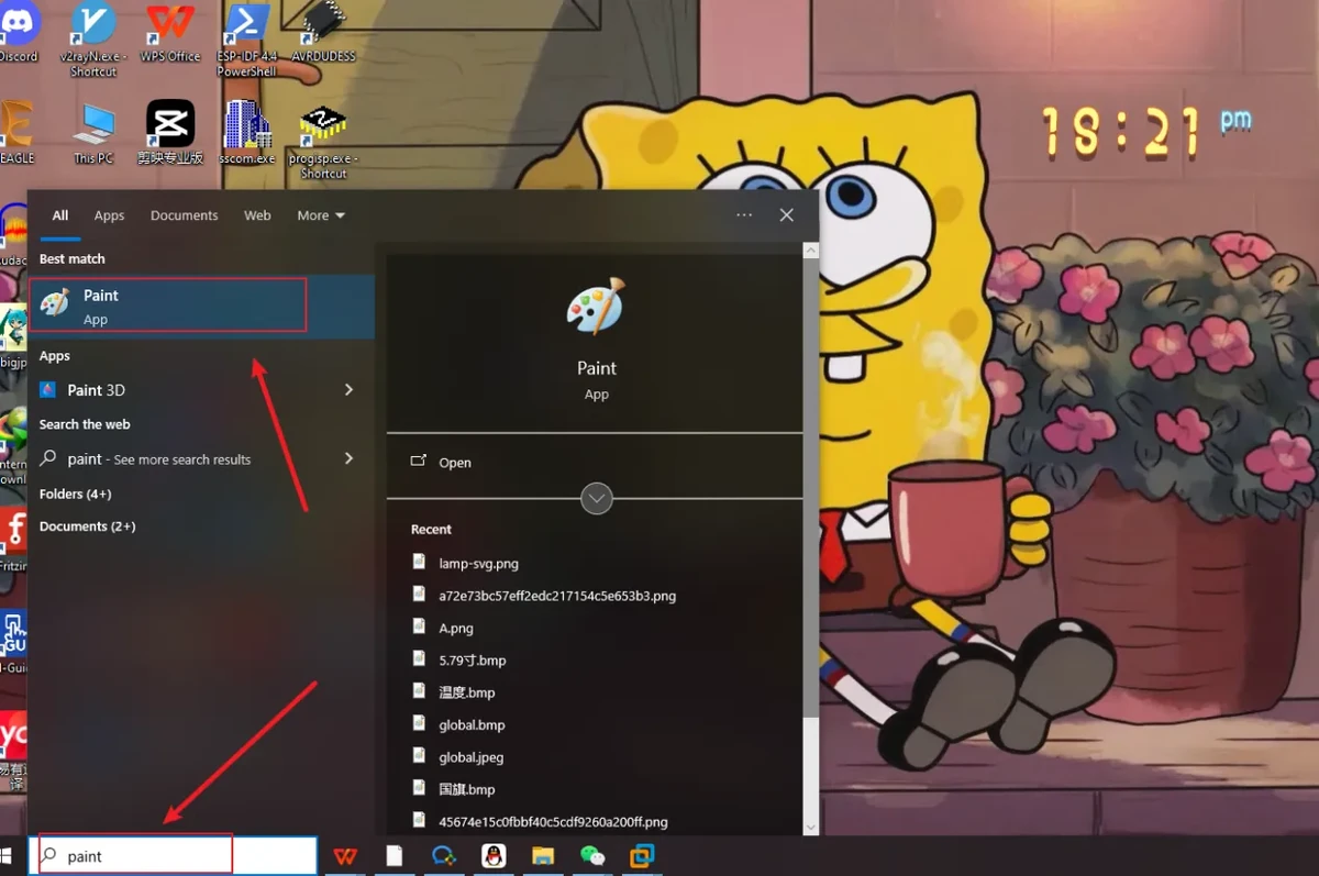
4.3 Open the Image Editing Tool
Open the Paint tool in Windows.
Drag the prepared image into Paint, or use Paint's Open function to select the image file.
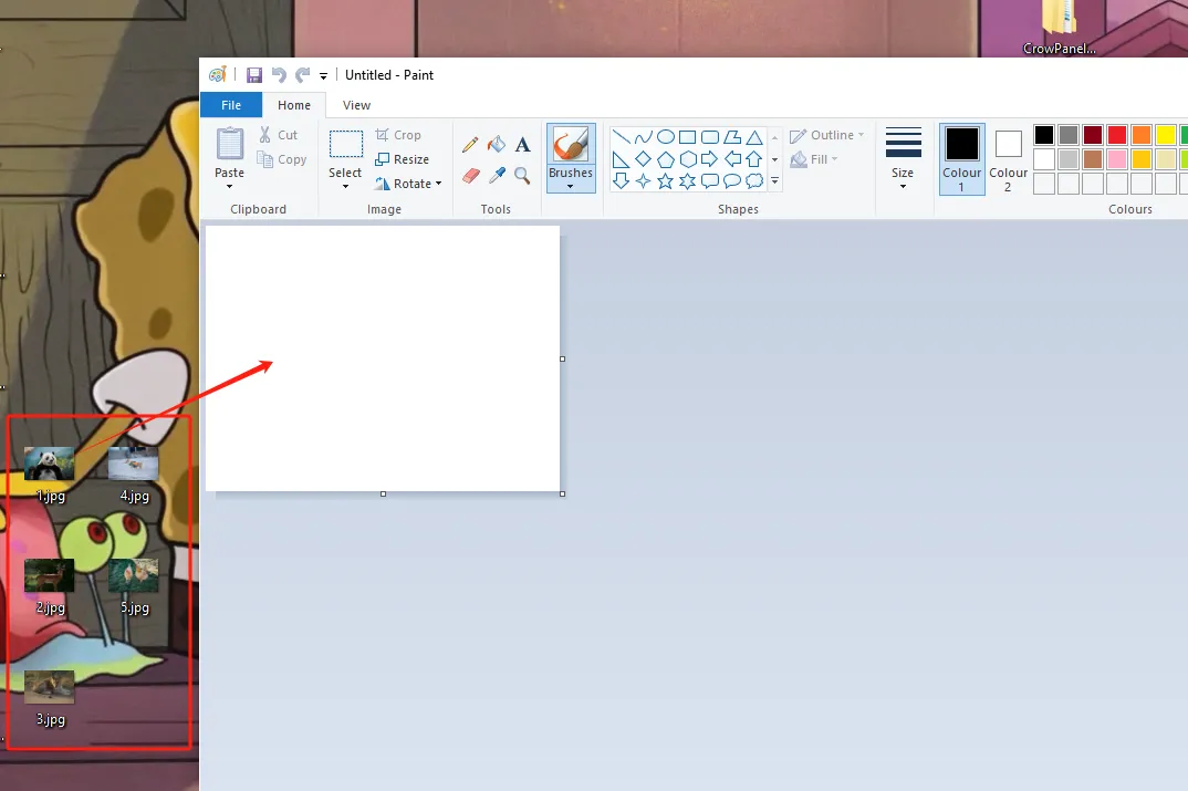
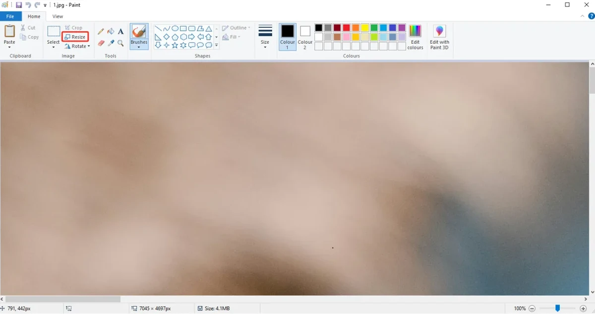
4.4 Adjust the Image Pixel Dimensions
Click the Resize function in Paint, switch the unit to pixels, and then set the horizontal and vertical dimensions to:
The figure below is for illustration purposes. Please adjust the appropriate resolution according to the different sizes you are actually using.
-
(Resolution for 4.3-inch, 5.0-inch, and 7.0-inch screens: 800x480)
-
(Resolution for 3.5-inch screen: 480x320)
-
(Resolution for 2.4-inch and 2.8-inch screens: 320x240)
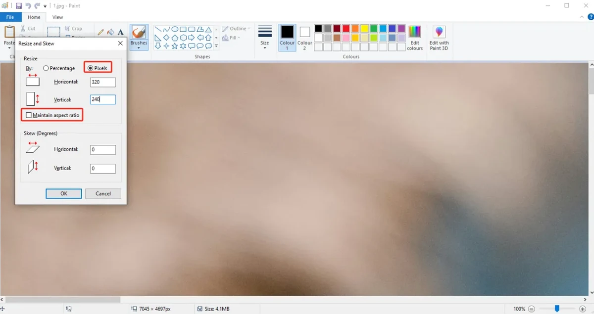
Click OK to complete the image dimension adjustment.
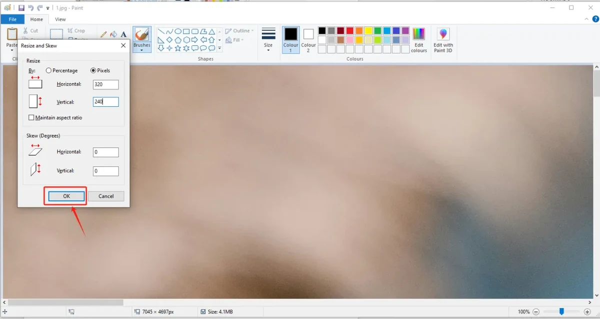
After the adjustment, check whether the image proportions and content meet your expectations.
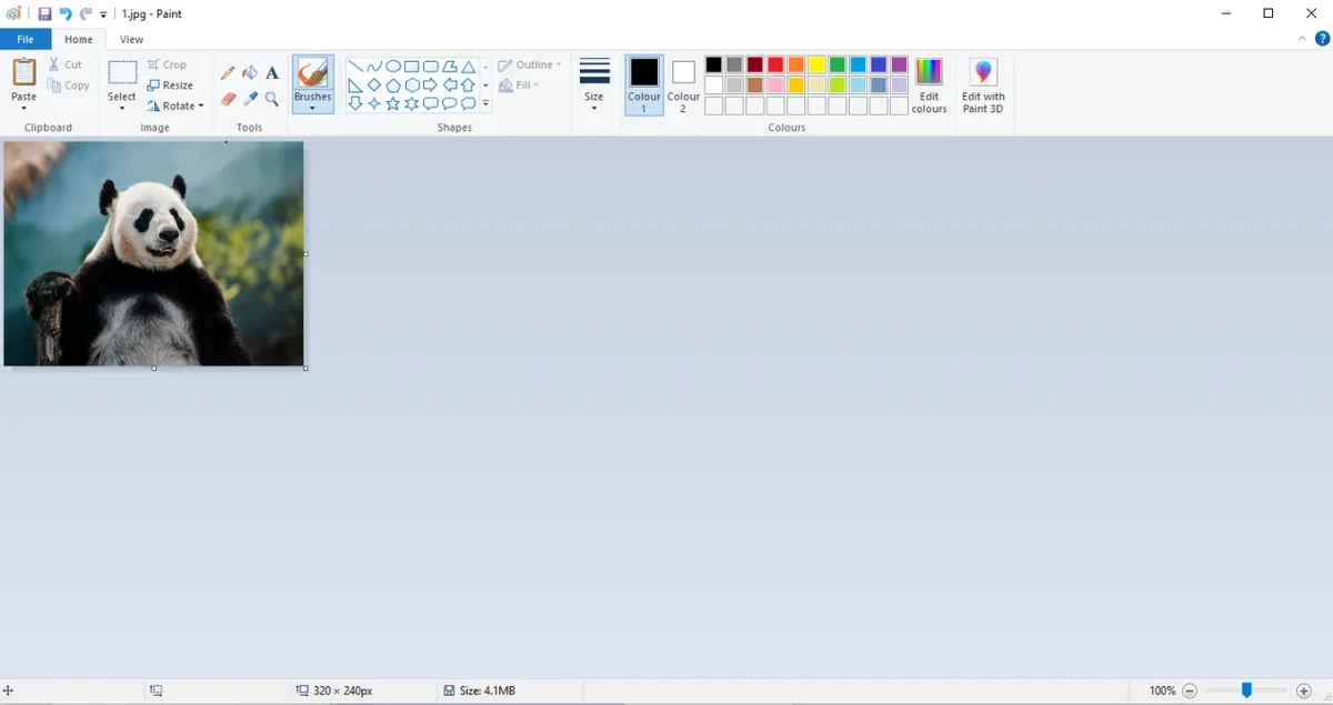
4.5 Save as 24-bit BMP
Choose Save As and save the processed image to a location on your computer that is easy to find.
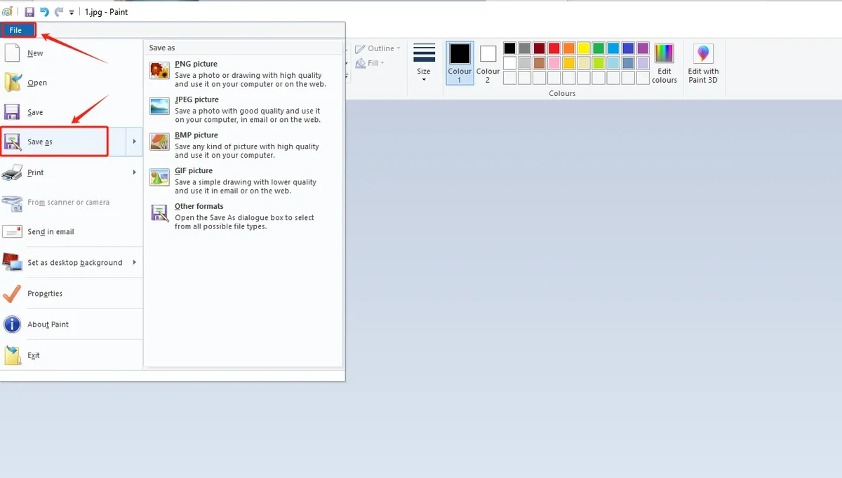
Select BMP as the save format and make sure the image depth is 24-bit. It is recommended to name the files 1.bmp, 2.bmp, 3.bmp, 4.bmp, 5.bmp following the default path in the code.
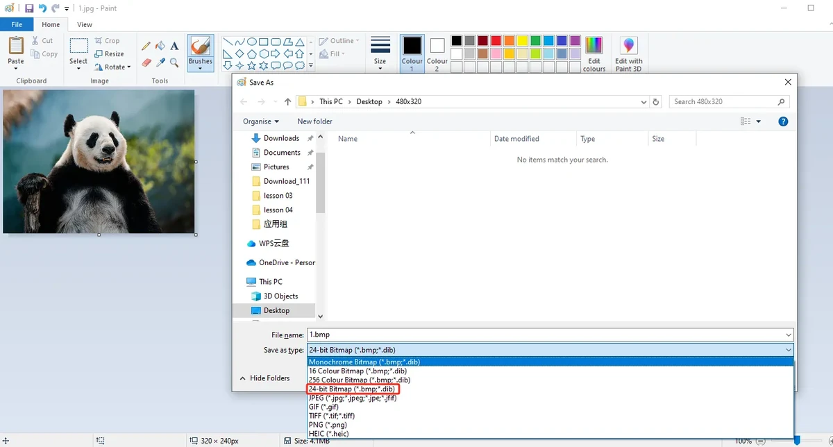
Note: Do not simply change the file extension. You must use an image tool to save it as BMP, and confirm that the image depth is 24-bit.
4.6 Copy Images to the SD Card
Insert the Micro SD / TF card into the card reader, then connect the card reader to your computer.
Open the SD card drive and copy the processed 1.bmp through 5.bmp to the SD card root directory.
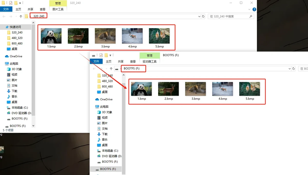
The recommended SD card root directory structure is as follows:
After copying is complete, safely eject the SD card and remove it from the card reader, then insert it into the SD card slot of the CrowPanel Advance 4.3 / 5.0 / 7.0 inch ESP32-S3 HMI development board.
Note: The default code for this lesson reads the SD card root directory paths /1.bmp through /5.bmp, so do not place the images in a subfolder. The file names must match the code exactly. It is recommended to use English alphanumeric names, avoiding Chinese characters, spaces, and special symbols.
5. Software Operation Steps
5.1 Open the Arduino Project and Add Library Files
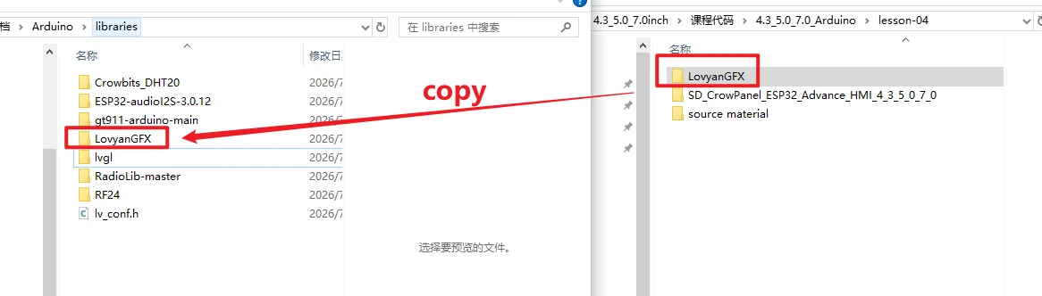
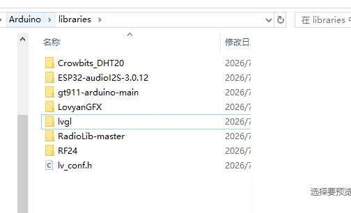
Copy the LovyanGFX folder from the lesson folder to C:\Documents\Arduino\libraries, and delete the old LovyanGFX-master to prevent library conflicts.
Open Arduino IDE Preferences to change the sketchbook path. After saving, restart the IDE so that the library files are recognized properly.
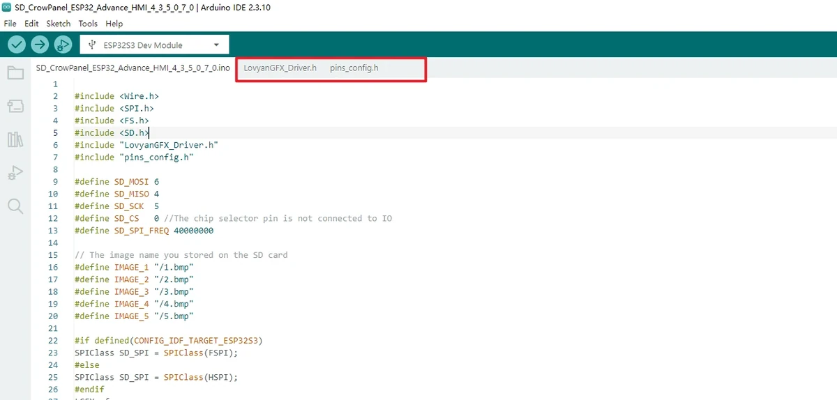
Open this lesson's project file using Arduino IDE:
After opening, first confirm that project files such as pins_config.h and LovyanGFX_Driver.h are in the same project directory, to avoid opening only a single .ino file and ending up with missing header files during compilation.
5.2 Configure the Development Board Parameters
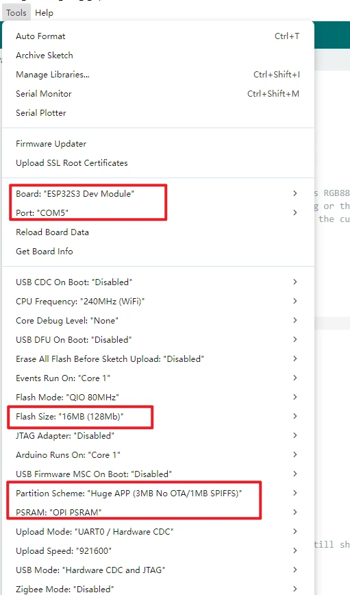
In the Arduino IDE Tools menu, confirm the following parameters:
Board: ESP32S3 Dev Module
Port: Select the serial port corresponding to the current board
Flash Size: 16MB (128Mb)
PSRAM: OPI PSRAM
Partition Scheme: Huge APP (3MB No OTA/1MB SPIFFS)
Serial Monitor baud: 115200
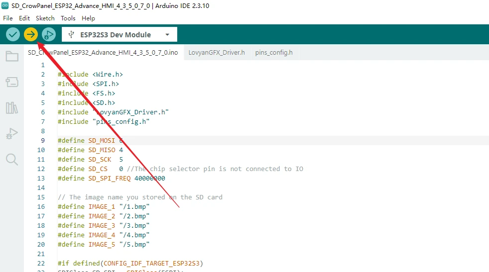
5.3 Compile and Upload the Program
Click the Upload button in the upper-left corner of the Arduino IDE and wait for compilation and flashing to complete.
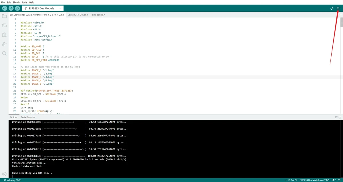
If the upload is stuck at Connecting..., refer to the download handling method in Lesson 01: check whether the port is occupied by the serial monitor, and if necessary use BOOT / RESET as required by the board to enter download mode.
5.4 Open the Serial Monitor to View Logs
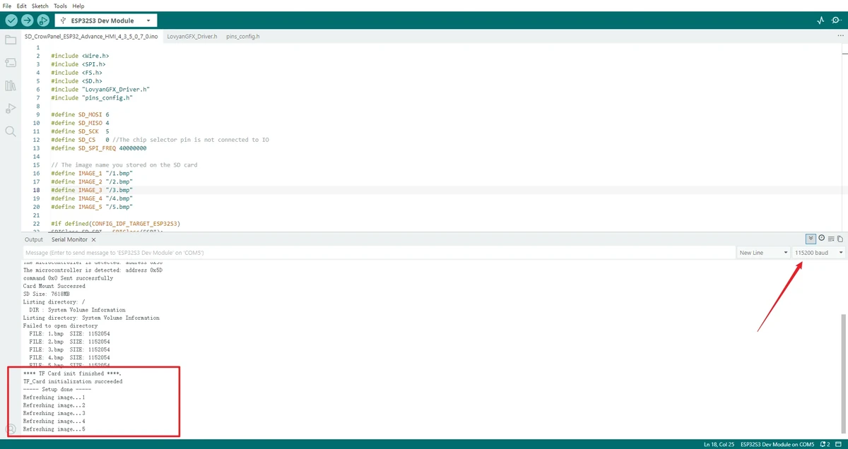
After flashing is complete, open the Serial Monitor and select a baud rate of 115200. When the program starts, it prints the SD card mount result, the SD card capacity, and the root directory file list.
If you can see Card Mount Successed, SD Size, Listing directory: /, and the file list of 1.bmp through 5.bmp in the serial output, it means the SD card mount and file preparation are basically normal. At this point the LCD will first display SD_Card OK, then enter the image slideshow.
6. Hardware Operation Steps
With power off, insert the microSD card in the correct orientation according to the card slot, and set the function select switch to 11. After confirming it is fully seated, connect the USB. 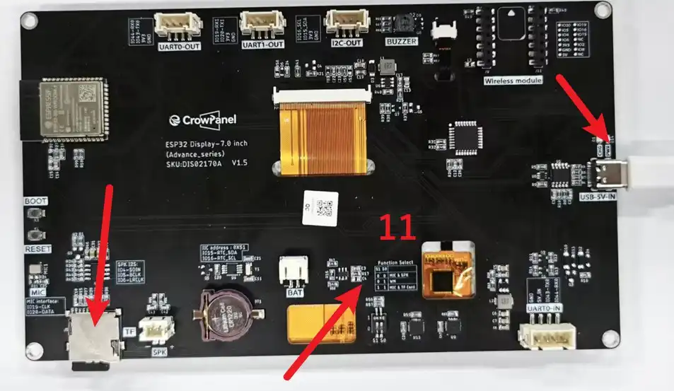
Observe whether the screen first displays SD_Card OK.
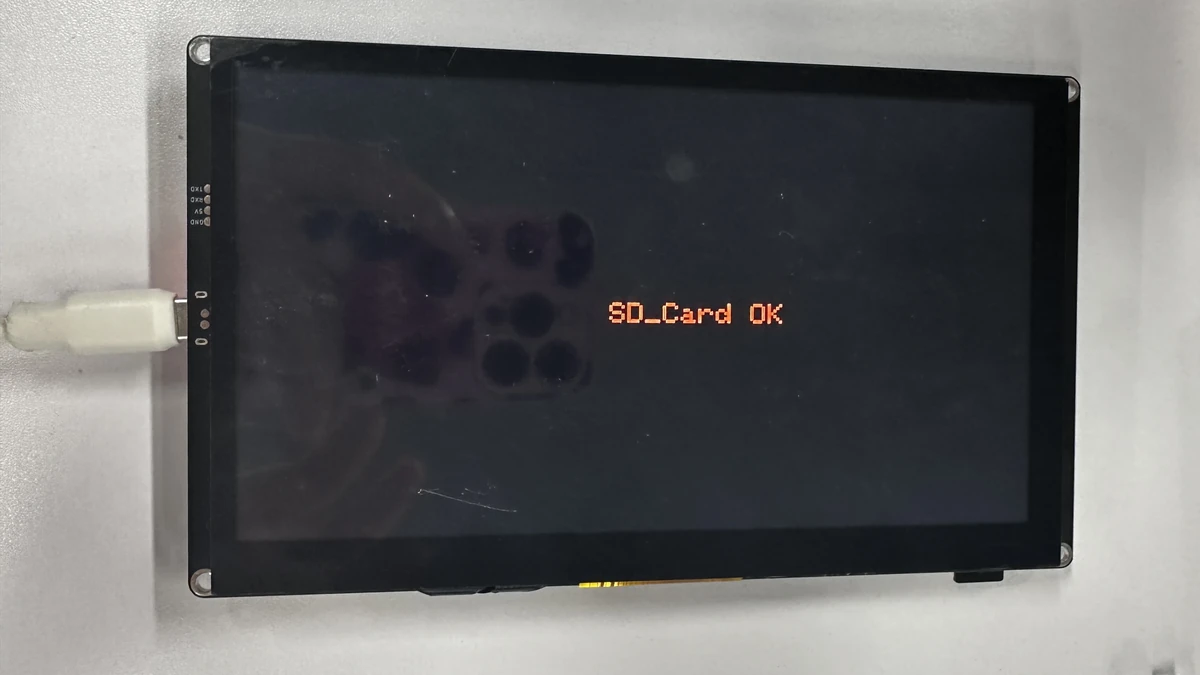
Wait for the image slideshow and confirm that the screen switches to a new BMP image approximately every 5 seconds.
7. Key Code Explanation
The SPI frequency affects card reading stability, and the file path must match the name on the card exactly. When troubleshooting unstable card reading, you may lower the frequency on the premise that the hardware allows it; the restored value is 40000000.
The program reuses the display driver's back buffer to organize the entire frame image at 16-bit color. A mismatch in resolution or color depth may cause misalignment or color abnormalities.
Each call reads a BMP from the file system and draws it at the specified coordinates. If the file cannot be opened, first check the path, the card mount, and the image format.
8. Experimental Observations
After the program is flashed and reset, the LCD first displays the SD card initialization status:
-
Displaying
SD_Card OK: The SD card was mounted successfully. -
Displaying
SD_Card Failed: The SD card failed to mount; check the SD card, its format, and the insertion status.
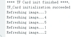
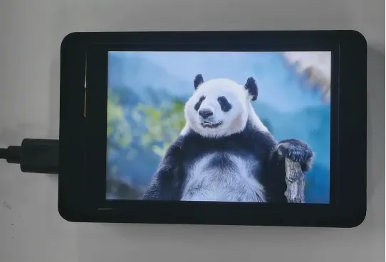
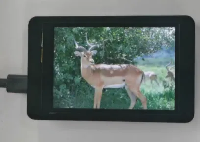
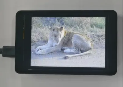
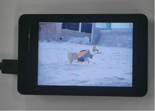
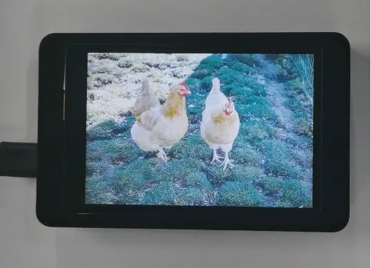
After the SD card is mounted successfully, the LCD cyclically displays the 5 BMP images on the SD card, with each image staying on screen for about 5 seconds.
9. Code Download
Code path: lesson-04