4.3_5.0_7.0inch_Lesson10_Microphone_Record_Playback
1. Course Introduction
In this lesson, we perform an audio input/output experiment on the CrowPanel Advance 4.3-inch / 5.0-inch / 7.0-inch large-size development boards: we use the onboard PDM microphone to record 5 seconds of audio, then play it back through the onboard I2S amplifier and speaker. After the program is flashed, it automatically records and plays back once. After playback finishes, sending r or R in the Serial Monitor triggers another recording and playback.
The audio control method on large-size boards differs from that on small-size boards: this lesson sends audio control commands via the I2C address 0x30 to select the microphone path and to mute or restore the amplifier's audio state.
2. Learning Objectives
- Be able to open and flash the Lesson 10 microphone record-and-playback project in the Arduino IDE.
- Be able to describe the data flow between PDM microphone recording, the WAV buffer, mono-to-stereo conversion, and I2S speaker playback.
- Be able to understand the roles of
recordWAV(),setPinsPdmRx(), andsetPins()inESP_I2S.h. - Be able to determine from the serial log whether recording, memory allocation, and I2S playback are working correctly.
- Be able to adjust
PLAYBACK_GAINbased on audio volume or distortion.
3. What You Need
- One CrowPanel Advance 4.3-inch / 5.0-inch / 7.0-inch large-size development board.
- Onboard PDM microphone and onboard I2S speaker amplifier.
- A USB data cable that supports data transfer.
- Arduino IDE.
- Development environment:
esp32 by Espressif Systems 3.3.8. - Install
esp32 by Espressif Systems3.3.8 via Boards Manager. - PSRAM must be enabled; this program requires approximately 160 KB of recording buffer and 320 KB of stereo playback buffer.
- This lesson's project:
Mic_Record_5s_Playback.ino. - Test environment: conduct the test in a relatively quiet environment, and keep an appropriate distance from the onboard microphone to avoid feedback (howling) during speaker playback.
Note: This lesson uses the onboard microphone and speaker. On large-size boards, set the Function Keys / function DIP switch to 00, which corresponds to MIC&SPK. If your current hardware revision multiplexes the microphone with the TF card on the 11 position, follow the silkscreen on the board and the official revision notes. Do not switch the DIP switch while powered on.
Code and Resource Download
Code download: - lesson-10/Mic_Record_5s_Playback
4. Software Operation Steps
Open the project in the Arduino IDE:

Connect an external speaker, and use a USB cable that supports data transfer to connect the CrowPanel Advance 4.3-inch / 5.0-inch / 7.0-inch development board to your computer. Wait for the computer to recognize the serial port. For large-size boards, set the Function Keys / function DIP switch to 00.

In the Tools menu, set Board to ESP32S3 Dev Module, select the current board's Port, and set Flash Size to 16MB (128Mb), PSRAM to OPI PSRAM, and Partition Scheme to Huge APP (3MB No OTA/1MB SPIFFS).

Click Upload to compile and wait for the upload to finish. If it gets stuck at Connecting..., check for port conflicts and use BOOT/RESET download mode as required by the board.

Open the Serial Monitor in the top-right corner, set the baud rate to 115200, and observe the log. After the board resets, it automatically records for 5 seconds and plays back once. To record again, type r or R in the Serial Monitor and send it.

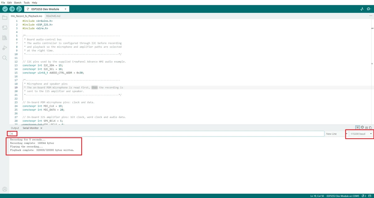
Note: This lesson depends on ESP_I2S.h, which is bundled with Arduino-ESP32 3.3.8. If you use an older ESP32 Core, you may not find ESP_I2S.h or the recordWAV() interface.
5. Hardware Operation Steps
Power off and confirm the function DIP switch is set to 00, corresponding to MIC&SPK. Confirm the board is the CrowPanel Advance 4.3-inch / 5.0-inch / 7.0-inch ESP32-S3 development board, and connect a speaker or the audio output module provided with the course. Use a USB data cable to connect the board to your computer.
After flashing, keep the surroundings quiet and wait for the serial output Recording for 5 seconds.... Speak normally toward the microphone or play a test sound; do not place your mouth close to the microphone and shout into it. Wait for the recording to finish, then it plays back automatically.
After the first playback ends, send r or R in the Serial Monitor input box, speak again, and confirm that the board re-runs the 5-second recording and playback sequence.
6. Key Code Explanation
6.1 Audio Control and Pins on Large-Size Boards
constexpr int I2C_SDA = 15;
constexpr int I2C_SCL = 16;
constexpr uint8_t AUDIO_CTRL_ADDR = 0x30;

constexpr int MIC_CLK = 19;
constexpr int MIC_DATA = 20;

constexpr int SPK_BCLK = 5;
constexpr int SPK_LRCLK = 6;
constexpr int SPK_DATA = 4;
I2C_SDA and I2C_SCL are used to access the onboard audio/backlight control chip at address 0x30. MIC_CLK and MIC_DATA are the PDM microphone inputs; SPK_BCLK, SPK_LRCLK, and SPK_DATA are the I2S amplifier outputs.
6.2 Audio Control Commands
bool sendAudioCommand(uint8_t command) {
  Wire.beginTransmission(AUDIO_CTRL_ADDR);
  Wire.write(command);
  return Wire.endTransmission() == 0;
}
This lesson uses sendAudioCommand() to write control commands to 0x30. Before recording, send 2 to select the microphone path, and send 249 to keep the speaker muted. Before playback, send 248 to unmute the amplifier. After playback ends, send 249 to mute, then send 3 to restore the default example audio state.
6.3 Recording Parameters
constexpr uint32_t SAMPLE_RATE = 16000;
constexpr uint32_t RECORD_SECONDS = 5;
constexpr float PLAYBACK_GAIN = 8.0f;
constexpr size_t WAV_HEADER_SIZE = 44;
SAMPLE_RATE is 16 kHz, suitable for voice recording; RECORD_SECONDS means each recording lasts 5 seconds; PLAYBACK_GAIN is the playback gain used to amplify the sound captured by the microphone; WAV_HEADER_SIZE is the length of a standard WAV file header, which must be skipped (44 bytes) when extracting the PCM data that follows.
6.4 PDM Microphone Recording
audio.setPinsPdmRx(MIC_CLK, MIC_DATA);
if (!audio.begin(I2S_MODE_PDM_RX, SAMPLE_RATE,
                 I2S_DATA_BIT_WIDTH_16BIT, I2S_SLOT_MODE_MONO)) {
  Serial.println("ERROR: PDM microphone initialization failed.");
  return false;
}

uint8_t *wav = audio.recordWAV(RECORD_SECONDS, &wavSize);
audio.end();
setPinsPdmRx() sets the clock and data pins for the PDM microphone. audio.begin() starts the I2S peripheral in PDM RX mode, with a sample rate of 16 kHz, a bit width of 16 bits, and a mono channel. recordWAV() records for the specified number of seconds and returns in-memory data with a WAV file header. After recording completes, call audio.end() to release the current I2S channel so it can later switch to standard I2S playback mode.
6.5 Recording Data Check
if (wav == nullptr || wavSize <= WAV_HEADER_SIZE) {
  Serial.println("ERROR: Recording failed (check PSRAM/memory). ");
  free(wav);
  return false;
}
recordWAV() needs to allocate memory for the recording data. If PSRAM is not enabled or memory is insufficient, wav may be null. If the data length is less than or equal to 44 bytes, it means only the file header was obtained and there is no valid PCM audio data. Under normal recording of 5 seconds at 16 kHz, 16-bit mono, the data volume is approximately 160 KB plus the WAV file header.
6.6 Mono-to-Right-Channel Stereo Conversion
uint8_t *monoBytes = wav + WAV_HEADER_SIZE;
size_t monoSize = wavSize - WAV_HEADER_SIZE;
size_t sampleCount = monoSize / sizeof(int16_t);
size_t stereoSize = sampleCount * 2 * sizeof(int16_t);

int16_t *stereo = static_cast<int16_t *>(
    heap_caps_malloc(stereoSize, MALLOC_CAP_SPIRAM | MALLOC_CAP_8BIT));
recordWAV() returns mono data with a WAV header, so the code first skips the 44-byte file header and then computes the number of samples. The onboard playback path uses standard I2S stereo data, so the code allocates a new stereo buffer and expands the mono data into stereo.
for (size_t i = 0; i < sampleCount; ++i) {
  stereo[i * 2] = 0;
  stereo[i * 2 + 1] = amplify(mono[i]);
}
The current audio output is mainly connected to the right channel, so the left channel is filled with 0 and the right channel is filled with the amplified recording data. amplify() clamps the maximum and minimum values to avoid numeric overflow.
6.7 Playback to the I2S Amplifier
audio.setPins(SPK_BCLK, SPK_LRCLK, SPK_DATA);
if (!audio.begin(I2S_MODE_STD, SAMPLE_RATE,
                 I2S_DATA_BIT_WIDTH_16BIT, I2S_SLOT_MODE_STEREO)) {
  Serial.println("ERROR: I2S speaker initialization failed.");
  return false;
}

sendAudioCommand(248);
size_t bytesWritten = audio.write(reinterpret_cast<uint8_t *>(stereo), stereoSize);
delay(20);
sendAudioCommand(249);
audio.end();
After recording completes, the I2S peripheral switches to standard output mode. setPins() sets the BCLK, LRCLK, and DATA pins used by the amplifier; audio.write() writes the stereo PCM data to I2S. Unmute before playback, then after playback ends delay 20 ms to let the last DMA data finish transmitting, then mute again to reduce background noise or popping.
6.8 Serial-Triggered Re-Recording
void loop() {
  if (Serial.available()) {
    char command = Serial.read();
    if (command == 'r' || command == 'R') {
      while (Serial.available()) Serial.read();
      recordAndPlay();
    }
  }
  delay(10);
}
After power-on, setup() automatically runs recordAndPlay() once. The program then waits for serial input in loop(). Upon receiving r or R, it clears the serial buffer and runs the recording-and-playback sequence again. This lets you repeatedly test the microphone and speaker without re-flashing the program.
7. Experimental Observations
After flashing completes and the board resets, the serial port outputs the following in sequence:
5-second microphone record/playback demo
Send r in Serial Monitor to run it again.
Recording for 5 seconds...
Recording complete: ...
Playing the recording...
Playback complete: ... bytes written.
Under normal conditions, the board first records 5 seconds of ambient sound, then plays it back through the speaker. After sending r, it records and plays back again. If the sound is clearly distorted, lower PLAYBACK_GAIN; if the sound is too quiet, increase it moderately without introducing distortion. If the serial port reports recording or playback buffer allocation failure, first check that the PSRAM option and the board package are configured correctly.

8. Code Download
Code download link:lesson-10/Mic_Record_5s_Playback