4.3_5.0_7.0inch_Lesson05_SD_BMP
1. Course Introduction
This lesson uses the Lesson05-SD_images project to read BMP images from the root directory of a TF/SD card on the CrowPanel Advance 4.3-inch, 5.0-inch, and 7.0-inch large-format displays, and display them in a loop on an 800 x 480 RGB LCD. The project is built with ESP-IDF and reuses SPI.h, FS.h, and SD.h via the Arduino component; the screen display is configured with LovyanGFX.
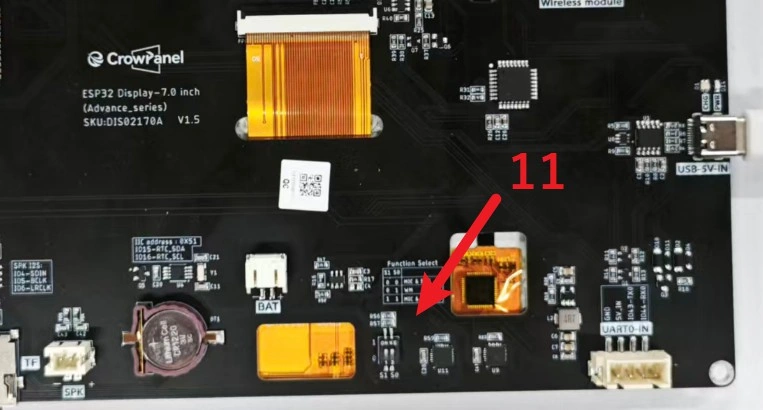
This lesson requires a TF/SD card. Please set the large-format board's function DIP switch to 11 = MIC&TF Card. DIP switch mapping for the large-format board: 00 = MIC&SPK, 01 = WM (wireless module), 11 = MIC&TF Card.
2. Learning Objectives
- Be able to prepare
800 x 480, 24-bit, uncompressed BMP images. - Be able to place
1.bmpthrough5.bmpin the root directory of the TF/SD card. - Be able to understand the SD SPI pinout and the mounting process.
- Be able to understand the workflow of loading image data into PSRAM and then displaying it on the screen.
- Be able to troubleshoot SD card mount failures, incorrect image dimensions, and garbled screen output.
3. Required Materials
- CrowPanel Advance 4.3-inch / 5.0-inch / 7.0-inch ESP32-S3 HMI.
- TF/SD card and a card reader.
- 5
800 x 480, 24-bit, uncompressed BMP images. - Name the images
1.bmp,2.bmp,3.bmp,4.bmp,5.bmpand place them in the root directory of the TF/SD card. - VS Code environment with ESP-IDF
5.5.4installed. - Local project:
4.3_5.0_7.0_IDF_Code/Lesson05-SD_images.
Code and Resource Download
Code download: - Lesson05-SD_images
Resource download:
4. ESP-IDF Software Operation Steps
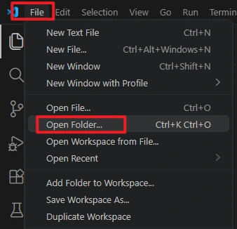
Open this lesson's project in VS Code:
4.3_5.0_7.0_IDF_Code/Lesson05-SD_images
Confirm the ESP-IDF version is 5.5.4 and the target chip is esp32s3.

Click Build to compile the project.
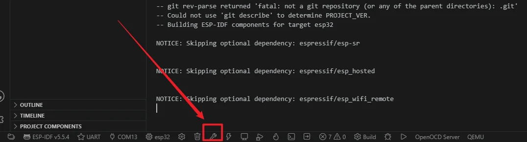
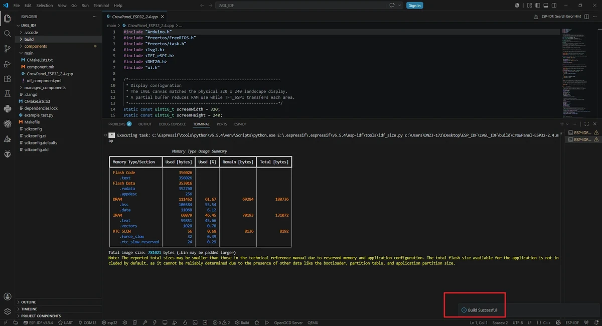
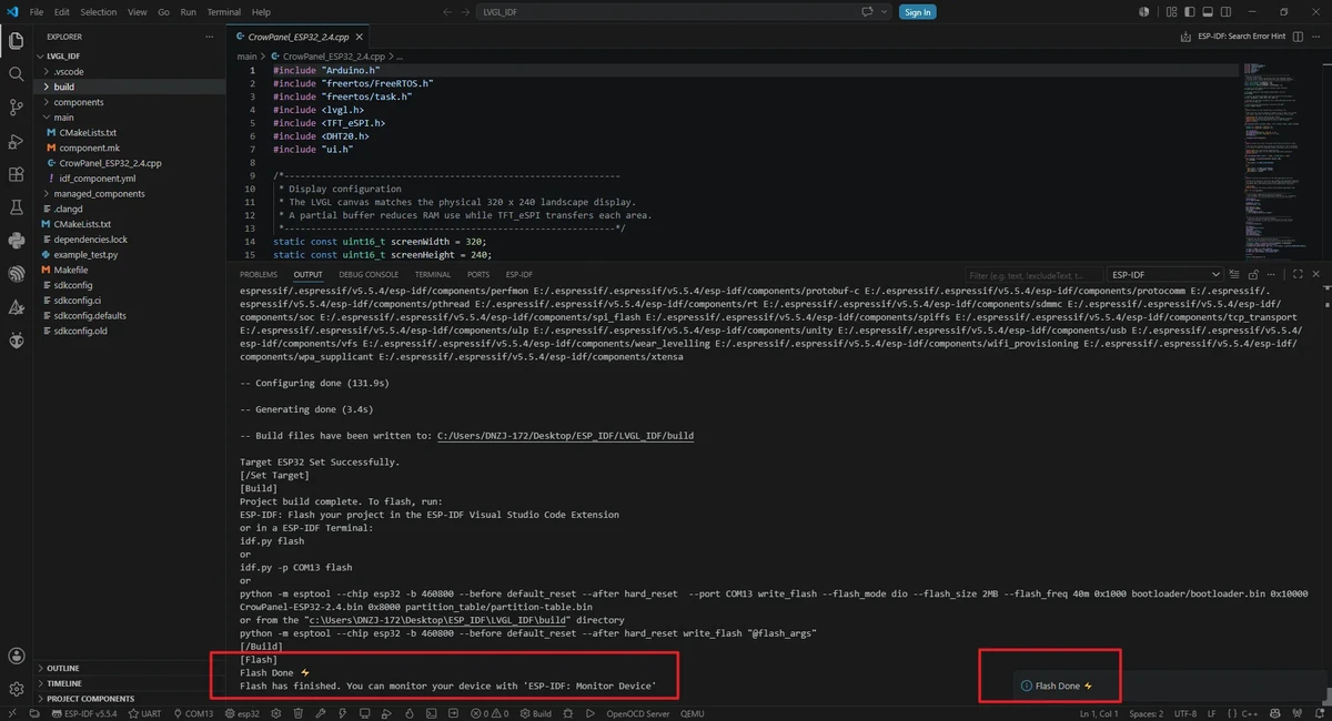
Select the correct serial port, then click Flash to flash the firmware.
5. Hardware Operation Steps
- Set the function DIP switch to
11 = MIC&TF Card. - Use a computer to copy
1.bmpthrough5.bmpto the root directory of the TF/SD card. - Insert the TF/SD card into the development board's card slot.
- Connect the development board to the computer using a USB data cable.
- After flashing the program, wait for the screen to display
SD Card OKand the image loading prompt. - Once image loading is complete, the screen switches to a new image every 5 seconds.
6. Key Code Explanation
The core code for this lesson is located in Lesson05-SD_images/main/SD_Display_Images_70_50_43.cpp.
6.1 Resolution and SD Pins
#define LCD_H_RES 800
#define LCD_V_RES 480

#define SD_MOSI 6
#define SD_MISO 4
#define SD_SCK  5
#define SD_CS   0
This lesson reads images at 800 x 480 for the large-format display. The SD card uses SPI communication, with pins MOSI=GPIO6, MISO=GPIO4, SCK=GPIO5, CS=GPIO0.
6.2 Image File Names
The TF/SD card root directory must contain files with matching names. If the file names do not match, the serial monitor will output "Failed to open file".
6.3 Image Size Requirements
The pixel data of a single 800 x 480, 24-bit BMP image is approximately 800 * 480 * 3 bytes. The project reads 24-bit uncompressed BMP files. If the image dimensions, bit depth, or compression format do not match, you may encounter a garbled display, color anomalies, or loading failures.
The figure below is for illustration purposes. Please adjust the appropriate resolution according to the different sizes you are actually using.
-
(Resolution for 4.3-inch, 5.0-inch, and 7.0-inch screens: 800x480)
-
(Resolution for 3.5-inch screen: 480x320)
-
(Resolution for 2.4-inch and 2.8-inch screens: 320x240)
6.4 PSRAM Image Cache
imageSlots[i] = (uint8_t*)heap_caps_malloc(
    IMAGE_PIXEL_BYTES,
    MALLOC_CAP_SPIRAM | MALLOC_CAP_8BIT
);
The project allocates a cache in PSRAM for each of the 5 images. This way, once the images are loaded, the slideshow does not need to repeatedly read from the TF/SD card during playback, making display switching more stable.
6.5 SD Card Initialization
SD_SPI.begin(SD_SCK, SD_MISO, SD_MOSI);
if (!SD.begin(SD_CS, SD_SPI, 40000000)) {
  Serial.println("SD mount failed");
}
If initialization fails, first check whether the DIP switch is set to 11 = MIC&TF Card, whether the card is seated firmly, whether the file system is healthy, and whether the CS pin is GPIO0. If necessary, lower the SPI frequency to troubleshoot signal stability.
6.6 Image Display
The image cache is pushed to the screen in RGB888 format. presentImage() uses kImageRotation = 2 to adapt the image orientation. If the orientation is wrong after you replace the assets later, prioritize checking the image orientation and this rotation parameter.
7. Image Asset Preparation Steps
- Prepare 5 landscape images.
- Crop or resize the images to
800 x 480. - Save them as 24-bit, uncompressed BMP.
- Rename the files to
1.bmpthrough5.bmp. - Place them in the root directory of the TF/SD card; do not place them in subfolders.
Image asset reference link: source material/800_480
8. Experimental Results
- The serial monitor outputs "SD mounted" and the card capacity.
- The serial monitor lists the files in the TF/SD card root directory.
- The screen first displays
SD Card OK, then displays "Loading images". - The screen displays
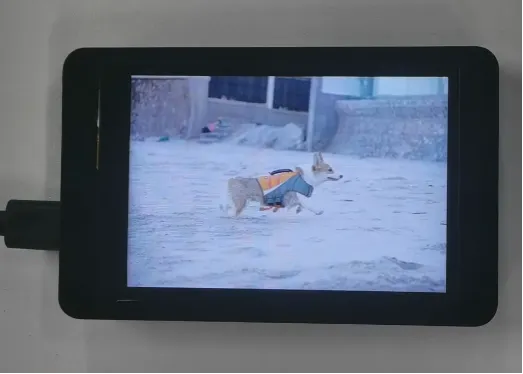
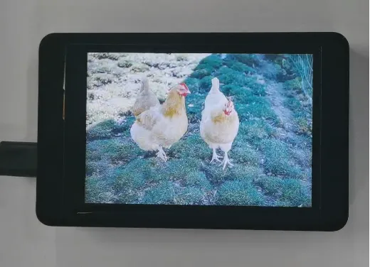
1.bmpthrough5.bmpin a loop. - Each image stays on screen for about 5 seconds.
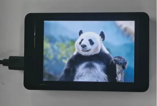
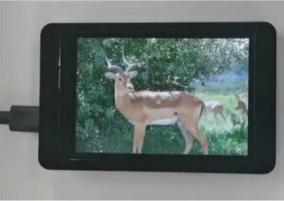
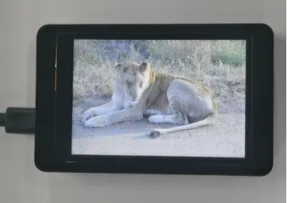
If SD Card Failed is displayed or image loading fails, check in order: whether the DIP switch is set to 11 = MIC&TF Card, whether the TF/SD card is recognized by the computer, whether the images are in the root directory, whether the file names match exactly, and whether the images are 800 x 480, 24-bit, uncompressed BMP.
9. Code Download
GitHub code link:
Resource download: