Lesson 02: UART1 Interface LED Control
1. Course Introduction
Treat the LED on the UART1 interface as a regular GPIO, and use high and low logic levels to achieve a cycle of 1 second on and 1 second off.
2. Learning Objectives
After completing this lesson, you should be able to:
- Understand the GPIO output mode and the current-sinking connection of the LED.
- Use
pinMode(),digitalWrite(), and the blockingdelay(). - Locate the UART1 LED based on the pin macro defined in
config.h.
3. What You Need to Prepare
- Prepare the CrowPanel Advanced 5-inch ESP32-P4 HMI AI Display development board and a data-capable USB-C cable, in the quantities required for this lesson.
- The UART1 interface on the board is labeled
UART, and the LED uses GPIO48. - The
config.hfile and the.inofile in the project must be placed in the same project directory.
Code reference: https://github.com/Elecrow-RD/-CrowPanel-Advanced-5inch-ESP32-P4-HMI-AI-Display-800x480-IPS-Touch-Screen/tree/master/example/V1.0
4. Software Operation Steps
Double-click to open the lesson 2 code. (.ino file)

Configure the options as described below.
- Board:
ESP32P4 Dev Module - Core Debug Level:
Info - Flash Frequency / Mode / Size:
80MHz/QIO/16MB (128Mb) - Partition Scheme:
16M Flash (3MB APP/9.9MB FATFS) - PSRAM:
Enabled - USB Mode:
Hardware CDC and JTAG - Port: After connecting the USB data cable to the UART0 port of the development board, select the newly appeared COM port under "Tools → Port".

5. Hardware Operation Steps
5.1 Identify Hardware and Safety Boundaries
Now that the code is ready, we need to flash the ESP32-P4 to see the results in action.
Connect a data-capable USB-C cable to the interface labeled UART0 on the development board, then connect it to the computer.

If you want to control the LED, you need to switch this switch to the left side of UART1
Then, switch the toggle switch on the 5-inch Advance-P4 to the UART1 position. Only in this way can the UART1 interface be used.

This is the design on the hardware side.

Switch to UART1 port:
Among the three interfaces shown in the figure, only the UART1 interface can be used at this time.
Alternatively, the expansion header at the bottom can also be used.
That is, either the UART1 interface or the expansion header can be used, but not both.
Switch to Wireless Module port:
Among the three interfaces shown in the figure, only the wireless module can be used at this time.
Alternatively, the expansion header at the bottom can also be used.
That is, either the wireless module or the expansion header can be used, but not both.
Summary:
The UART1 interface and the Wireless Module can only be used when switched to the corresponding port.
The expansion header at the bottom can be used regardless of the position of the mode switch, but it cannot be used simultaneously with the above interfaces. (When used simultaneously, only one of the three interfaces can be selected.)
After flashing is complete and the board is reset, observe whether the LED corresponding to GPIO48 lights up.

Continuously observe whether the LED blinks periodically at a rhythm of 1 second on and 1 second off; there should be no constant-on, constant-off, or irregular blinking.

5.2 Open the Project and Verify the Pins
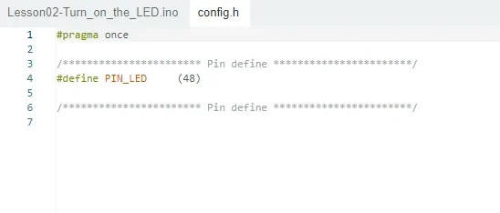
Open Lesson02-Turn_on_the_LED.ino and confirm that config.h exists in the same directory. This file centrally stores the hardware constants, making it easy to change pins without modifying the control logic.

5.3 Compile, Upload, and Observe
Before uploading the code, first select the upload configuration according to "4. Software Operation Steps".
Connect to UART0 and compile and upload using the general configuration; keep the development board powered on and observe the on/off cycle of the UART1 LED.

6. Key Code Explanation
6.1 GPIO Output and Timing Control
#include "board_config.h"

void setup() {
  pinMode(PIN_LED, OUTPUT);
}

void loop() {
  digitalWrite(PIN_LED, HIGH);
  delay(1000);
  digitalWrite(PIN_LED, LOW);
  delay(1000);
}
#include "board_config.h" imports the board pin definitions. In this file, PIN_LED is defined as GPIO48, so the application code can use the descriptive macro instead of writing the pin number directly.
pinMode(PIN_LED, OUTPUT) configures GPIO48 as an output;
digitalWrite(PIN_LED, HIGH) outputs a high level to turn the LED on, while digitalWrite(PIN_LED, LOW) outputs a low level to turn it off according to the current board circuit;
Each delay(1000) keeps the current LED state for 1000 ms. The two delays therefore produce a repeating cycle of 1 second on and 1 second off. This is a blocking delay, suitable for the demonstration in this lesson but not for complex concurrent control.
7. Observed Behavior
- The LED should stay on for 1 second, off for 1 second, and continue to loop.
8. Common Issues and Troubleshooting
- If the on/off logic is reversed, refer to the active-level macro defined in the board-level circuit.
- If the LED does not light up at all, check GPIO48, the interface orientation, and the power supply; do not arbitrarily switch to unknown pins.