Lesson 05: Touchscreen Coordinate Reading
1. Course Introduction
Initialize the ESP32-P4 display/touch panel, read GT911 touch points, and print the coordinates and touch strength to the serial monitor.
2. Learning Objectives
After completing this lesson, you should be able to:
-
Understand the panel initialization in
setup()and the multi-touch reading inloop(). -
Obtain reproducible X/Y coordinates when touching the screen.
-
Be able to compile and upload the project, and determine whether the hardware and program are functioning normally based on the experimental observations in this lesson.
3. What You Need to Prepare
-
Prepare the CrowPanel Advanced 5-inch ESP32-P4 HMI AI Display development board and a data-capable USB-C cable in the quantities required for this lesson.
-
The project directory must contain the
.inofile,board_config.h, and the configuration files provided by the project.
Code link reference: https://github.com/Elecrow-RD/-CrowPanel-Advanced-5inch-ESP32-P4-HMI-AI-Display-800x480-IPS-Touch-Screen/tree/master/example/V1.0
4. Software Operation Steps
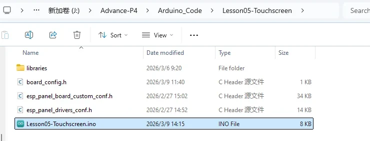
Double-click to open the Lesson 5 code (.ino file).
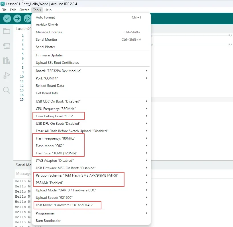
Configure the relevant options as described below.
- Board:
ESP32P4 Dev Module - Core Debug Level:
Info - Flash Frequency / Mode / Size:
80MHz/QIO/16MB (128Mb) - Partition Scheme:
16M Flash (3MB APP/9.9MB FATFS) - PSRAM:
Enabled - USB Mode:
Hardware CDC and JTAG - Port: After connecting the USB data cable to the development board's UART0, select the newly appeared COM port under "Tools → Port".
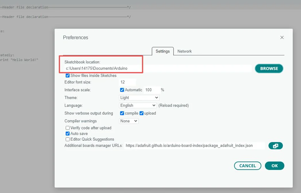
Following the library import steps explained in detail in Lesson 1, import the library files required for this project into the development environment to ensure the code can correctly locate the relevant dependencies during compilation, thereby guaranteeing that the program runs properly.
5. Hardware Operation Steps
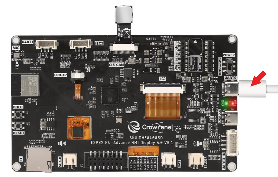
Connect a data-capable USB-C cable to the port labeled UART0 on the development board, then connect it to your computer. After connecting, the board's power indicator should light up, and the corresponding COM port should appear in the Arduino IDE.
Select the correct board and port in the Arduino IDE, then click Upload. After the upload completes and the board auto-resets, open the serial monitor and set the baud rate to 115200.
For details on how to open the serial monitor and how to set the baud rate, please refer to Lesson 1.
Gently touch different areas of the screen with your finger; do not use sharp objects. The serial monitor should continuously output the X and Y coordinates of the touch points.
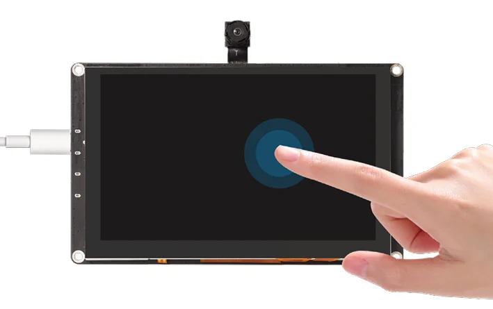
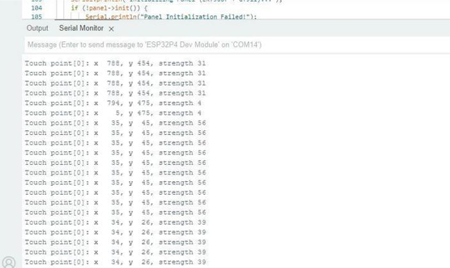
Touch the four corners and the center of the screen respectively, and confirm that the direction of coordinate change matches the touch position. If the coordinates are fixed or the direction is abnormal, check the touch ribbon cable, I2C configuration, and screen orientation parameters.
6. Key Code Explanation
6.1 Panel Initialization
    panel = new esp_panel::board::Board();

    // Initialize the bus and the devices (ST7265 & GT911)
    // The library uses settings from ESP_Panel_Conf.h internally
    Serial.println("Initializing Panel (ST7265 + GT911)...");
    if (!panel->init()) {
        Serial.println("Panel Initialization Failed!");
        while (1) delay(100);
    }

    // Begin the panel (Startup sequences and backlight)
    if (!panel->begin()) {
        Serial.println("Panel Start Failed!");
        while (1) delay(100);
    }
panel = new esp_panel::board::Board() creates the board object using the settings in the local configuration headers. panel->init() initializes the ST7265 display bus, LCD, and GT911 touch controller; panel->begin() starts the panel and backlight. A failed return value is logged and enters an intentional halt loop so later touch reads cannot run on an uninitialized device.
6.2 Multi-Touch Reading
ESP_PanelTouchPoint point[10];
int point_num = touch->readPoints(point, 10, 0);
for (int i = 0; i < point_num; ++i) {
  Serial.printf("Touch point[%d]: x %4d, y %3d, strength %d\n", i, point[i].x, point[i].y, point[i].strength);
}
ESP_PanelTouchPoint point[10] provides storage for up to ten contacts. touch->readPoints(point, 10, 0) writes the current contacts and returns their count; the loop then prints each point's X, Y, and strength. The main loop delays briefly between polls so the CPU is not saturated.
7. Experimental Observations
- While touching, the serial port continuously prints coordinates; after release, no new touch points are generated.
8. Common Issues and Troubleshooting
-
If
IDLE loopis continuously output, check the GT911 power supply, I2C pin macros, and panel configuration. -
If the coordinate axis direction is abnormal, first confirm the project's rotation/mapping configuration.