Lesson 14: SX1262 Wireless Module: LoRa Transceiver
1. Course Introduction
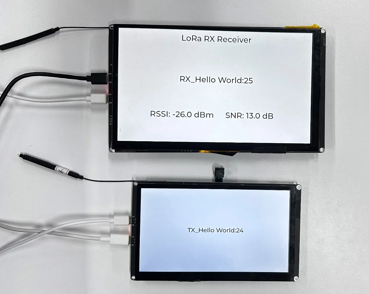
In this lesson, we will use the Arduino IDE to drive the SX1262 LoRa module via the SPI interface and the RadioLib library to implement point-to-point wireless data transmission and reception. The lesson includes two projects—a transmitter (TX) and a receiver (RX)—requiring two ESP32-P4 development boards to be used as a pair. The TX board sends an incrementing counter data packet TX_Hello World:N every second and displays the counter value on the screen; upon receiving a data packet, the RX board displays the counter value of RX_Hello World:N on the screen, along with the RSSI and SNR values. After flashing the program, the TX board's screen shows a white background with black text "TX_Hello World:N", with the number incrementing once per second; the RX board's screen displays the "RX_Hello World:N" counter, which increases each time data is received, and shows RSSI and SNR in real time. Through this experiment, learners will complete a full wireless communication link verification, covering SPI bus configuration, SX1262 LoRa initialization, interrupt-driven transmit/receive operations, and real-time LVGL display.
2. Learning Objectives
After completing this lesson, you should be able to:
- Understand the responsibilities of the TX/RX ends and the fully consistent LoRa parameters.
- Be able to explain the SX1262 SPI connections (SCK/MISO/MOSI/NSS/IRQ/NRST/BUSY) and the function of each pin.
- Be able to explain the meaning of the LoRa parameters (frequency 915 MHz, BW 125 kHz, SF7, CR7).
- Be able to complete compilation and flashing of both boards, and observe the TX count incrementing, the RX count incrementing with reception, and real-time RSSI/SNR updates.
3. Prerequisites
- Hardware: Two CrowPanel Advanced 5-inch ESP32-P4 HMI AI Display development boards; two USB Type-C data cables that support data transfer; two SX1262 LoRa modules, with one module connected to each development board.
Code reference: https://github.com/Elecrow-RD/-CrowPanel-Advanced-5inch-ESP32-P4-HMI-AI-Display-800x480-IPS-Touch-Screen/tree/master/example/V1.0
4. Software Operation Steps
Double-click to open the Lesson 14 code. (.ino file)
(There are two code files here, one for transmitting and one for receiving.)


After opening the code, go to bsp_wireless.h first and enable the definitions related to the SX1262 module used in this lesson.

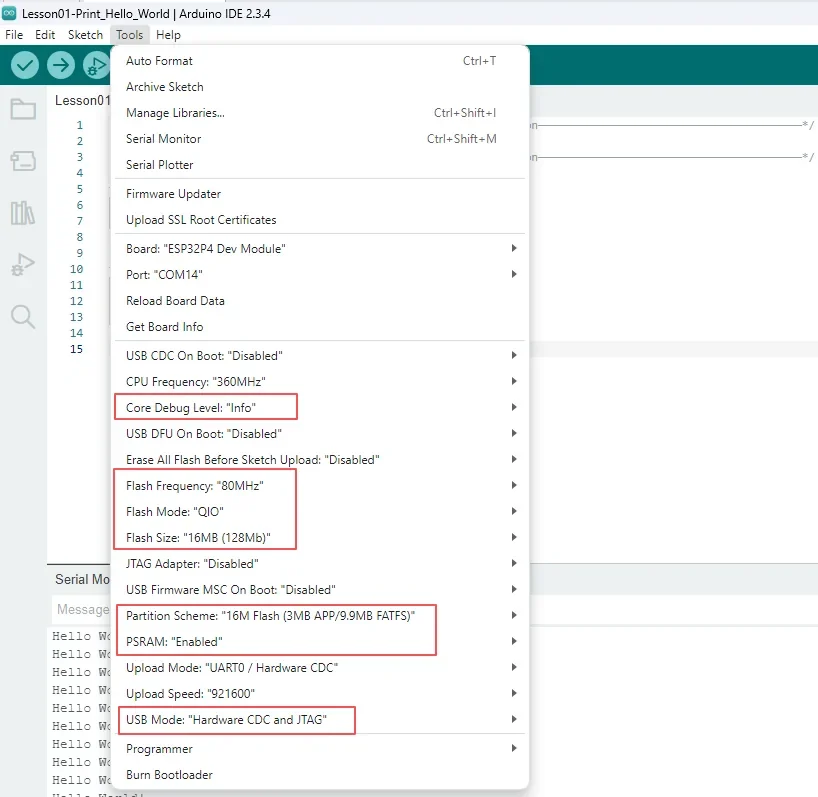
Configure the options as follows.
- Board:
ESP32P4 Dev Module - Core Debug Level:
Info - Flash Frequency / Mode / Size:
80MHz/QIO/16MB (128Mb) - Partition Scheme:
16M Flash (3MB APP/9.9MB FATFS) - PSRAM:
Enabled - USB Mode:
Hardware CDC and JTAG - Port: After connecting the USB data cable to the development board's UART0, select the newly appeared COM port under "Tools → Port".
Follow the library import steps explained in detail in Lesson 1 to import the library files required by this project into the development environment, ensuring that the relevant dependencies can be correctly located during compilation, so as to guarantee proper program operation.

5. Hardware Operation Steps
With the power off, connect the SX1262 module and antenna to each of the two development boards, confirming the module orientation, pins, and LCD ribbon cable are correct. Use the UART0 data cable to connect both development boards to the computer; if necessary, add auxiliary power via the USB 2.0 interface.

Switch the mode switch on both development boards to the Wireless Module position so that the SPI and control signals are connected to the wireless module slot.
Then, switch the toggle switch on the 5-inch Advance-P4 to the Wireless Module position.
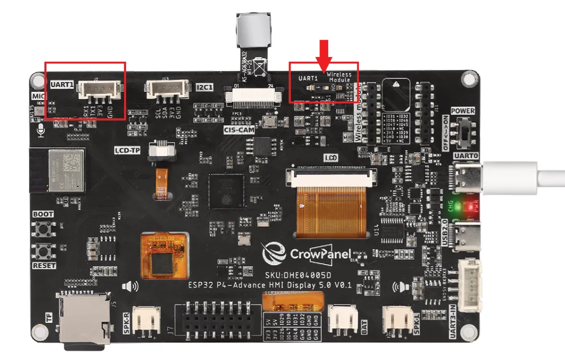
This is the design on the hardware side.

Switch to UART1 port:
Among the three interfaces shown in the figure, only the UART1 interface can be used at this time.
Alternatively, the expansion header at the bottom can also be used.
That is, either the UART1 interface or the expansion header can be used, but not both.
Switch to Wireless Module port:
Among the three interfaces shown in the figure, only the wireless module can be used at this time.
Alternatively, the expansion header at the bottom can also be used.
That is, either the wireless module or the expansion header can be used, but not both.
Summary:
The UART1 interface and the Wireless Module can only be used when switched to the corresponding port.
The expansion header at the bottom can be used regardless of the position of the mode switch, but it cannot be used simultaneously with the above interfaces. (When used simultaneously, only one of the three interfaces can be selected.)
In the Arduino IDE, open the TX and RX projects separately, select each board's respective UART0 COM port, and click Upload. After uploading completes, open the serial monitor at a baud rate of 115200 for each board.
For how to open the serial monitor and how to set the baud rate, please refer to Lesson 1 in detail.
After the TX board resets, the screen should display TX_Hello World:0, with the counter increasing by approximately 1 per second; the serial port outputs the transmitted data synchronously.
After the RX board resets, the screen should display the reception interface and the initial counter.

Place the two boards at a relatively close distance and confirm that the RX counter increments with the TX data and displays RSSI and SNR in real time. If reception fails, check whether the frequency, bandwidth, spreading factor, coding rate, and sync word are consistent at both ends.
6. Key Code Explanation
6.1 Wireless Initialization and Transmission Task
  sx1262_tx_init();
  xTaskCreatePinnedToCore(ui_counter_task, "ui_counter", 4096, NULL,
                                configMAX_PRIORITIES - 5, NULL, 0);

    xTaskCreatePinnedToCore(lora_tx_task, "sx1262_tx", 8192, NULL,
                                configMAX_PRIORITIES - 5, NULL, 1);

    MAIN_INFO("Tasks created, starting synchronized transmission...");

    delay(100);  // Wait lvgl run, Prevent the screen from flickering
    stc8_set_pwm_duty(STC8_PWM_LCD_BL_EN, 100);     // set backlight (0~100)
setup() retries sx1262_tx_init() until the radio is ready, then creates a UI counter task pinned to core 0 and lora_tx_task pinned to core 1 with the same priority. The TX task increments the shared counter and transmits on its periodic schedule. After task creation the sketch waits briefly for LVGL, sets the LCD backlight PWM to 100%, and reports synchronized transmission startup.
6.2 RX Callback and LVGL
//  (Set callback function for received data)
    sx1262_set_rx_callback(rx_data_callback);  // Register LoRa RX callback function
    MAIN_INFO("RX callback registered");  // Log callback registration success

    // (Create LoRa receiving task)
    xTaskCreatePinnedToCore(lora_rx_task, "sx1262_rx", 4096, NULL,
                            configMAX_PRIORITIES - 5, NULL, 1);  // Create FreeRTOS task pinned to core 1

    MAIN_INFO("LoRa RX receiver started, waiting for data...");  // Log start message

    delay(100);  // Wait lvgl run, Prevent the screen from flickering
    stc8_set_pwm_duty(STC8_PWM_LCD_BL_EN, 100);     // set backlight (0~100)
setup() registers rx_data_callback, whose current signature receives the payload length plus RSSI and SNR, then creates lora_rx_task pinned to core 1. The callback increments the packet counter and updates the LVGL receive display only while the LVGL lock is held. A short startup delay precedes the full-brightness backlight setting, confirming that the receiver is ready.
7. Experimental Observations
-
The TX counter increases by approximately 1 per second; the RX displays the corresponding message and increments only after receiving real data.
-
The RX can display RSSI/SNR, and the values vary with distance, obstruction, and antenna orientation.
8. Common Issues and Troubleshooting
- When there is no data, sequentially check the module orientation, SPI/CS/RST/IRQ/BUSY pins, frequency/bandwidth/spreading factor/coding rate, antenna, and the code branches at both ends.
- If the device restarts during operation, first provide independent power to the USB 2.0 port.