Lesson 15: nRF24L01 Wireless RF Module: 2.4 GHz Transceiver
1. Course Introduction
This course uses the Arduino IDE to drive the nRF24L01 wireless module via the SPI interface and the RadioLib library, implementing point-to-point data transmission and reception. The course includes two projects: TX (transmit) and RX (receive), requiring two ESP32-P4 development boards paired for use. The TX board sends an incrementing counter data packet NRF24_TX_Hello World:N every second and displays the counter value on the screen; upon receiving data, the RX board displays the counter value of NRF24_RX_Hello World:N on the screen. Compared with the LoRa in Lesson 14, the nRF24L01 operates in the 2.4 GHz ISM band and uses GFSK modulation, offering a higher transmission rate but a shorter communication distance. After the program is flashed, the screens of both boards display the transmission and reception counts in real time. Through this experiment, learners will complete verification of a full wireless communication link, covering SPI configuration, nRF24L01 initialization, transceiver address matching, and LVGL display functionality.
2. Learning Objectives
After completing this lesson, you should be able to:
- Describe the SPI wiring of the nRF24L01 (SCK/MISO/MOSI/CS/CE/IRQ) and the function of each pin.
- Explain why communication requires the TX and RX pipe addresses to be identical in order to function normally.
- Complete compilation and flashing of both boards, and observe the TX counter incrementing and the RX counter incrementing when data is received.
- Determine whether address matching and the wireless link are working properly based on whether the RX successfully receives data.
3. Preparations
- Hardware: CrowPanel Advanced 5-inch ESP32-P4 HMI AI Display development board × 2; two USB Type-C data cables that support data transfer; two nRF24L01 modules, with one module connected to each development board.
Code reference link: https://github.com/Elecrow-RD/-CrowPanel-Advanced-5inch-ESP32-P4-HMI-AI-Display-800x480-IPS-Touch-Screen/tree/master/example/V1.0
4. Software Operation Steps
Double-click to open the Lesson 15 code (.ino file).
(There are two sets of code here, one for transmission and one for reception)


After opening the code, first go to bsp_wireless.h and enable the definitions related to the nRF2401 module used in this lesson.

Configure the relevant options as follows.
- Board:
ESP32P4 Dev Module - Core Debug Level:
Info - Flash Frequency / Mode / Size:
80MHz/QIO/16MB (128Mb) - Partition Scheme:
16M Flash (3MB APP/9.9MB FATFS) - PSRAM:
Enabled - USB Mode:
Hardware CDC and JTAG - Port: After connecting the development board's UART0 via a USB data cable, select the newly appeared COM port under "Tools → Port".

Follow the library import steps explained in detail in Lesson 1 to import the library files required by this project into the development environment, ensuring that the code can correctly locate the relevant dependencies during compilation, thereby guaranteeing the program runs normally.

5. Hardware Operation Steps
With power off, connect the nRF24L01 module and antenna to both development boards respectively, and confirm the module orientation, pins, and LCD ribbon cable are correct. Connect both boards to the computer using the UART0 data cable; if necessary, add auxiliary power via the USB 2.0 interface.

Switch the mode switch of both development boards to the Wireless Module position so that the SPI and control signals connect to the wireless module slot.
Then, switch the toggle switch on the 5-inch Advance-P4 to the Wireless Module position.
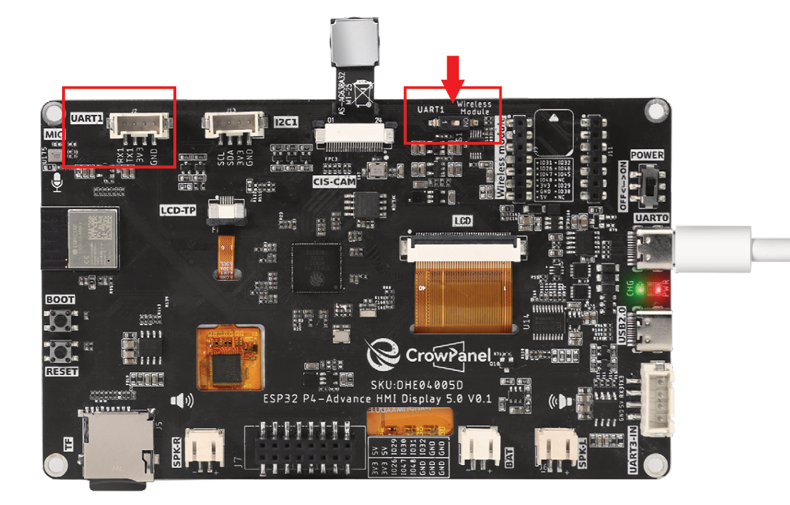
This is the design on the hardware side.

Switch to UART1 port:
Among the three interfaces shown in the figure, only the UART1 interface can be used at this time.
Alternatively, the expansion header at the bottom can also be used.
That is, either the UART1 interface or the expansion header can be used, but not both.
Switch to Wireless Module port:
Among the three interfaces shown in the figure, only the wireless module can be used at this time.
Alternatively, the expansion header at the bottom can also be used.
That is, either the wireless module or the expansion header can be used, but not both.
Summary:
The UART1 interface and the Wireless Module can only be used when switched to the corresponding port.
The expansion header at the bottom can be used regardless of the position of the mode switch, but it cannot be used simultaneously with the above interfaces. (When used simultaneously, only one of the three interfaces can be selected.)
In the Arduino IDE, open the TX and RX projects separately, select the respective UART0 COM port for each board, and click Upload. After the upload completes, open the serial monitor at 115200 baud for each.
For how to open the serial monitor and how to set the baud rate, please refer to Lesson 1 in detail.
After the TX board resets, the screen should display NRF24_TX_Hello World:0, with the count incrementing approximately once per second; the serial port displays the transmission completion message.
After the RX board resets, the screen should display the reception interface and the initial count.

Place both boards at a relatively close distance and confirm that the RX count increments along with the TX data. If there is no data, check whether the address, channel, rate, CRC, and payload length at both ends are consistent.
6. Key Code Explanation
6.1 TX Periodic Transmission
    TickType_t last_wake_time = xTaskGetTickCount();
    const TickType_t frequency = pdMS_TO_TICKS(1000); // 1 second = 1000ms

    while (1) {
        // Increment the TX counter exactly once per second
        nrf24_inc_tx_counter();
        bool nrf24_tx_OK = false;
        nrf24_tx_OK = send_nrf24_pack_radio();
        if (nrf24_tx_OK != true) {
            MAIN_ERROR("nRF24L01 TX failed");
        }

        vTaskDelayUntil(&last_wake_time, frequency);
    }
setup() retries nrf24_tx_init() until the nRF24L01 is ready, then starts ui_counter_task on core 0 and nrf24_tx_task on core 1. The TX task increments the shared counter, calls send_nrf24_pack_radio(), logs a failure when the send result is false, and uses vTaskDelayUntil() to maintain an exact one-second period. The UI task reads the same counter only while holding the LVGL lock.
6.2 RX Callback and Pipe Address
setup() registers rx_data_callback with nrf24_set_rx_callback() and creates nrf24_rx_task on core 1. The callback now accepts only the received buffer and length, increments the packet count, and updates the LVGL label under the LVGL lock. nrf24_rx_init() applies the radio channel, data rate, power, address width, and pipe configuration; both ends must use matching pipe addresses or no packets will be delivered.
7. Experimental Phenomena
-
The TX transmits approximately once per second, and the RX increments
NRF24_RX_Hello World:ionly when it actually receives data. -
After disconnecting the TX, the RX should not increment continuously on its own.

8. FAQ and Troubleshooting
- When there is no data, check the 2.4 GHz parameters, channel, rate, 5-byte pipe address, CE/CSN/SPI wiring, and power supply.
- Confirm that both ends have enabled the same nRF24 wireless branch.