5inch_P4_IDF_02_Turn_On_LED: Lighting Up the Onboard LED with ESP32-P4
1. Course Introduction
In this lesson, we use ESP-IDF to drive and light up the onboard LED of the ESP32-P4 development board through GPIO. After the program is flashed, the board resets on power-up, and the LED blinks continuously at a rhythm of 1 second on and 1 second off. Learners only need to connect a USB data cable, set the target chip, compile, and flash to observe the periodic blinking of the LED.
This lesson is a beginner's course on peripheral driving. Building on the environment configuration basics from Lesson01, it introduces GPIO output configuration and FreeRTOS task creation for the first time. Through this experiment, learners will complete an introductory verification of GPIO initialization, level control, and task scheduling, laying the foundation for driving peripherals such as screen backlight and sensors in later lessons.
2. Learning Objectives
- Be able to open the Lesson02 project in ESP-IDF and set the target chip to
esp32p4. - Be able to explain the meaning of each parameter when
gpio_configconfigures GPIO48 as an output. - Be able to explain the role of the stack size and priority parameters when
xTaskCreatecreates a task. - Be able to complete compilation and flashing, and observe whether the LED blinks at a 1-second cycle.
- Be able to determine whether the GPIO configuration and task are running normally based on whether the LED blinks.
3. Preparation
- Compatible development board: CrowPanel Advanced 5-inch ESP32-P4 HMI AI Display Development Board.
- Software: VS Code, ESP-IDF Extension (ESP-IDF v5.4 and above). This lesson uses ESP-IDF v5.5.4.
- Project dependencies: Keep the
main/main.cfile and theperipheral/bsp_extracomponent under theLesson02-Turn_on_the LEDdirectory; no additional components need to be installed. - Configuration: target chip
esp32p4.
Code download link:
4. Software Operation Steps
The operations in this section follow the basic ESP-IDF flow from Lesson 1. Please first confirm that ESP-IDF v5.5.4, the UART flashing method, the actual serial port, and the target chip esp32p4 are correctly set, then follow the images below to check the project, components, configuration, and running results item by item.
In File Explorer, locate this lesson's project directory, right-click and select to open it with VS Code;

After opening, confirm that the project name in the window matches this lesson.

First, select the code runtime environment ESP-IDF v5.5.4, set the flashing method to UART, then select the serial port that actually corresponds to the development board. Then, in the ESP-IDF Extension panel, click Set Espressif Device Target and select esp32p4.
After the setup is complete, the status bar should display ESP-IDF v5.5.4, UART, the required COM port, and ESP32-P4.

Click SDK Configuration Editor in the VS Code bottom status bar or the ESP-IDF extension panel, and wait for the configuration page to fully load before modifying parameters. If the page is still loading, do not immediately execute Build.


In the search box, enter flash and ensure Flash SPI mode: QIO; Flash Sampling Mode: STR Mode; Flash SPI speed: 80 MHz; Flash size: 16 MB. These parameters should be consistent with the onboard Flash of the Advance-P4.

After checking that the configuration is correct, click Save in the upper-right corner; confirm that the modifications are saved, then execute Build to compile.
Click Full Clean to clear the cache left over from the previous compilation. Performing this operation after the first compilation, switching project configurations, or modifying SDK parameters can prevent old configurations from affecting new compilation results.

Before compiling, check the GPIO48 initialization and blink task code again, then click Build. On success, the end of the output window shows Project build complete, with no errors.
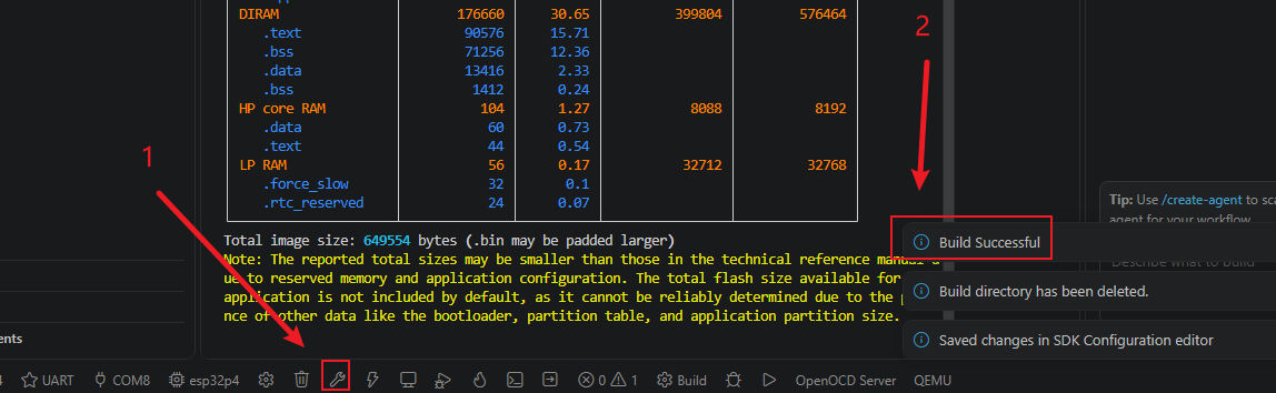
Confirm that the development board is connected to the computer via USB, then click Select Port to Use to select the corresponding serial port.
Click Flash to flash the firmware. After flashing is complete, the message Hard resetting... is displayed.
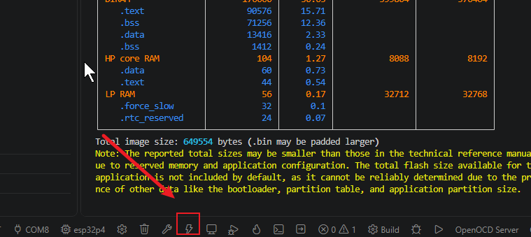
After flashing is complete, you can click Monitor to view the serial log and confirm whether the task was created normally. Press Ctrl + ] to exit the monitor.

Finally, you can use the one-click operation button in the ESP-IDF status bar to continuously execute compilation, flashing, and opening the serial monitor. Use this only after the project configuration, serial port, and code have all been confirmed correct; if you need to locate a problem, you should still follow the steps above item by item.

5. Hardware Operation Steps
Use a USB Type-C data cable that supports data transfer to connect the ESP32-P4 development board to the computer. After connecting, the board's power indicator should light up.

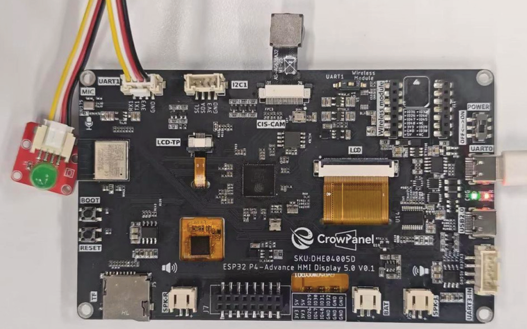
If you want to control the LED, you need to switch this switch to the left side of UART1
Then, switch the toggle switch on the 5-inch Advance-P4 to the UART1 position. Only in this way can the UART1 interface be used.

This is the design on the hardware side.

Switch to UART1 port:
Among the three interfaces shown in the figure, only the UART1 interface can be used at this time.
Alternatively, the expansion header at the bottom can also be used.
That is, either the UART1 interface or the expansion header can be used, but not both.
Switch to Wireless Module port:
Among the three interfaces shown in the figure, only the wireless module can be used at this time.
Alternatively, the expansion header at the bottom can also be used.
That is, either the wireless module or the expansion header can be used, but not both.
Summary:
The UART1 interface and the Wireless Module can only be used when switched to the corresponding port.
The expansion header at the bottom can be used regardless of the position of the mode switch, but it cannot be used simultaneously with the above interfaces. (When used simultaneously, only one of the three interfaces can be selected.)
After flashing is complete and the board is reset, observe whether the LED corresponding to GPIO48 lights up.

Continuously observe whether the LED blinks periodically at a rhythm of 1 second on and 1 second off; there should be no constant-on, constant-off, or irregular blinking.
6. Key Code Explanation
void led_blink_task(void *pvParameters)
{
    gpio_extra_init();

    while (1) {
        gpio_extra_set_level(1);
        vTaskDelay(1000 / portTICK_PERIOD_MS);
        gpio_extra_set_level(0);
        vTaskDelay(1000 / portTICK_PERIOD_MS);
    }
}
gpio_extra_init() initializes the onboard LED GPIO through the lesson BSP. The loop then drives the output high for one second and low for one second, producing a two-second blink period. Keeping the GPIO details inside bsp_extra lets the application use the board LED without repeating the pin configuration in main.c.
app_main() creates the blinking function as a FreeRTOS task with a 2048-byte stack and priority 5. Once scheduled, the task remains in its loop and controls the LED independently of the application entry function.
7. Experimental Observations
After the program is flashed and reset, the serial monitor displays the ESP-IDF startup information. Then led_blink_task is created and begins running, and the GPIO48 output level toggles once per second.
The LED should not exhibit constant-on, constant-off, or irregular blinking. If the LED stays on constantly, it may be that a vTaskDelay was deleted, or gpio_extra_set_level(0) was not executed; if the LED never lights up, you should first check whether the pin_bit_mask and mode in gpio_config are correct, and whether the LED is actually connected to GPIO48.