5inch_P4_IDF_03_UART3_IN_Interface: ESP32-P4 UART3-IN External Power Supply and Serial Port Interface Description
1. Course Introduction
This lesson introduces the UART3-IN interface on the CrowPanel Advanced 5-inch ESP32-P4 HMI AI Display development board. This lesson does not include any code, nor does it require opening VS Code, compiling, or flashing firmware. It builds on the LED blinking program already flashed in Lesson 2 to explain the power supply and serial communication functions of UART3-IN.
The UART0 interface is used to download programs and can also supply power to the board when connected to a computer; the UART3-IN can provide external power input to the board and can be used as a general-purpose serial port, but it cannot download programs. The two interfaces are located close to each other, so before use, confirm the interface label and purpose.
2. Learning Objectives
- Be able to locate the
UART0andUART3-INinterfaces on the development board. - Be able to explain the differences between
UART0andUART3-INin terms of program downloading and power supply. - Be able to power the development board via
UART3-INusing an adjustable DC power supply set to5Vand2A. - Be able to confirm that the external power supply is working properly by observing the LED blinking behavior from Lesson 2.
- Be able to explain why externally connected devices require independent power when UART3-IN is used as a general-purpose serial port.
3. What You Need
- Applicable development board: CrowPanel Advanced 5-inch ESP32-P4 HMI AI Display development board.
- One adjustable DC power supply, with the output voltage set to
5Vand the current limit set to2A. - Two Dupont wires, for connecting
VCCandGNDrespectively. - The LED blinking program already flashed in Lesson 2, used to verify the power supply result.
4. Hardware Operation Steps
Observe the UART0 and UART3-IN interfaces on the right side of the development board. UART0 is connected to the serial port flashing chip and can be used to download programs; after connecting UART0, the board's power indicator lights up, indicating that this interface can also supply power. UART3-IN does not have a serial port flashing chip, so it cannot be used to download programs.
At this point, you can see both the UART3-IN and UART0 interfaces. In the previous lesson, when we flashed the code, we learned that the UART0 pins are used to upload code. You can also observe that after connecting the UART0 interface, the power indicator next to it lights up, indicating that it can also supply power.

Confirm the functional differences between UART0 and UART3-IN. UART3-IN can serve as an external power input interface and can also be used for general-purpose serial communication; it cannot replace UART0 for program downloading.

Turn off the adjustable power supply output. Use two Dupont wires to connect to UART3-IN: connect the positive terminal of the power supply to VCC, and the negative terminal to GND. After confirming the wiring is correct, set the power supply output to 5V and the current limit to 2A, then turn on the power output.
Next, we return to the UART3-IN interface. This interface is similar in function to the UART0 interface discussed earlier. It can supply power but cannot upload code. The UART0 interface is connected to the serial port flashing chip, making code flashing relatively convenient. However, the UART3-IN interface does not have a serial port flashing chip. It can only be used for power supply and serial port operations. Therefore, we will now explain how the UART3-IN interface can be used to supply power. You need to prepare a power supply along with two Dupont wires. One wire connects the VCC pin of UART3-IN to the positive terminal of the power supply, and the other wire connects the GND pin of UART3-IN to the negative terminal of the power supply.
Note: The voltage and current used here are supplied by a programmable DC power supply. You only need to ensure that the externally supplied voltage is 5V and the current is 2A, then connect them to the corresponding VCC and GND pins on UART3-IN (connect the positive terminal to VCC and the negative terminal to GND). Verify that the wiring is correct, then turn on the power switch to supply power.
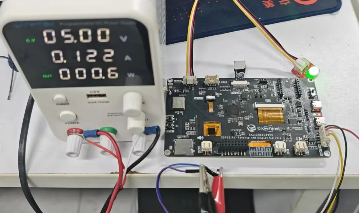
Observe whether the LED flashed in Lesson 2 continues to blink periodically. Normal LED blinking indicates that the UART3-IN external power supply is successful; if the LED does not light up or does not blink, immediately turn off the power and check the voltage, current limit, VCC/GND polarity, and wiring status.
5. Key Precautions
UART3-IN can only be used for external power input and general-purpose serial communication; it cannot be used for program downloading.
The external power supply must be set to 5V, with the positive terminal connected to VCC and the negative terminal connected to GND. Do not connect the power wires to RX3 or TX3.
When using UART3-IN as a general-purpose serial port, the externally connected device requires independent power; UART3-IN cannot supply power to the external device. Both communicating parties also need a common ground.
Before wiring, plugging/unplugging, or adjusting Dupont wires, turn off the external power supply. If a power anomaly occurs, disconnect power first and then troubleshoot, to avoid adjusting the wiring while energized.
6. Lesson Summary
UART0 is connected to the serial port flashing chip and can be used for program downloading and power supply; UART3-IN can be used as a 5V external power input and a general-purpose serial port, but it does not have program downloading capability. By using an external power supply together with the LED blinking behavior from Lesson 2, you can complete verification of the UART3-IN power supply function.