5inch_P4_IDF_05_Touchscreen: ESP32-P4 I2C Touch GT911
1. Course Introduction
This lesson uses ESP-IDF to initialize the GT911 capacitive touchscreen controller via the I2C master driver, and reads touch coordinates through polling. After the program is flashed, the development board powers on and resets; the I2C bus (SDA=GPIO45, SCL=GPIO46) and the GT911 (RST=GPIO40, INT=GPIO42) complete initialization. When the learner touches the screen with a finger, the serial monitor prints the touch coordinates in real time as Touch at X=..., Y=..., and stops printing when the finger is lifted.
This lesson introduces the I2C bus and the touch driver for the first time, and serves as the foundation for subsequent lessons on lighting up the display and LVGL interaction. Through this experiment, learners will complete end-to-end verification of the full chain of I2C bus creation, device registration, GT911 initialization, and coordinate reading.
2. Learning Objectives
- Be able to open the Lesson05 project in ESP-IDF and set the target chip to
esp32p4. - Be able to explain the call order and roles of
i2c_new_master_bus,esp_lcd_new_panel_io_i2c, andesp_lcd_touch_new_i2c_gt911. - Be able to explain the fallback mechanism between the primary and backup I2C addresses of the GT911.
- Be able to complete compilation and flashing, and touch the screen to check whether coordinates are printed on the serial port.
- Be able to determine whether the I2C and touch link is functioning properly based on whether the coordinates change as the finger moves.
3. Prerequisites
- Supported development board: CrowPanel Advanced 5-inch ESP32-P4 HMI AI Display Development Board.
- Software: VS Code, ESP-IDF Extension (ESP-IDF v5.5.4 or later).
- Project dependencies: keep the
main/main.c,peripheral/bsp_i2c, andperipheral/bsp_displaycomponents, as well as theesp_lcd_touch_gt911managed component. - Configuration: target chip
esp32p4;
Code download link:
4. Software Operation Steps
The operations in this section follow the basic ESP-IDF workflow from Lesson 1. Please first confirm that ESP-IDF v5.5.4, the UART flashing method, the actual serial port, and the target chip esp32p4 are set correctly, then check the project, components, configuration, and running results item by item against the images below.
Locate this lesson's project directory in File Explorer, right-click and choose to open it with VS Code;
You need to open this lesson's code (Lesson 5); the image is for illustration only.
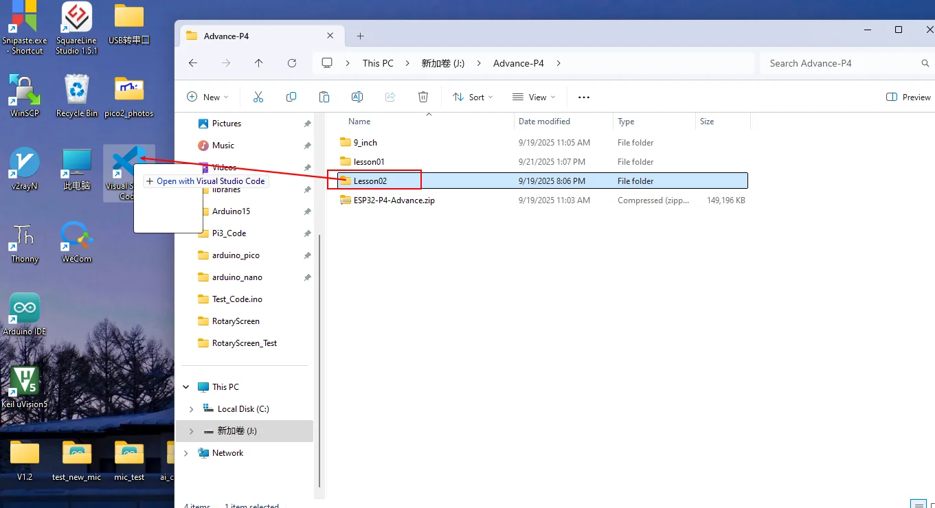
After opening, confirm that the project name displayed in the window matches this lesson.
First select the code execution environment ESP-IDF v5.5.4, set the flashing method to UART, and then select the serial port that actually corresponds to the development board. Next, in the ESP-IDF Extension panel, click Set Espressif Device Target and select esp32p4.
After the settings are complete, the status bar should display ESP-IDF v5.5.4, UART, the required COM port, and ESP32-P4.

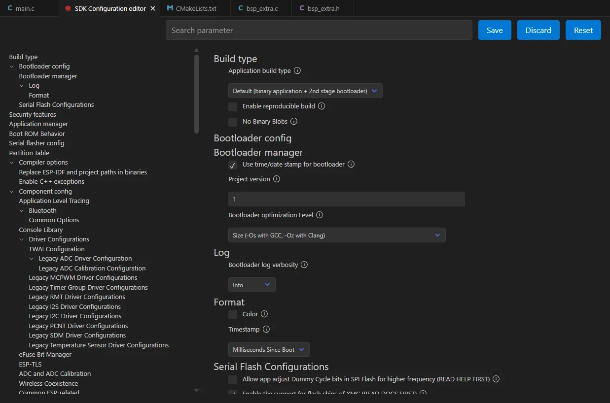
Click SDK Configuration Editor in the VS Code bottom status bar or the ESP-IDF extension panel, and wait for the configuration page to fully load before modifying parameters. If the page is still loading, do not execute Build immediately.

Enter flash in the search box and ensure Flash SPI mode: QIO; Flash Sampling Mode: STR Mode; Flash SPI speed: 80 MHz; Flash size: 16 MB. These parameters should be consistent with the onboard Flash of the Advance-P4.
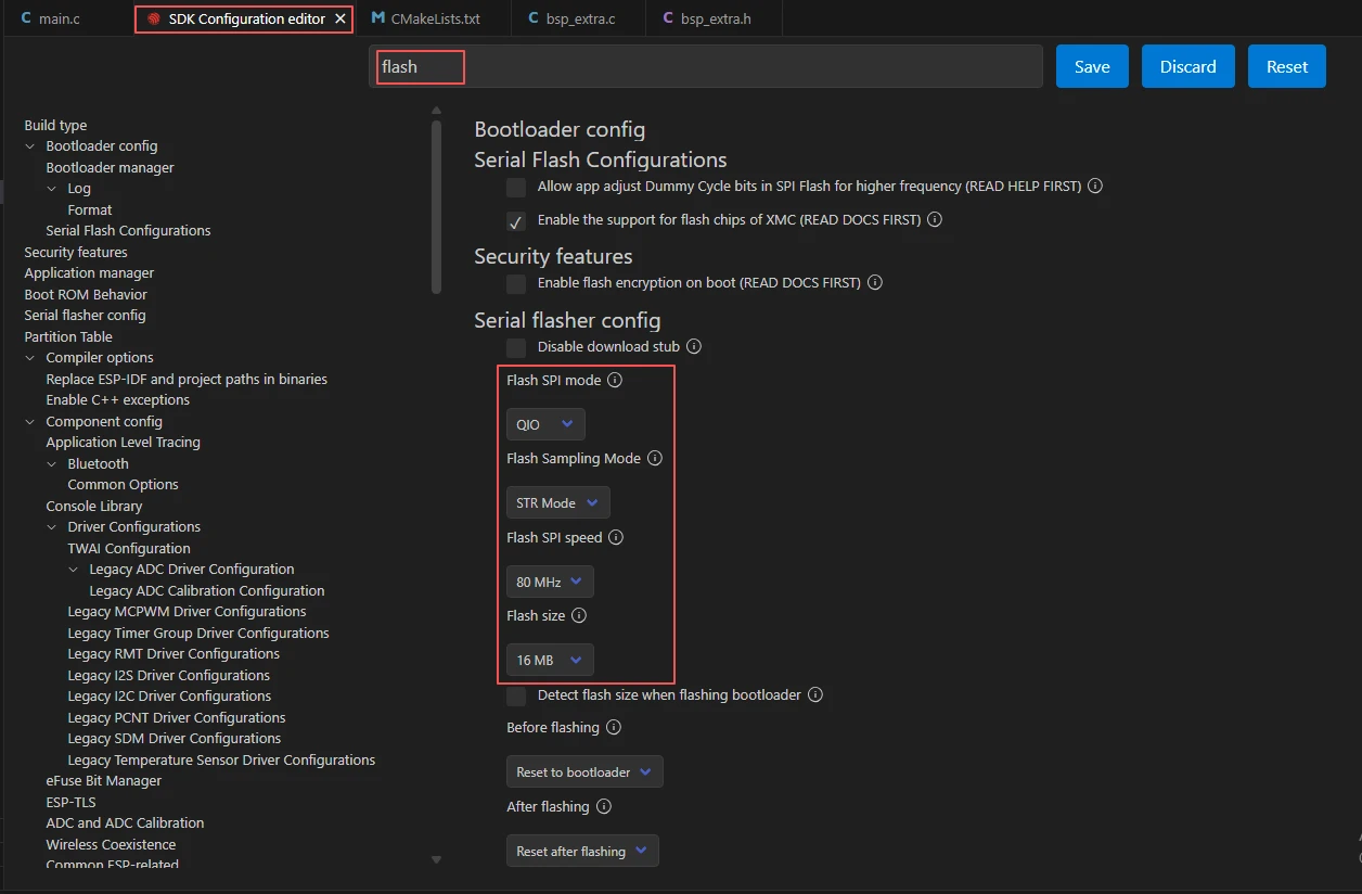
After checking that the configuration is correct, click Save in the upper-right corner; confirm that the changes have been saved, then execute Build to compile.
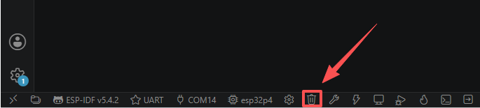
Click Full Clean to clear the cache left by the previous compilation. Performing this operation after the first compilation, switching project configurations, or modifying SDK parameters can prevent old configurations from affecting the new compilation result.
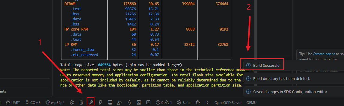
Then click Build.
Confirm that the development board is connected to the computer via USB, and click Select Port to Use to select the corresponding serial port.
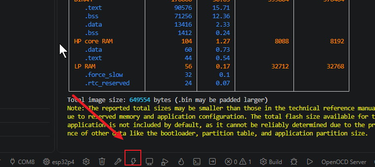
Click Flash to flash the firmware.
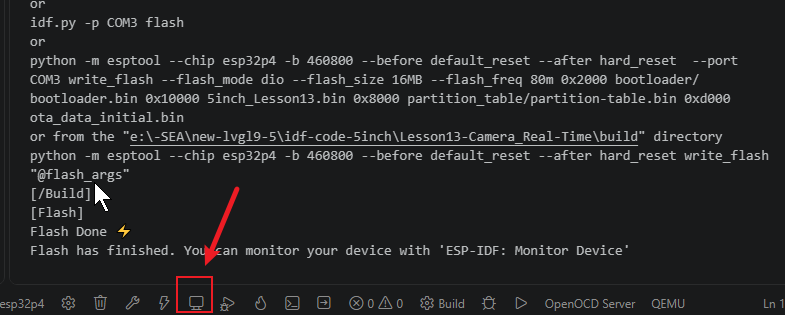
After flashing is complete, click Monitor to view the serial log and confirm whether the task was created successfully. Press Ctrl + ] to exit the monitor.
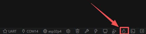
Finally, you can use the one-click operation button in the ESP-IDF status bar to continuously execute compilation, flashing, and opening the serial monitor. Use this only after the project configuration, serial port, and code have all been confirmed correct; if you need to locate a problem, you should still follow the steps above one by one.
5. Hardware Operation Steps
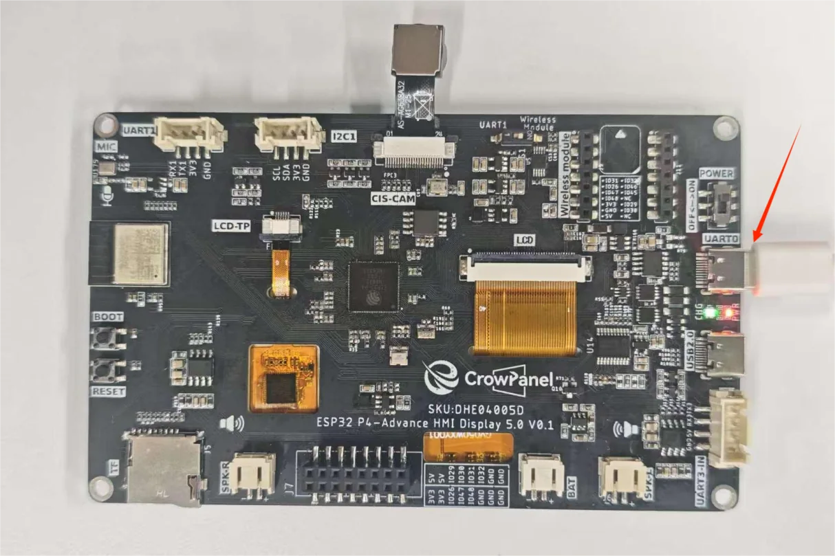
Use a USB Type-C data cable that supports data transfer to connect the ESP32-P4 development board to the computer. After connection, the power indicator on the development board should light up.
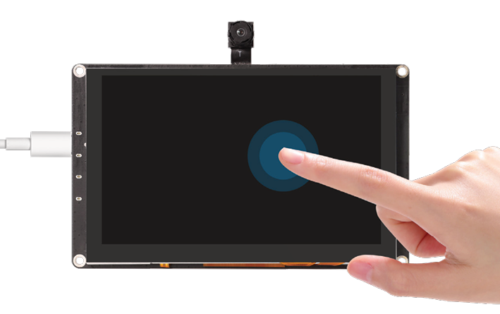
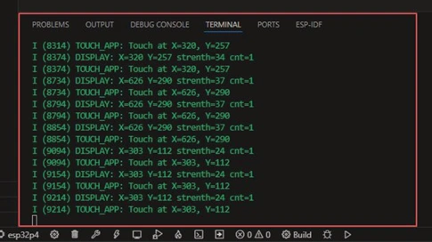
After waiting for a while, the code compilation and upload process was completed, and the monitor also opened. By touching the Advance-P4 screen, you will be able to see the coordinates of the screen you touched displayed.
6. Key Code Explanation
if (i2c_init() != ESP_OK) return;
if (touch_init() != ESP_OK) return;
xTaskCreate(touch_task, "touch_task", 4096, NULL, 5, &touch_task_handle);
app_main() initializes the custom I2C bus first, then initializes the GT911 touch controller. Either failure logs an error and stops startup. Only after both succeed is the 4096-byte touch-reading task created.
if (touch_read() == ESP_OK) {
    uint16_t x, y;
    bool pressed;
    get_coor(&x, &y, &pressed);
    if (pressed) ESP_LOGI(TAG, "Touch at X=%d, Y=%d", x, y);
}
The task reads one sample and obtains the current coordinates and press state through get_coor(). Coordinates are logged only while the panel is pressed, so release events do not print stale coordinate values.
The task polls every 50 ms, giving a sampling rate of about 20 Hz while limiting I2C traffic and serial log volume.
7. Observed Behavior
After the program is flashed and reset, the serial monitor outputs:
I (xxx) TOUCH_APP: Starting touch application
I (xxx) TOUCH_APP: Touch application started successfully
The task then enters polling. When the finger is not touching the screen, no coordinates are printed on the serial port; when the finger touches the screen, the serial port continuously prints.
The coordinates should change in real time as the finger moves, with the X range being 0–1023 and the Y range being 0–599. Printing stops after the finger is lifted. If the serial port never outputs coordinates, you should first check whether the I2C pins and the GT911 reset/interrupt pins are correct; if the coordinates do not change as the finger moves, you should check whether x_max/y_max are consistent with the panel.