5inch_P4_IDF_06_USB2_0_HID_Mouse: ESP32-P4 Touchscreen to USB HID Mouse
1. Course Introduction
This lesson uses the TinyUSB stack to emulate the ESP32-P4 as a USB HID mouse device, controlling the computer's mouse cursor movement through touchscreen swipe gestures. After the program is flashed, the development board connects to the computer via a separate USB cable and is recognized as a HID mouse; when the learner swipes a finger across the touchscreen, the mouse cursor on the computer moves accordingly, and the serial monitor prints the movement deltas synchronously.
Building on the Lesson 05 touchscreen lesson, this lesson introduces USB HID device development and serves as an entry point to USB peripheral applications. Through this experiment, learners will complete end-to-end validation of the full chain: I2C touch reading, USB enumeration, and HID report transmission.
2. Learning Objectives
- Be able to open the Lesson06 project in ESP-IDF and set the target chip to
esp32p4. - Be able to explain the roles of the HID report descriptor, configuration descriptor, and string descriptor in USB enumeration.
- Be able to explain the appropriate timing for calling
tud_hid_readyandtud_hid_mouse_report. - Be able to complete compilation and flashing, and confirm on the computer that the device is recognized as a mouse.
- Be able to control the computer cursor movement via touchscreen swiping, and observe the movement deltas printed on the serial monitor.
3. What You Will Need
- Applicable development board: CrowPanel Advanced 5-inch ESP32-P4 HMI AI Display Development Board.
- Software: VS Code, ESP-IDF Extension (ESP-IDF v5.5.4 or later).
- Project dependencies: retain the
main/main.c,peripheral/bsp_i2c,peripheral/bsp_display,peripheral/bsp_usbcomponents, along with theesp_lcd_touch_gt911andtinyusbmanaged components. - Configuration: target chip
esp32p4;
Code download link:
4. Software Operation Steps
This section follows the basic ESP-IDF workflow from Lesson 1. First, confirm that ESP-IDF v5.5.4, the UART flashing method, the actual serial port, and the target chip esp32p4 are all configured correctly, then check the project, components, configuration, and execution results item by item against the images below.
In File Explorer, locate this lesson's project directory, right-click and select "Open with VS Code";
Open the code for this lesson (Lesson 6); the image is for illustration only.

After opening, confirm that the project name in the window matches this lesson.
First select the code execution environment ESP-IDF v5.5.4, set the flashing method to UART, and then select the serial port actually corresponding to the development board. Next, in the ESP-IDF Extension panel, click Set Espressif Device Target and select esp32p4.
Once the configuration is complete, the status bar should display ESP-IDF v5.5.4, UART, the required COM port, and ESP32-P4.

Click SDK Configuration Editor in the VS Code bottom status bar or the ESP-IDF extension panel, and wait for the configuration page to finish loading completely before modifying any parameters. If the page is still loading, do not execute Build immediately.


In the search box, type flash, and ensure Flash SPI mode: QIO; Flash Sampling Mode: STR Mode; Flash SPI speed: 80 MHz; Flash size: 16 MB. These parameters should be consistent with the Advance-P4 onboard Flash.

Continue typing hid in the search box, and set TinyUSB HID interfaces count to 1, so that the USB device enumerates as a single HID mouse interface.
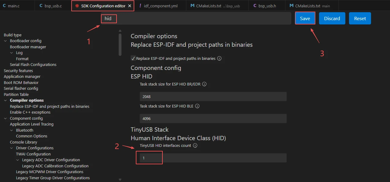
After verifying the configuration is correct, click Save in the top-right corner; confirm that the changes have been saved, then execute Build to compile.
Click Full Clean to clear the cache left over from the previous compilation. Perform this operation after the first compilation, after switching project configuration, or after modifying SDK parameters, to prevent stale configuration from affecting the new compilation result.

Then click Build.

Confirm that the development board is connected to the computer via USB, then click Select Port to Use and choose the corresponding serial port.
Click Flash to flash the firmware.

After flashing is complete, you can click Monitor to view the serial log and confirm whether the task was created normally. Press Ctrl + ] to exit the monitor.

In Device Manager (Windows) or system information, confirm that a new mouse device appears, with the product name Advance-P4 HID Mouse.

Finally, you can use the one-click operation button in the ESP-IDF status bar to sequentially perform compilation, flashing, and opening the serial monitor. Use this only after the project configuration, serial port, and code have all been verified correct; if you need to locate a problem, still follow the steps above one by one.

5. Hardware Operation Steps
Use a USB Type-C data cable that supports data transfer to connect the ESP32-P4 development board to the computer. After connecting, the board's power indicator should light up.
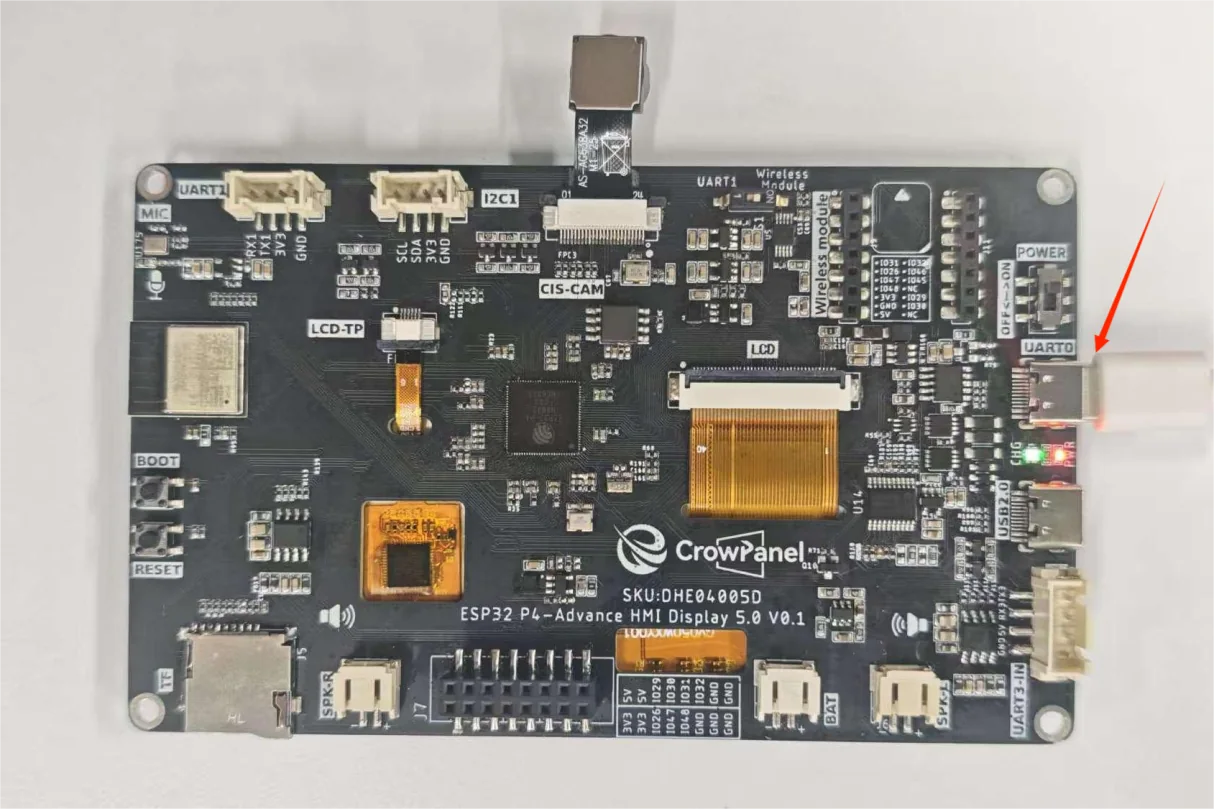
Then use another USB cable to connect the USB2.0 interface to the computer.
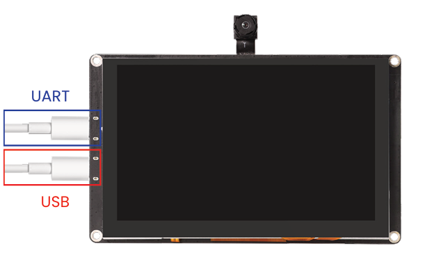
After flashing is complete and the board is reset, observe whether the computer shows a "new device connected" prompt, and a HID mouse should appear in Device Manager.
When you slide the screen of the Advance-P4, the mouse on your computer also moves along. At this moment, your Advance-P4 becomes your new mouse. Meanwhile, you can also see the corresponding coordinates printed on the monitor when you turn it on.


6. Key Code Explanation
if (i2c_init() != ESP_OK) return;
if (touch_init() != ESP_OK) return;
if (usb_init() != ESP_OK) return;
xTaskCreate(touch_mouse_task, "touch_mouse_task", 4096, NULL, 5,
            &touch_task_handle);
The application initializes I2C/touch input and then the USB HID BSP. The touch-to-mouse task is created only after all three subsystems succeed; a null task handle is treated as a startup error.
if (pressed && is_usb_ready()) {
    if (prev_pressed && prev_x != 0xffff && prev_y != 0xffff) {
        int16_t delta_x = (int16_t)x - (int16_t)prev_x;
        int16_t delta_y = (int16_t)y - (int16_t)prev_y;
        send_hid_mouse_delta(delta_x, delta_y);
    }
    prev_x = x;
    prev_y = y;
}
Absolute touch coordinates are converted to relative mouse movement by subtracting the previous sample. Reports are sent only after USB enumeration and after a valid previous point exists.
When the finger is released, the previous coordinates are reset to 0xffff. This prevents the next touch from producing a large jump from an old position. The task then waits 10 ms, giving approximately 100 Hz pointer updates.
7. Expected Results
After the program is flashed and reset, the serial monitor outputs:
I (xxx) TOUCH_MOUSE: Starting Touch Mouse application
I (xxx) USB_HID: Initializing USB HID Mouse
I (xxx) USB_HID: USB HID Mouse initialization completed
I (xxx) TOUCH_MOUSE: Touch Mouse application started successfully
I (xxx) TOUCH_MOUSE: Touch mouse task started
A new mouse device Advance-P4 HID Mouse appears in the computer's Device Manager. When a finger slides across the touchscreen, the computer cursor follows the movement, and the serial port prints the movement deltas synchronously.
After the finger lifts, printing stops and the cursor stops moving. If the device is not enumerated, first check whether the USB data cable supports data transfer and whether external_phy is set to false; if the cursor does not move, check the tud_hid_ready return value and whether the touch coordinates are normal.