5inch_P4_IDF_07_Turn_On_The_Screen: Lighting Up the RGB LCD Screen with ESP32-P4
1. Course Introduction
This course uses ESP-IDF to light up a 5-inch RGB LCD panel (800×480, RGB565) through an RGB LCD driver, and uses LVGL to display the text "Hello Elecrow" in the center of the screen. After the program is burned in, the development board is powered on and reset; when the RGB LCD bus and the panel are initialized, the backlight is turned on at maximum brightness, the screen shows a white background, and the welcome text is presented in a black 42-point font. This course is the foundation of the display teaching system, and it introduces the RGB LCD high-speed bus and the LVGL graphics library for the first time. Through this experiment, learners will complete the verification of the complete display link covering power management, LCD panel initialization, LVGL rendering, and backlight control.
2. Learning Objectives
- Be able to open the Lesson07 project in ESP-IDF and set the target chip to
esp32p4. - Be able to explain the role of the bsp_stc8h1kxx.c component, which controls the screen backlight.
- Be able to explain the relationship among the RGB LCD bus, DBI I/O, and DPI panel configuration.
- Be able to complete compilation and flashing, and observe whether the screen displays the text "Hello Elecrow".
- Be able to determine whether the power, DPI, and LVGL stages are functioning properly based on whether the screen lights up and the text is displayed.
3. Prerequisites
- Target development board: CrowPanel Advanced 5-inch ESP32-P4 HMI AI Display Development Board.
- Software: VS Code, ESP-IDF Extension (ESP-IDF v5.5.4 or later).
- Project dependencies: keep the
main/main.cfile, theperipheral/bsp_illuminatecomponent, and theesp_lvgl_portandlvglmanaged components. - Configuration: target chip
esp32p4.
Code download link:
4. Software Operation Steps
The operations in this section follow the basic ESP-IDF workflow introduced in Lesson 1. Please first confirm that ESP-IDF v5.5.4, the UART flashing method, the actual serial port, and the target chip esp32p4 are set correctly, then follow the images below to check the project, components, configuration, and running results step by step.
In File Explorer, locate this lesson's project directory, right-click and select to open it with VS Code;
You need to open this lesson's code (Lesson 7); the image is for illustration only.
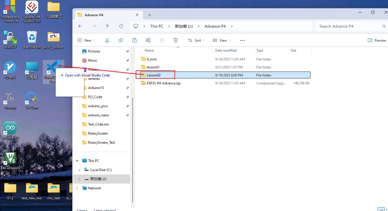
After opening, confirm that the project name in the window matches this lesson.
First select the code runtime environment ESP-IDF v5.5.4, set the flashing method to UART, and then select the serial port that actually corresponds to the development board. Next, in the ESP-IDF Extension panel, click Set Espressif Device Target and select esp32p4.
After the settings are complete, the status bar should display ESP-IDF v5.5.4, UART, the required COM port, and ESP32-P4.

Click SDK Configuration Editor in the VS Code status bar at the bottom or in the ESP-IDF extension panel, and wait for the configuration page to fully load before modifying parameters. If the page is still loading, do not run Build immediately.

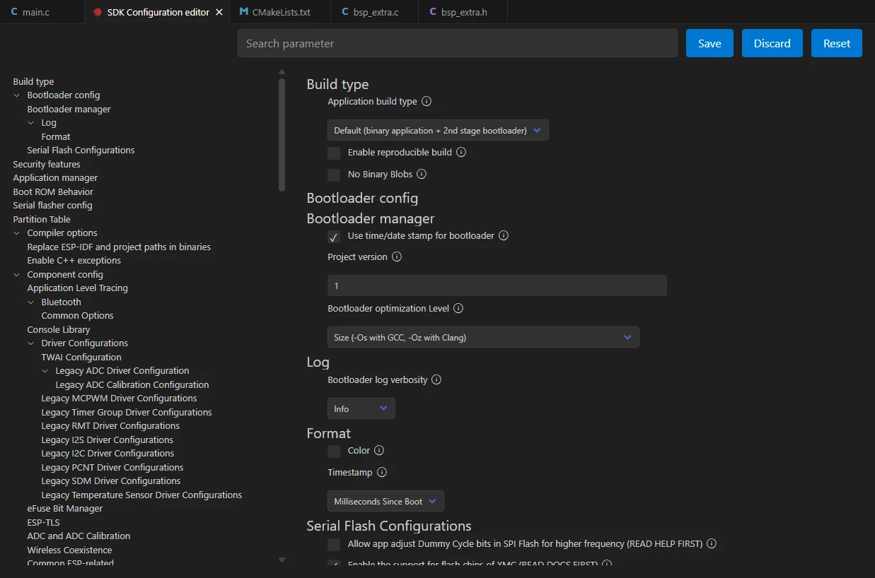
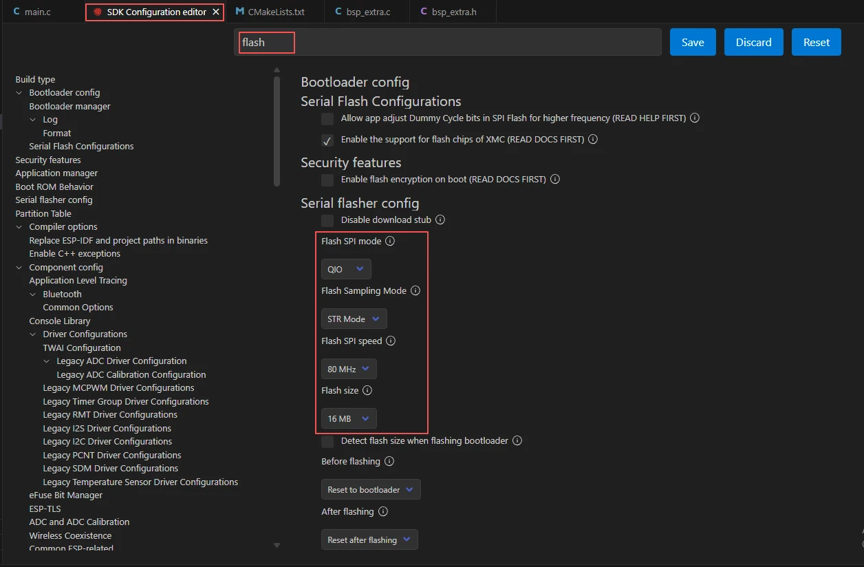
In the search box, type flash and ensure Flash SPI mode: QIO; Flash Sampling Mode: STR Mode; Flash SPI speed: 80 MHz; Flash size: 16 MB. These parameters should be consistent with the on-board Flash of the Advance-P4.
In the SDK Configuration Editor search box, type CONFIG_IDF_EXPERIMENTAL_FEATURES and check this option to enable experimental features.

After enabling experimental features, search for PSRAM, enable PSRAM in the order shown in the image, and set its operating frequency to 200 MHz to provide sufficient memory for the screen frame buffer.

Next, search for font and enable the LVGL Montserrat 42-point font used in the code; otherwise, the corresponding font will not be found at compile time, or the text will not display properly after running.

Finally, import the custom partition table provided by the project to reasonably allocate the storage space of each partition in Flash, ensuring that resources such as images, fonts, and local files can be read and written normally.

After checking that the configuration is correct, click Save in the upper-right corner; confirm that the changes have been saved, then run Build to compile.
Click Full Clean to clear the cache left over from the previous compilation. Perform this operation after the first compile, after switching project configuration, or after modifying SDK parameters to avoid old configurations affecting new compilation results.

Then click Build.

Confirm that the development board is connected to the computer via USB, then click Select Port to Use to choose the corresponding serial port.
Click Flash to flash the firmware.

After flashing completes, you can click Monitor to view the serial log and confirm whether tasks are created normally. Press Ctrl + ] to exit the monitor.

After flashing completes, wait for the device to reset and observe whether the screen lights up and displays text.

Finally, you can use the one-click operation button in the ESP-IDF status bar to continuously execute compilation, flashing, and opening the serial monitor. Use this only after the project configuration, serial port, and code have all been confirmed correct; if you need to locate a problem, still follow the steps above and execute them one by one.

5. Hardware Operation Steps
Use a USB Type-C data cable that supports data transfer to connect the ESP32-P4 development board to the computer. After connecting, the board's power indicator should light up.

After flashing completes and the board resets, observe whether the screen backlight lights up. If the backlight does not light up, first check the backlight PWM configuration.
Observe whether the screen displays a white background with the centered black text "Hello Elecrow"; the text should be clear, without artifacts or misalignment.
As shown in the figure, an additional power cable can be used to supply power to the Advance-P4 to ensure stable screen display.
6. Key Code Explanation
system_init() initializes the I2C bus and STC8 board controller before starting the display and LVGL. The backlight is set to 100% only after display_init() succeeds. Any error enters init_fail_handler(), which repeatedly identifies the failed module in the serial log.
if (lvgl_port_lock(0) != true) {
    MAIN_ERROR("LVGL lock failed");
    return;
}
lv_obj_t *screen = lv_screen_active();
lvgl_show_hello_elecrow() acquires the LVGL lock before accessing the active screen. If the non-blocking lock attempt fails, it logs the error and exits without modifying LVGL objects.
lv_obj_t *hello_label = lv_label_create(screen);
lv_label_set_text(hello_label, "Hello Elecrow");
lv_style_set_text_font(&label_style, &lv_font_montserrat_42);
lv_obj_center(hello_label);
lvgl_port_unlock();
The function sets a white screen background, creates the label, applies a black Montserrat 42 font style, centers the object, and then releases the LVGL lock so the display task can render it.
7. Experimental Results
After the program is flashed and the device resets, the serial monitor outputs:
I (xxx) MAIN: Start Hello Elecrow Display Demo
I (xxx) ILLUMINATE: ...
I (xxx) MAIN: LCD init success
I (xxx) MAIN: LCD backlight opened (brightness: 100)
I (xxx) MAIN: Show 'Hello Elecrow' success
Screen behavior: the backlight turns on to maximum brightness, displaying a white background with the black text "Hello Elecrow" (Montserrat 42-point font) at the center of the screen; the text is clear, centered, and free of artifacts. The image should remain stable, with no flickering, tearing, or partial missing content. If the backlight is on but no text appears, check whether the LVGL font is enabled and whether lvgl_port_lock succeeded; if the screen remains completely off, prioritize checking backlight PWM.