5inch_P4_IDF_09_LVGL_Lighting_Control: ESP32-P4 LVGL Touch-Controlled LED
1. Course Introduction
This lesson builds an LVGL LED control interface on a 5-inch screen. The source code first initializes I2C, STC8H1KXX, touch, LCD, backlight, and GPIO48, then creates a white background, a title, and two buttons, LED ON and LED OFF. The button click events respectively call gpio_extra_set_level(true/false) to control the on-board LED.
2. Learning Objectives
- Understand the creation workflow of LVGL screens, labels, buttons, and click event callbacks.
- Master the reason for using
lvgl_port_lock()/lvgl_port_unlock()before and after LVGL operations. - Be able to connect UI events to the high/low level control of GPIO48.
- Understand the sequential relationship among LCD, touch, and backlight initialization.
3. Preparation
- Applicable development board: CrowPanel Advanced 5-inch ESP32-P4 HMI AI Display Development Board.
- Software: VS Code, ESP-IDF Extension (ESP-IDF v5.5.4 and above).
- Project dependencies: retain the
main/main.c,peripheral/bsp_illuminate,peripheral/bsp_display,peripheral/bsp_i2c,peripheral/bsp_extracomponents, as well as theesp_lcd_touch_gt911,esp_lvgl_port,lvglmanaged components. - Configuration: target chip
esp32p4.
Code download link:
4. Software Operation Steps
In VS Code, open the ESP-IDF Extension panel, click Open ESP-IDF Project, and select the Lesson09-LVGL_Lighting_Control folder.
You can also drag this project folder directly into VS Code.

First select the code running environment ESP-IDF v5.5.4, set the flashing method to UART, then select the serial port that corresponds to the actual development board. Next, in the ESP-IDF Extension panel, click Set Espressif Device Target and select esp32p4. After the settings are complete, the status bar should display ESP-IDF v5.5.4, UART, the required COM port, and ESP32-P4.

Click SDK Configuration Editor in the bottom status bar of VS Code or in the ESP-IDF extension panel, and wait for the configuration page to fully load before modifying any parameters. If the page is still loading, do not execute Build immediately.


In the search box, enter flash, and ensure Flash SPI mode: QIO; Flash Sampling Mode: STR Mode; Flash SPI speed: 80 MHz; Flash size: 16 MB. These parameters should be consistent with the Advance-P4 on-board Flash.

Next, refer to the "4. Software Operation Steps" in
Lesson07_Turn_on_the_Screento complete the detailed SDK configuration; the relevant configuration methods have already been explained in Lesson 7.Note: The LVGL font size used in this lesson is 24 points; please modify it accordingly.
After verifying that the configuration is correct, click Save in the upper-right corner; confirm that the changes have been saved, then execute Build to compile.
Click Full Clean to clear the cache left by the previous compilation. Performing this operation after the first compilation, after switching project configuration, or after modifying SDK parameters can prevent old configurations from affecting the new compilation results.

Click Build to compile the project.

Confirm that the development board is connected to the computer via USB, click Select Port to Use to select the serial port, then click Flash to flash the firmware.

After flashing is complete, click Monitor to open the serial monitor; you should see the UI created successfully log. Press Ctrl + ] to exit the monitor.

After flashing is complete, wait for the device to reset, and observe whether the screen lights up and displays the LED control interface.
Finally, you can use the one-click operation buttons in the ESP-IDF status bar to sequentially execute compilation, flashing, and opening the serial monitor. Use this only after the project configuration, serial port, and code have all been confirmed correct; if you need to locate a problem, you should still follow the steps above one by one.

5. Hardware Operation Steps
Use a USB data cable to connect the ESP32-P4 development board to the computer. Confirm that the LCD and touch screen flexible cables are properly connected.

If you want to control the LED, you need to switch this switch to the left side of UART1
Then, switch the toggle switch on the 5-inch Advance-P4 to the UART1 position. Only in this way can the UART1 interface be used.

This is the design on the hardware side.

Switch to UART1 port:
Among the three interfaces shown in the figure, only the UART1 interface can be used at this time.
Alternatively, the expansion header at the bottom can also be used.
That is, either the UART1 interface or the expansion header can be used, but not both.
Switch to Wireless Module port:
Among the three interfaces shown in the figure, only the wireless module can be used at this time.
Alternatively, the expansion header at the bottom can also be used.
That is, either the wireless module or the expansion header can be used, but not both.
Summary:
The UART1 interface and the Wireless Module can only be used when switched to the corresponding port.
The expansion header at the bottom can be used regardless of the position of the mode switch, but it cannot be used simultaneously with the above interfaces. (When used simultaneously, only one of the three interfaces can be selected.)
Connect the LED

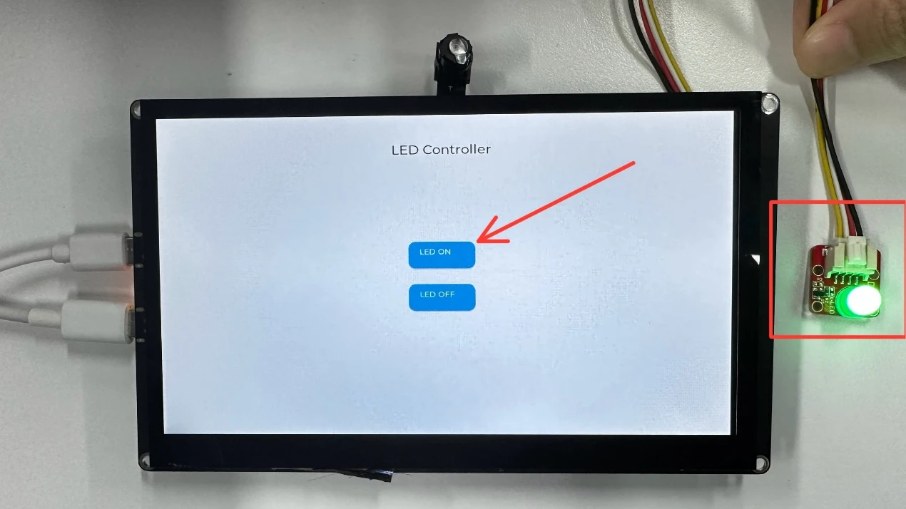
After flashing is complete and the device resets, observe whether the screen displays a white background, the title "LED Controller", and two buttons, with the layout centered and free of misalignment.

Tap the "LED ON" button on the screen with your finger, and observe whether the on-board LED lights up and whether the serial port prints LED turned ON.

Click the "LED OFF" button, and observe whether the LED turns off and whether the serial port prints LED turned OFF, confirming that the touch interaction works correctly.

6. Key Code Explanation
The LVGL click event callback receives an event object, but this example does not need to read any event details, so e is explicitly cast to unused. The ON and OFF callbacks respectively output logs and set the GPIO48 level.
lv_obj_t *btn_on = lv_btn_create(scr);
lv_obj_set_size(btn_on, 120, 50);
lv_obj_align(btn_on, LV_ALIGN_CENTER, 0, -40);
lv_obj_add_event_cb(btn_on, btn_on_click_event, LV_EVENT_CLICKED, NULL);
After each button is created, its size, position, and LV_EVENT_CLICKED callback are set. The child labels display LED ON and LED OFF, while the callbacks drive the BSP output and write the result to the log.
err = display_init();
err = set_lcd_blight(100);
err = gpio_extra_init();
gpio_extra_set_level(false);
system_init() now performs the complete chain: i2c_init(), stc8_i2c_init(), touch_init(), display_init(), full backlight, and LED GPIO. The LED is forced off before create_led_control_ui() builds the interface. Any failed step enters the common error loop instead of continuing with partially initialized hardware.
7. Experimental Observations
After startup, the screen displays a white background, the LED Controller title, and two buttons. When LED ON is clicked, the LED corresponding to GPIO48 lights up and outputs LED turned ON; when LED OFF is clicked, the LED turns off and outputs the corresponding log. If touch initialization or display initialization fails, the serial port will continuously report the failed module.