5inch_P4_IDF_10_Temperature_Humidity: ESP32-P4 Temperature and Humidity Sensor DHT20
1. Course Introduction
This lesson uses the DHT20 sensor to periodically read temperature and humidity and display the results in the center of the LVGL screen. Init() sequentially initializes I2C, STC8, DHT20, LCD, and the 100% backlight; dht20_display() creates a label; dht20_read_task checks the calibration status, reads the measured values, and updates the label every second.
2. Learning Objectives
- Understand the DHT20 calibration check, reinitialization, and data reading flow.
- Be able to use
dht20_data_tto obtaintemperatureandhumidity. - Master the method of updating UI text within the LVGL thread-safe lock.
- Be able to identify the on-screen prompts and serial error logs when sensor reading fails.
3. Prerequisites
- Applicable development board: CrowPanel Advanced 5-inch ESP32-P4 HMI AI Display Development Board.
- Software: VS Code, ESP-IDF Extension (ESP-IDF v5.5.4 or later).
- Project dependencies: Keep the
main/main.c,peripheral/bsp_dht20,peripheral/bsp_i2c,peripheral/bsp_illuminatecomponents, as well as theesp_lvgl_portandlvglmanaged components.
Code download link:
4. Software Operation Steps
Open the ESP-IDF Extension panel in VS Code, click Open ESP-IDF Project, and select the Lesson10-Temperature_and_Humidity folder.
You can also drag this project folder directly into VS Code.

First, select the code runtime environment ESP-IDF v5.5.4, set the flashing method to UART, and then select the serial port corresponding to the actual development board. Next, click Set Espressif Device Target in the ESP-IDF Extension panel and select esp32p4. After the setup is complete, the status bar should display ESP-IDF v5.5.4, UART, the required COM port, and ESP32-P4.

Click SDK Configuration Editor in the VS Code bottom status bar or the ESP-IDF extension panel, and wait until the configuration page is fully loaded before modifying parameters. If the page is still loading, do not execute Build immediately.


Enter flash in the search box and ensure Flash SPI mode: QIO; Flash Sampling Mode: STR Mode; Flash SPI speed: 80 MHz; Flash size: 16 MB. These parameters should match the onboard Flash of the Advance-P4.

Next, refer to "4. Software Operation Steps" in
Lesson07_Turn_on_the_Screento complete the detailed SDK configuration; the related configuration methods have been explained in Lesson 7.Note: The LVGL font size used in this lesson is 30; please modify it accordingly.
After checking that the configuration is correct, click Save in the upper-right corner; confirm that the changes have been saved, then execute Build to compile.
Click Full Clean to clear the cache left over from the previous compilation. Perform this operation after the first compilation, switching project configurations, or modifying SDK parameters, to avoid old configurations affecting new compilation results.

Click Build to compile the project.

Confirm that the development board is connected to the computer via USB, click Select Port to Use to choose the serial port, and click Flash to flash the firmware.

After flashing is complete, click Monitor to open the serial monitor; you should see is calibrated.... and the temperature and humidity value logs. Press Ctrl + ] to exit the monitor.

After flashing is complete, wait for the device to reset and observe whether the screen displays the temperature and humidity values.

Finally, you can use the one-click operation button in the ESP-IDF status bar to sequentially execute compilation, flashing, and opening the serial monitor. Use this only after the project configuration, serial port, and code are all confirmed to be correct; if you need to locate a problem, still follow the steps above one by one.

5. Hardware Operation Steps
Connect the ESP32-P4 development board to the computer using a USB cable. Confirm that the DHT20 sensor and the LCD ribbon cable are properly connected.
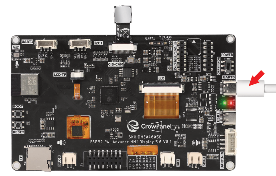
Connect the DHT20 temperature and humidity sensor

After flashing is complete and the device resets, observe whether the screen displays a black background with white temperature and humidity text.
Observe whether the temperature and humidity values on the screen refresh every second; the values should be within the room temperature range (e.g., temperature 25.5°C, humidity 30.0%).

You can gently cover the DHT20 sensor with your finger (avoid using sharp objects) and observe whether the temperature rises and the humidity changes, to verify the sensor's response.
6. Key Code Explanation
err = i2c_init();
err = stc8_i2c_init();
err = dht20_begin();
err = display_init();
err = set_lcd_blight(100);
Init() prepares the shared I2C bus and STC8 board controller before starting the DHT20, display/LVGL, and backlight. Every return value is checked; a failed module enters init_fail() and prevents later hardware from running in an invalid state.
if (dht20_is_calibrated() != ESP_OK) {
    if (dht20_begin() != ESP_OK) continue;
}
if (dht20_read_data(&measurements) != ESP_OK) {
    lv_label_set_text(dht20_data, "dht20 read data error");
}
Each task cycle verifies calibration and reinitializes the sensor when necessary. A failed measurement updates both the screen and serial log; valid temperature and humidity values continue to the display update path.
snprintf(buffer, sizeof(buffer),
         "Temperature = %.1f C  Humidity = %.1f %%",
         temperature, humidity);
lv_label_set_text(dht20_data, buffer);
The fixed 60-byte buffer formats both values to one decimal place. dht20_read_task acquires the LVGL lock before calling update_dht20_value() and releases it afterward, keeping the UI update thread-safe.
app_main() first creates the initial black-screen label, then starts the 4096-byte sensor task at configMAX_PRIORITIES - 5. Its one-second loop delay refreshes the measurement approximately once per second.
7. Experimental Observations
The screen displays Temperature = ... C Humidity = ... % on a black background, with the values changing approximately once per second; the serial port outputs the temperature and humidity synchronously. When the sensor is not connected or the read fails, the screen displays dht20 read data error and the serial port outputs an error message.