5inch_P4_IDF_11_Playback_After_Recording: ESP32-P4 Record and Playback
1. Course Introduction
This lesson demonstrates "record and immediately play back": the program initializes I2C, STC8, audio control, the power amplifier, the I2S audio link, and the microphone, then calls mic_read_to_audio(5) to record for 5 seconds and play back the raw audio. After playback completes, the main task stays alive, waiting once per second.
2. Learning Objectives
- Understand the dependencies among the audio amplifier, the I2S playback chain, and microphone initialization.
- Be able to use
mic_read_to_audio(5)to complete 5-second recording and playback. - Understand how
init_or_halt()uniformly handles errors. - Be able to determine from serial logs whether recording and playback have completed.
3. Preparation
- Compatible development board: CrowPanel Advanced 5-inch ESP32-P4 HMI AI Display Development Board.
- Software: VS Code, ESP-IDF Extension (ESP-IDF v5.5.4 or later).
- Project dependencies: keep the
main/main.c,peripheral/bsp_mic, andperipheral/bsp_audiocomponents.
Code download link:
4. Software Operation Steps
Open the ESP-IDF Extension panel in VS Code, click Open ESP-IDF Project, and select the Lesson11-Playback_After_Recording folder.
You can also drag the project folder directly into VS Code.

First select the code execution environment ESP-IDF v5.5.4, set the flashing method to UART, and then select the serial port that actually corresponds to the development board. Next, in the ESP-IDF Extension panel, click Set Espressif Device Target and select esp32p4. After the setup is complete, the status bar should display ESP-IDF v5.5.4, UART, the required COM port, and ESP32-P4.

Click SDK Configuration Editor in the VS Code bottom status bar or the ESP-IDF extension panel, and wait until the configuration page is fully loaded before modifying parameters. If the page is still loading, do not run Build immediately.


Enter flash in the search box and ensure Flash SPI mode: QIO; Flash Sampling Mode: STR Mode; Flash SPI speed: 80 MHz; Flash size: 16 MB. These parameters should match the on-board Flash of the Advance-P4.

Next, refer to "4. Software Operation Steps" in
Lesson07_Turn_on_the_Screento complete the detailed SDK configuration; the related configuration methods were explained in Lesson 7.
After verifying that the configuration is correct, click Save in the upper-right corner; confirm that the changes have been saved, then run Build to compile.
Click Full Clean to clear the cache left over from the previous compilation. Perform this operation after the first compilation, when switching project configurations, or after modifying SDK parameters, to prevent old configurations from affecting the new build result.

Click Build to compile the project.

Confirm that the development board is connected to the computer via USB, click Select Port to Use to choose the serial port, and then click Flash to flash the firmware.

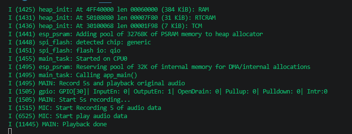
After flashing is complete, click Monitor to open the serial monitor; you should see recording and playback logs. Press Ctrl + ] to exit the monitor.
After flashing, the program automatically starts recording; speak into the microphone for 5 seconds and wait for playback.
To hear audio playback, a speaker must be connected.

Finally, you can use the one-click operation button in the ESP-IDF status bar to sequentially perform compilation, flashing, and opening the serial monitor. Use this only after the project configuration, serial port, and code have all been verified; if you need to troubleshoot, still follow the steps above one by one.

5. Hardware Operation Steps
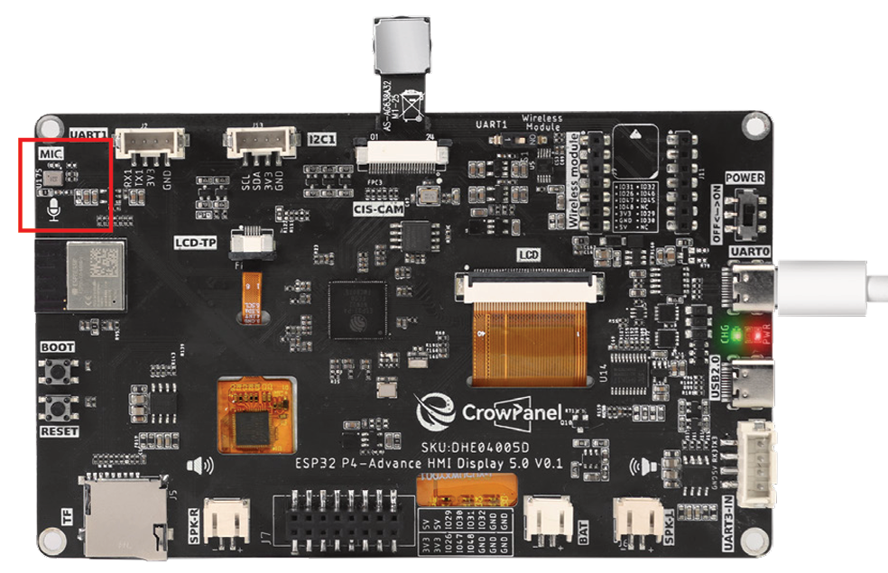
Connect the ESP32-P4 development board to the computer using a USB data cable. Confirm that the speaker and microphone are correctly wired.

After flashing is complete and the board is reset, observe whether the serial port prints Start 5s recording...; speak into the microphone at this point.
After 5 seconds of recording, observe whether the serial port prints Start play audio data; the speaker should play the sound that was just recorded.
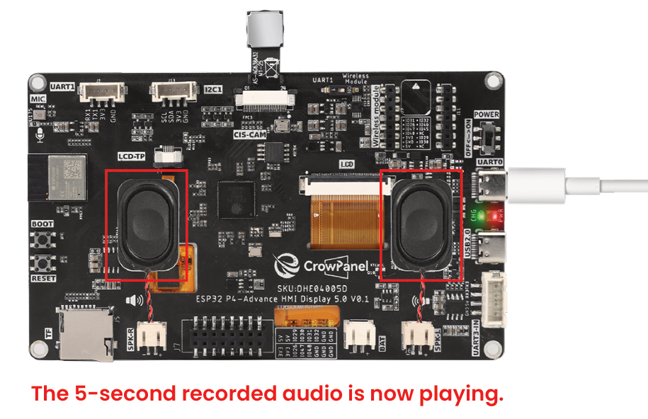
After playback ends, observe whether the serial port prints Playback done to confirm that the entire process is complete.
6. Key Code Explanation
err = i2c_init();
err = stc8_i2c_init();
err = audio_ctrl_init();
set_Audio_ctrl(false);
err = audio_init();
err = mic_init();
The new startup sequence initializes I2C and the STC8 board controller before the audio chain. It then initializes amplifier control, keeps the amplifier disabled during setup, starts the audio output and microphone, and halts through init_or_halt() if any step fails.
MAIN_INFO("Start 5s recording...");
err = mic_read_to_audio(5);
if (err != ESP_OK)
    MAIN_ERROR("record/playback error: %s", esp_err_to_name(err));
else
    MAIN_INFO("Playback done");
mic_read_to_audio(5) records five seconds from the microphone and plays the captured audio through the initialized output path. The return code selects the failure or completion log. After this one recording/playback cycle, app_main() remains alive with a one-second delay loop.
7. Experimental Observations
After the serial port outputs Start 5s recording..., the development board captures sound for about 5 seconds, then plays back the recording through the speaker and outputs Playback done. If microphone, amplifier, or I2S initialization fails, the serial port displays the corresponding module error and stops subsequent processes.