5inch_P4_IDF_16_WiFi_Weather: ESP32-P4 Retrieving Weather Data over WiFi
1. Course Introduction
This lesson combines Wi-Fi, weather requests, and the LVGL graphical interface. After initializing I2C, STC8, and the LCD, the program turns off the backlight, starts the Wi-Fi STA, creates a weather object, and requests weather data. Once the results are obtained, it overlays the temperature, weather description, date, and day of the week onto the ui_home background image, and finally sets the backlight to 100.
2. Learning Objectives
- Understand the dependency between the Wi-Fi connection status and weather requests.
- Be able to explain the purpose of the data returned by
weather_create()andweather_get_weather(). - Master how to set the background image, label position, font, and color on LVGL objects.
- Be able to locate issues based on connection failures, weather request failures, and UI display results.
3. Prerequisites
- Compatible development board: CrowPanel Advanced 5-inch ESP32-P4 HMI AI Display Development Board.
- Software: VS Code, ESP-IDF Extension (ESP-IDF v5.5.4 or later).
- Project dependencies: Keep the
main/main.c,components/bsp_wifi,components/app_weather,components/bsp_display, andcomponents/bsp_i2ccomponents, as well as thelvgl,esp_lvgl_port, andesp_lcd_touch_gt911managed components. - Network: A working 2.4 GHz WiFi router; the SSID and password must be configured in the
bsp_wifi_connectcall withinmain.c. - Resources:
main/ui/image_both.ccontains the full-screen background image data and must be preserved.
Code download link:
4. Software Operation Steps
Open the ESP-IDF Extension panel in VS Code, click Open ESP-IDF Project, and select the Lesson16_Get_weather_via_WiFi folder.

First, select the code execution environment ESP-IDF v5.5.4, set the flashing method to UART, and then select the serial port that corresponds to your actual development board. Next, click Set Espressif Device Target in the ESP-IDF Extension panel and select esp32p4. After the configuration is complete, the status bar should display ESP-IDF v5.5.4, UART, the required COM port, and ESP32-P4.

Open main/main.c and change the SSID and password in bsp_wifi_connect("yanfa_software", "yanfa-123456") to match your router information, then save.

Click SDK Configuration Editor and wait for the configuration page to fully load.


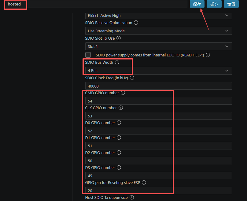
Enter hosted in the search box and set the SDIO parameters for the onboard ESP32-C6 as follows: Bus Width 4 Bits, Clock 40000 kHz, CMD GPIO 54, CLK GPIO 53, D0/D1/D2/D3 GPIO 52, 51, 50, and 49 respectively, and Reset GPIO 20.
Enter flash in the search box and ensure Flash SPI mode: QIO; Flash Sampling Mode: STR Mode; Flash SPI speed: 80 MHz; Flash size: 16 MB.

Next, refer to "4. Software Operation Steps" in
Lesson07_Turn_on_the_Screento complete the detailed SDK configuration; the related configuration methods were explained in Lesson 7.Note: The LVGL font sizes used in this lesson are 30 and 48; please modify them accordingly.
After verifying that the configuration is correct, click Save in the upper-right corner; confirm that the changes have been saved, then run Build to compile.
Click Full Clean to clear the cache left by the previous compilation. Perform this operation after the first compilation, when switching project configurations, or after modifying SDK parameters, to prevent old configurations from affecting the new compilation results.
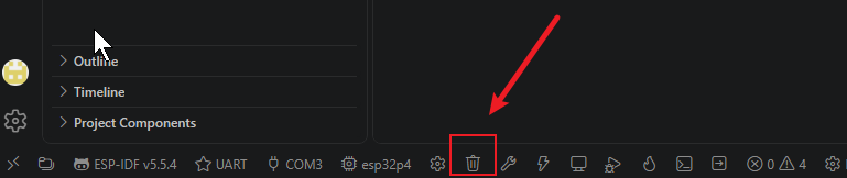
Click Build to compile the project.

Confirm that the development board is connected to the computer via USB, click Select Port to Use to select the serial port, then click Flash to flash the firmware.
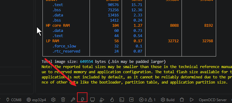
After flashing is complete, click Monitor to open the serial monitor; you should see WiFi connection and weather retrieval logs. Press Ctrl + ] to exit the monitor.

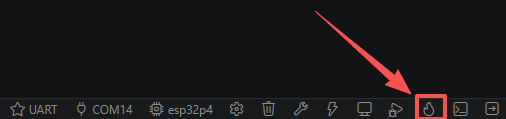
Finally, you can use the one-click operation button in the ESP-IDF status bar to sequentially execute compilation, flashing, and opening the serial monitor. Use this only after the project configuration, serial port, and code have all been confirmed correct; if you need to troubleshoot issues, still follow the steps above one by one.
5. Hardware Operation Steps
Connect the ESP32-P4 development board to the computer using a USB cable. Confirm that the WiFi antenna (if required) and the LCD ribbon cable are connected.

The ESP32-C6 module is already mounted on the board.

After flashing is complete and the board is reset, observe whether the serial port prints WiFi connected with IP:... to confirm a successful network connection.
Observe whether the serial port prints weather data (temperature, weather description, timestamp) to confirm that the HTTP request succeeded.
Observe whether the screen displays the background image overlaid with temperature, weather, date, and day-of-week text, with the backlight lit.

6. Key Code Explanation
err = i2c_init();
err = stc8_i2c_init();
err = display_init();
err = set_lcd_blight(0);
bsp_wifi_init();
bsp_wifi_sta_init();
bsp_wifi_connect("yanfa_software", "yanfa-123456");
weather_t *weather_handle = weather_create();
if (WIFI_CONNECTED == bsp_wifi_get_state()) {
weather_get_weather(weather_handle, &temp_c, weather_text, ×tamp);
}
The current application initializes I2C, STC8, and the display, then deliberately keeps the backlight at 0 while data and UI objects are prepared. It starts Wi-Fi STA mode, connects with the configured credentials, creates the weather client, and calls the service only after the BSP reports WIFI_CONNECTED.
tv.tv_sec = timestamp;
settimeofday(&tv, NULL);
strftime(date_str, sizeof(date_str), "%Y/%m/%d", local_time);
strftime(week_str, sizeof(week_str), "%A", local_time);
The timestamp returned by the weather service is installed as system time. localtime() and strftime() then produce the date and weekday strings used by the interface.
lv_image_set_src(ui_home, &image_both);
lv_obj_set_size(ui_home, lv_pct(100), lv_pct(100));
lv_label_set_text(temperature_label_, temp_text);
lv_label_set_text(weather_label_, weather_text);
Inside the LVGL lock, ui_home stretches image_both over the full 800×480 screen and receives four right-aligned labels for temperature, weather, date, and weekday. After unlocking, the code waits one second for LVGL to flush the completed frame and only then raises the backlight to 100%, avoiding an incomplete startup screen.
7. Observed Behavior
When the network connection and weather request both succeed, the screen displays the background image, current temperature, weather description, date, and day of the week, with the backlight lit. If Wi-Fi is not connected or the request fails, the program cannot obtain valid weather text, and you must troubleshoot based on the Wi-Fi status and serial logs.