5inch_P4_IDF_17_WiFi_Functions: ESP32-P4 WiFi Three Operating Modes
1. Course Introduction
This lesson contains three Wi-Fi projects: the station project connects to a specified router, the softAP project creates an ELECROW hotspot, and the softAP+station project simultaneously connects to the upstream Wi-Fi and provides a hotspot. All three entry points use ESP-IDF event callbacks and the FreeRTOS event group to synchronize connection success or failure status.
2. Learning Objectives
- Understand the differences among the STA, SoftAP, and APSTA operating modes.
- Be able to explain the initialization sequence of NVS, the network interface, the event loop, and the Wi-Fi driver.
- Master the use of
WIFI_CONNECTED_BIT/WIFI_FAIL_BITto wait for asynchronous connection results. - Be able to determine network status based on SSID, IP address, retry, and client-join logs.
3. Prerequisites
- Applicable development board: CrowPanel Advanced 5-inch ESP32-P4 HMI AI Display Development Board.
- Software: VS Code, ESP-IDF Extension (ESP-IDF v5.5.4 or later).
- Project dependencies: The three projects are
ESP32_P4-station,ESP32_P4-softAP, andESP32_P4-softap_sta, all of which depend on system components such asesp_wifiandnvs_flash. - Network: A working 2.4 GHz WiFi router (required for STA and AP+STA modes); the SSID and password must be configured in the source code macro definitions.
Code download link:
4. Software Operation Steps
In VS Code, open the ESP-IDF Extension panel, click Open ESP-IDF Project, and select the ESP32_P4-station folder (Station mode).

First, select the code execution environment ESP-IDF v5.5.4, set the flashing method to UART, and then select the serial port that actually corresponds to the development board. Next, in the ESP-IDF Extension panel, click Set Espressif Device Target and select esp32p4. After the configuration is complete, the status bar should display ESP-IDF v5.5.4, UART, the required COM port, and ESP32-P4.

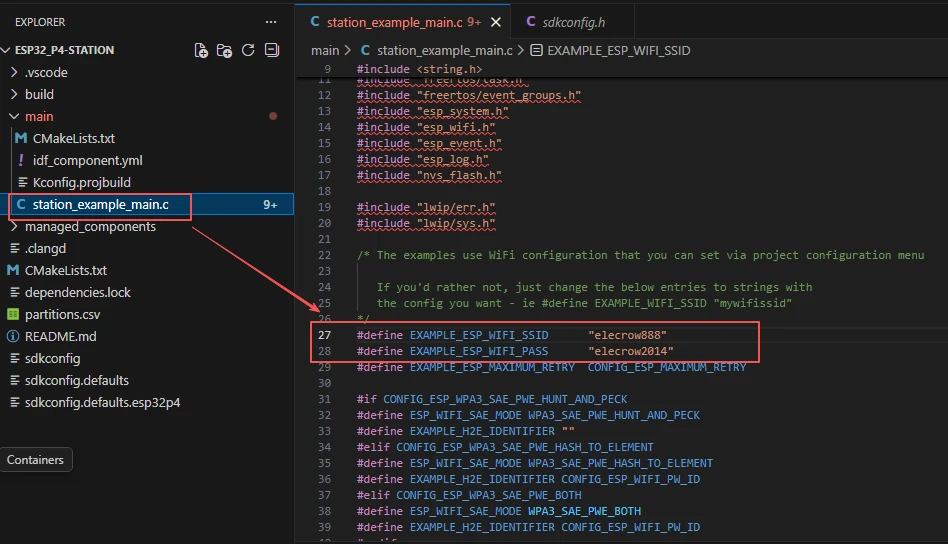
To modify the Station network information, edit EXAMPLE_ESP_WIFI_SSID and EXAMPLE_ESP_WIFI_PASS in main/station_example_main.c.
In the Station, softAP, and softap_sta projects, respectively open the SDK Configuration Editor and wait for the configuration page to fully load.


In the search box, type hosted and set the SDIO parameters of the onboard ESP32-C6 as follows: Bus Width 4 Bits, Clock 40000 kHz, CMD GPIO 54, CLK GPIO 53, D0/D1/D2/D3 GPIO 52, 51, 50, and 49 respectively, and Reset GPIO 20.
All three projects should verify this configuration.

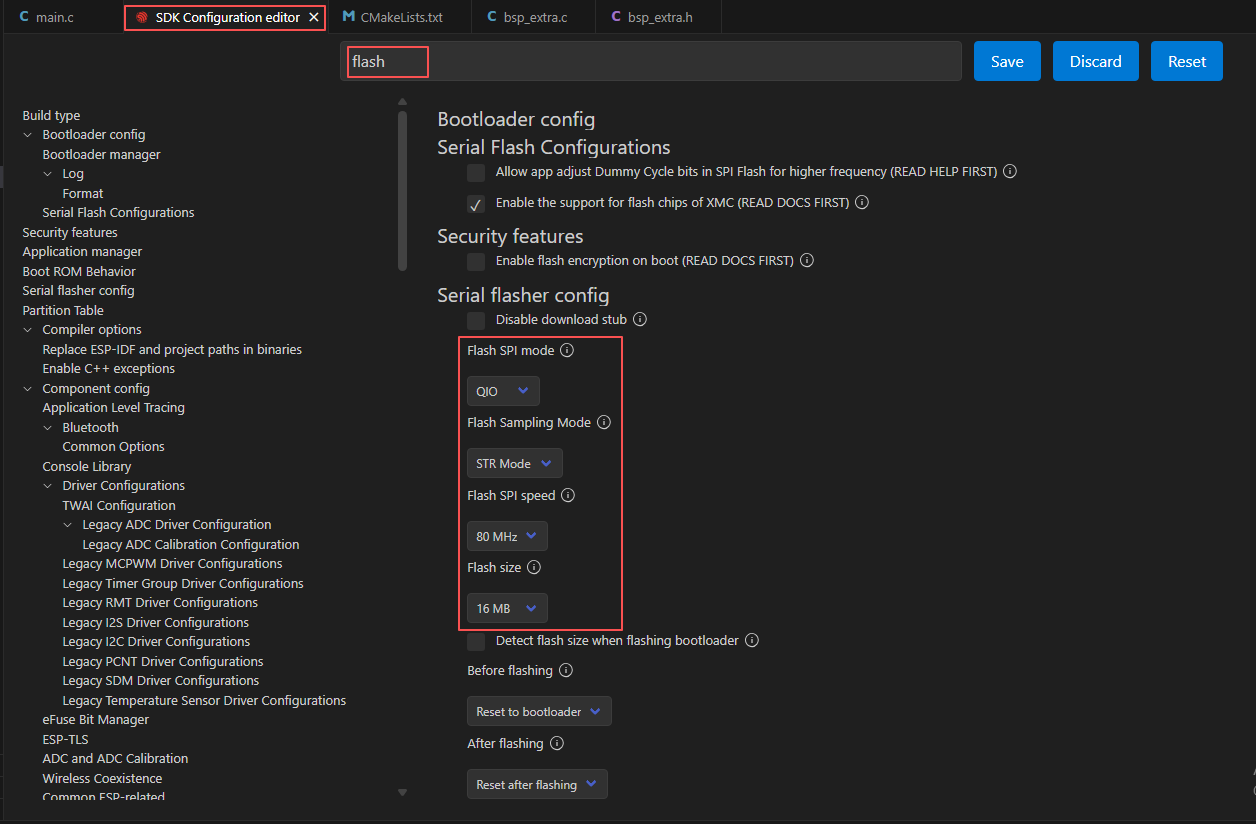
Search for flash and ensure Flash SPI mode: QIO; Flash Sampling Mode: STR Mode; Flash SPI speed: 80 MHz; Flash size: 16 MB.
In the LWIP configuration of the AP+STA (softap_sta) project, enable Enable IP forwarding, Enable NAT, and Enable NAT Port Mapping so that hotspot clients can route network traffic through the Station side.

Next, refer to "4. Software Operation Steps" in
Lesson07_Turn_on_the_Screento complete the detailed SDK configuration; the relevant configuration methods have been covered in Lesson 7.
After verifying that the configuration is correct, click Save in the upper right corner; confirm that the changes have been saved, then run Build to compile.
Click Full Clean to clear the cache left over from the previous compilation. Run this operation after the first compilation, switching project configurations, or modifying SDK parameters to prevent old configurations from affecting new compilation results.

Click Build to compile the project.

After connecting the development board, click Select Port to Use to choose the corresponding serial port, then click Flash to flash the firmware. After flashing, click Monitor to observe the connection logs. Press Ctrl + ] to exit the monitor.

Open the ESP32_P4-softAP project (AP mode) and, following steps 2 through 9, confirm the target chip, WiFi parameters, Hosted, and Flash configurations, then sequentially execute Full Clean, Build, Flash, and Monitor.
After flashing is complete, the serial port should show that AP mode is ready; once a phone or computer connects to the ELECROW hotspot, the serial port will print the client join and its IP information. This mode only provides a local hotspot and does not connect to an upstream network, so clients cannot access the internet by default.


Open the ESP32_P4-softap_sta project (AP+STA mode) and, following steps 2 through 9, confirm the target chip, WiFi parameters, Hosted, Flash, and NAPT configurations, then sequentially execute Full Clean, Build, Flash, and Monitor.
After flashing is complete, the serial port should first show that the STA has connected to the upstream WiFi, then show that the AP has started; once a phone or computer connects to the ELECROW hotspot, the serial port will print the client IP and can access the internet via NAPT.


Finally, you can use the one-click operation button in the ESP-IDF status bar to sequentially execute compilation, flashing, and opening the serial monitor. Use this only after the project configuration, serial port, and code have all been verified; if you need to troubleshoot, you should still follow the steps above one by one.

5. Hardware Operation Steps
Connect the ESP32-P4 development board to the computer using a USB data cable.
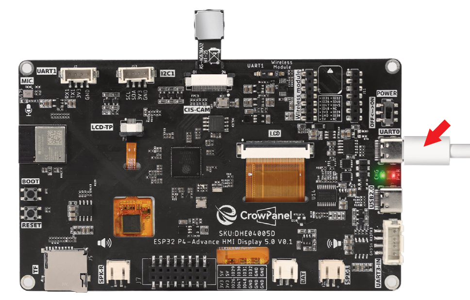
The ESP32-C6 module is already mounted on the board.

After flashing the Station mode, observe whether the serial port prints got ip:192.168.x.x to confirm that it has connected to the router and obtained an IP.
After flashing the softAP mode, use a phone to search for the WiFi hotspot ELECROW, enter the password 12345678 to connect, and the serial port should print station join.
After flashing the AP+STA mode, the STA connects to the router and obtains an IP while the AP hotspot is simultaneously available; after a phone connects to the AP, it should be able to access the internet (via NAPT forwarding), and the serial port will print both AP and STA logs.

6. Key Code Explanation
s_wifi_event_group = xEventGroupCreate();
esp_netif_init();
esp_event_loop_create_default();
esp_wifi_init(&cfg);
esp_wifi_set_mode(WIFI_MODE_STA);
esp_wifi_set_config(WIFI_IF_STA, &wifi_config);
esp_wifi_start();
The station project initializes NVS, creates the TCP/IP and default event-loop resources, registers Wi-Fi/IP event handlers, and configures the STA credentials and authentication threshold. WIFI_EVENT_STA_START begins the connection, disconnect events retry up to the configured limit, and IP_EVENT_STA_GOT_IP stores the success state.
EventBits_t bits = xEventGroupWaitBits(
    s_wifi_event_group,
    WIFI_CONNECTED_BIT | WIFI_FAIL_BIT,
    pdFALSE, pdFALSE, portMAX_DELAY);
The event group converts asynchronous callbacks into a blocking startup result: the station example sets WIFI_CONNECTED_BIT after obtaining an IP and WIFI_FAIL_BIT after exhausting retries. The AP+STA project uses WIFI_MODE_APSTA, creates both network interfaces, advertises the ELECROW access point, copies the upstream STA DNS server to the AP DHCP server, selects STA as the default route, and calls esp_netif_napt_enable() so hotspot clients can share the STA connection.
7. Experimental Observations
After the station project succeeds, the serial port prints the acquired IP; the softAP project can detect the ELECROW hotspot and report client join/leave events; the APSTA project simultaneously connects to elecrow888 and provides the ELECROW hotspot. When the password is incorrect or the network is unavailable, the serial port outputs retry and final failure logs.