5inch_P4_Micropython_01_LVGL_Control_LED: Controlling LED On/Off via the LVGL Interface
1. Course Introduction
This lesson uses the CrowPanel Advanced 5-inch ESP32-P4 HMI, the 5-inch dedicated MicroPython firmware, LVGL, the Thonny IDE, the DHT20, and the onboard STC8 controller to build an 800 × 480 touch interface. The program directly creates temperature, humidity, ON, and OFF widgets using the LVGL Python API; after a button is touched, GPIO48 outputs high or low logic levels to turn the LED on or off.
Compatibility note: The 5-inch display uses RGB565 16-bit. The source Word document explicitly states that MicroPython projects in SquareLine Studio version 9.0 and above currently support only 32-bit, so this lesson does not use SquareLine Studio and does not follow the
ui_images.pyexport workflow from the 7-inch lesson.
2. Learning Objectives
- Be able to flash the 5-inch dedicated firmware to the ESP32-P4 and determine whether the connection is successful via
boot.py. - Be able to upload
inch5_test.py,dht20.py, andstc8h1kxx.py, and run the code to directly create the LVGL interface. - Be able to explain the relationships among RGB565 display, GT911 touch, STC8 backlight control, DHT20 readings, and GPIO48 LED control.
- Be able to evaluate experimental results based on the LCD, LED, touch response, and Shell logs, and troubleshoot common faults.
3. What You Need to Prepare
-
1 × CrowPanel Advanced 5-inch ESP32-P4 HMI AI Display, with a screen resolution of 800 × 480 and RGB565 16-bit.
-
1 × USB data cable that supports data transfer; a charging-only cable cannot flash firmware or transfer files.
-
A Windows PC and the Thonny IDE; if the latest version fails to flash or run correctly, use Thonny 4.1.7, which has been verified by the source document.
-
The 5-inch dedicated firmware
lvgl_micropy_ESP32_GENERIC_P4-C6_WIFI-16_ELECROW_INCH5_V1_0.bin; do not substitute the 7/9/10-inch firmware. -
Close any software occupying the serial port before flashing; power off before plugging or unplugging the SD card, speaker, or other hardware.
-
inch5_test.py,dht20.py,stc8h1kxx.py, and the 5-inch firmware from this lesson's directory. -
A DHT20 temperature and humidity sensor; the main program will initialize this sensor on the I2C bus.
-
lcd_bus,rgb_display, andgt911are already included in the specified firmware, so there is no need to upload files with the same names separately.
4. Software Operation Steps
Visit the Thonny official website to download the Windows installer; if the latest version cannot flash reliably, use 4.1.7.
Please visit https://thonny.org/ and download the corresponding software version (the Windows version is used as an example here).
Note:
If the latest version of the editor fails to upload firmware or compile successfully, please try the stable version 4.1.7.
Download link: https://github.com/thonny/thonny/releases/tag/v4.1.7

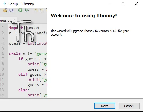
Double-click the downloaded .exe file and complete the installation by following the setup wizard, then launch Thonny.
Connect the CrowPanel Advanced 5-inch ESP32-P4 HMI AI Display to your computer.

After connecting the development board, open Tools → Options in Thonny.

On the Interpreter page, select MicroPython (ESP32) and the correct serial port, then click Install or update MicroPython (esptool).

Open the three-horizontal-line menu, select the local MicroPython image, and load lvgl_micropy_ESP32_GENERIC_P4-C6_WIFI-16_ELECROW_INCH5_V1_0.bin.
Click the icon with three horizontal lines, then click " Select local MicroPython image " ,
select "lvgl_micropy_ESP32_GENERIC_P4-C6_WIFI-16_ELECROW_INCH5_V1_0" and install it.
Please click the following link to download the bin file: https://github.com/Elecrow-RD/-CrowPanel-Advanced-5inch-ESP32-P4-HMI-AI-Display-800x480-IPS-Touch-Screen/tree/master/example/V1.0/Micropython

For the target chip, select ESP32-P4; do not select other ESP32 models with similar names.

After verifying the serial port, chip, and local firmware, click Install; do not unplug the cable during flashing.

Wait for the erase and write progress to complete; brief unresponsiveness of the interface during this period is normal.

Confirm that the installation window shows a success message with no red error information.

Click Close to close the firmware installation window.

Return to the Options window and click OK to reconnect the interpreter to the development board.

Confirm that MicroPython device and boot.py appear in the lower-left corner, indicating that the firmware and serial connection are successful.

If the device file area is not displayed, open View → Files.

In This computer, locate this lesson's files, then right-click or use the upload command to send the files to the device root directory.

Verify that inch5_test.py, dht20.py, and stc8h1kxx.py already exist on the device; the file names must match the import statements.
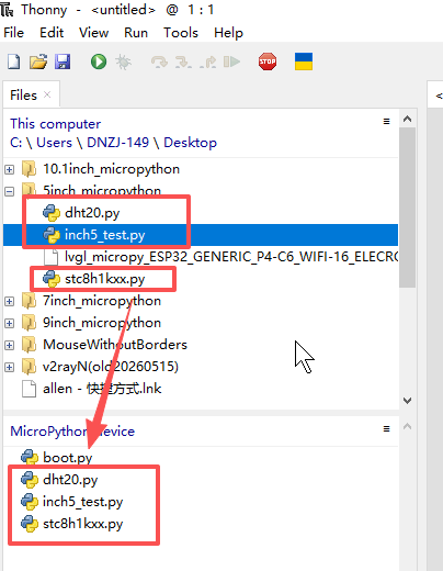
Double-click inch5_test.py on the device to open the main program.

Click the green Run button and observe the I2C, backlight, RGB bus, and touch initialization logs in the Shell.

Confirm that the 800 × 480 interface is displayed in full, the temperature and humidity update every second, and the GPIO48 LED turns on and off respectively when the ON and OFF buttons are touched.

5. Hardware Operation Steps
Connect the DHT20 and LED

If you want to control the LED, you need to switch this switch to the left side of UART1
Then, switch the toggle switch on the 5-inch Advance-P4 to the UART1 position. Only in this way can the UART1 interface be used.

This is the design on the hardware side.

Switch to UART1 port:
Among the three interfaces shown in the figure, only the UART1 interface can be used at this time.
Alternatively, the expansion header at the bottom can also be used.
That is, either the UART1 interface or the expansion header can be used, but not both.
Switch to Wireless Module port:
Among the three interfaces shown in the figure, only the wireless module can be used at this time.
Alternatively, the expansion header at the bottom can also be used.
That is, either the wireless module or the expansion header can be used, but not both.
Summary:
The UART1 interface and the Wireless Module can only be used when switched to the corresponding port.
The expansion header at the bottom can be used regardless of the position of the mode switch, but it cannot be used simultaneously with the above interfaces. (When used simultaneously, only one of the three interfaces can be selected.)
Power off and check the sensor and experimental cables, connect to the PC using a USB cable that supports data transfer, then power on.
Run the program and observe the 5-inch LCD, the DHT20 readings, and the GPIO48 LED; the LED should turn on and off respectively when ON and OFF are touched.

Safety note: Use a finger to operate the capacitive touch screen; do not touch the screen with sharp or metallic objects; do not unplug the USB cable during flashing or file upload.
6. Key Code Explanation
6.1 5-inch Display Parameters and RGB565
The display object must use 800 × 480 and lv.COLOR_FORMAT.RGB565. RGB565 carries color over 16 data lines; if the resolution, pixel clock, or front/back porch parameters are incorrect, issues such as offset, jitter, garbled display, or no image may occur. When troubleshooting a black screen, first check whether the STC8 has turned on the LCD power and set the backlight PWM, then inspect the RGB bus.
6.2 I2C and Device Initialization
The program first creates the I2C bus using I2C.Bus() and sets I2C_BUS = 0, SDA as GPIO45, SCL as GPIO46, and the communication frequency to 400_000, which is 400 kHz. After initialization, it scans the connected devices on the current I2C bus using i2c_bus.scan() and prints out the hexadecimal addresses for verification, to confirm whether devices such as STC8, GT911, and DHT20 can communicate normally.
I2C_BUS = 0
I2C_SDA_PIN = 45
I2C_SCL_PIN = 46
I2C_FREQ = 400_000

i2c_bus = I2C.Bus(
    host=I2C_BUS,
    sda=I2C_SDA_PIN,
    scl=I2C_SCL_PIN,
    freq=I2C_FREQ
)
Subsequently, the program uses I2C.Device() to create device objects for STC8 and DHT20 on the same I2C bus. By specifying the corresponding I2C address dev_id and register bit width reg_bits, MicroPython is informed of how to access these devices. Finally, these I2C device objects are passed to STC8H1KXX() and DHT20() drivers to complete the specific device initialization.
i2c_stc8 = I2C.Device(
    bus=i2c_bus,
    dev_id=STC8H1KXX.I2C_ADDR,
    reg_bits=8
)

i2c_dht20 = I2C.Device(
    bus=i2c_bus,
    dev_id=DHT20.I2C_ADDR,
    reg_bits=8
)

stc8 = STC8H1KXX(i2c_stc8)
dht20 = DHT20(i2c_dht20)
6.3 Button Events Controlling GPIO48
The two callbacks run when LVGL dispatches click events. If the interface displays normally but the LED does not change, check whether the button has registered the corresponding callback and whether GPIO48 is occupied by another program. The source Word document incorrectly describes the OFF button's text as LED.value(1); the actual accompanying code is LED.value(0), so this lesson follows the code behavior and corrects it.
LED = Pin(48, Pin.OUT)

def Button1_eventhandler(event_struct):
    if event_struct.get_code() == lv.EVENT.CLICKED:
        LED.value(1)

def Button2_eventhandler(event_struct):
    if event_struct.get_code() == lv.EVENT.CLICKED:
        LED.value(0)
6.4 UI and Main Loop
create_lvgl_ui() directly creates a light-green screen, a yellow ON button, a gray OFF button, and blue temperature/humidity labels, without relying on SquareLine Studio resources. The main loop reads the DHT20 every 1000 ms and calls lv.tick_inc(10) and lv.timer_handler() every 10 ms; this timing approach prevents sensor reads from blocking touch refresh over the long term.
6.5 Companion File Responsibilities
inch5_test.py is the main program, dht20.py parses the raw temperature and humidity data, stc8h1kxx.py controls board-level functions such as the LCD backlight, and the .bin file provides the 5-inch display, touch, and MicroPython runtime environment.
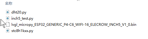
dht20.py : The driver file for the temperature and humidity sensor .
stc8h1kxx.py: Used to communicate with the STC8 chip via the I2C bus to implement functions such as GPIO control and PWM dimming.
lvgl_micropy_ESP32_GENERIC_P4-C6_WIFI-16_ELECROW_INCH5_V1_0.bin :
Elecrow pre-packaged firmware that allows your Python scripts to display DHT20 sensor values on the LCD of the "CrowPanel Advanced 5 inch ESP32-P4 HMI" and control LED light switching via touch.
inch5_test.py : This is the main program that runs the entire example; we will mainly explain this code file.
7. Experimental Results
After reset, the Shell prints I2C scan, backlight-on, RGB bus registration, and GT911 initialization messages; the LCD displays the 800 × 480 interface. The temperature and humidity refresh approximately once per second; after touching ON, the GPIO48 LED lights up, and after touching OFF, it turns off. When continuously clicked and run for several minutes, the interface should not freeze, display garbled output, or restart. Common Issues: When the screen is black, first check whether the INCH5 firmware has been flashed and review the STC8 backlight log; when touch is unresponsive, check the GPIO36, GPIO42, and GT911 initialization; when the DHT20 malfunctions, check the I2C scan results; when an upload fails, confirm that the serial port is not in use and that the USB cable supports data transfer.