Lesson01_RotaryScreen_LVGL: ESP32-S3 Rotary Display, Touch, and Encoder Interaction
1. Lesson Introduction
This lesson uses Arduino IDE 2.3.6 and ESP32 Arduino Core 3.3.8 to drive an ESP32-S3 1.46-inch 360 × 360 rotary display. The project controls the ST77961 LCD through LovyanGFX, reads touch coordinates through the CST816T, implements the graphical interface using LVGL 9.1.0 and a UI exported from SquareLine Studio 1.5.3, and uses separate FreeRTOS tasks to handle the rotary encoder and eight NeoPixel RGB LEDs.
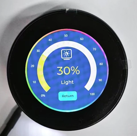
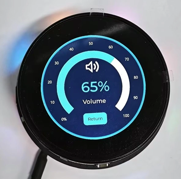
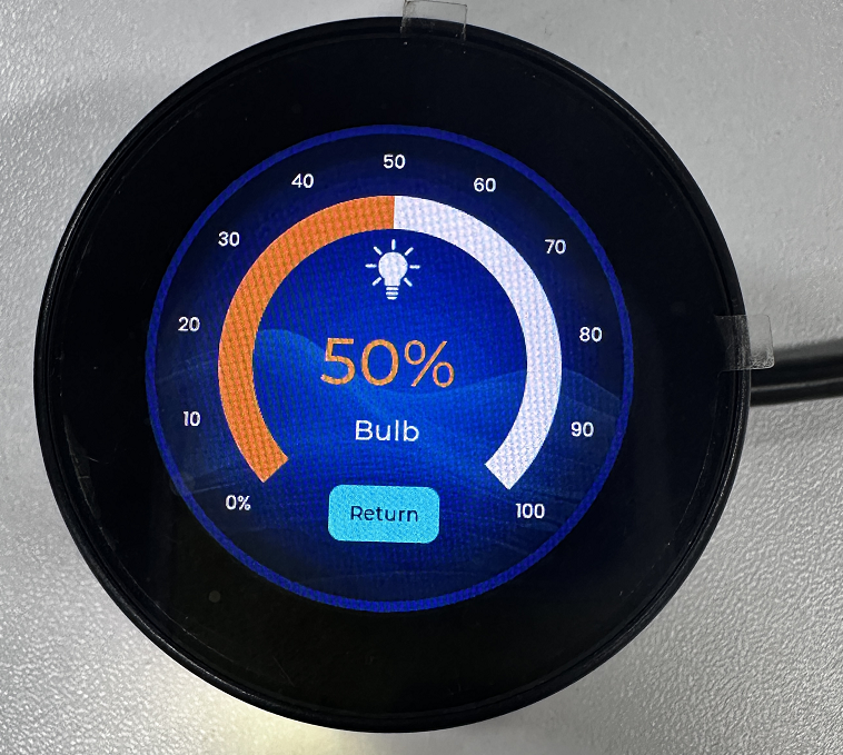
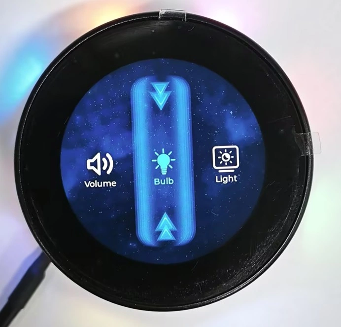
After the program is uploaded and the board is reset, the screen first displays a startup page with a rotating icon, followed by a fade-in transition to the main menu. The main menu contains three options: Volume, Bulb, and Light. Rotate the knob to switch the current selection, and single-click it to open the corresponding detail page. On a detail page, rotate the knob or touch the arc control to adjust the value in 5% increments. Double-click the knob or touch the Return button to return to the main menu. The Bulb value synchronously controls the PWM output on GPIO 43, while the Light value synchronously changes the screen backlight brightness. At the same time, the eight onboard RGB LEDs cycle through running-light, flashing, and multicolor breathing effects.
The focus of this lesson is not to introduce a particular LVGL API in isolation, but to verify the entire signal chain—from display power, SPI DMA screen updates, I2C touch input, and rotary encoder input to LVGL page interaction and PWM output. Note that the Volume page currently changes only the displayed value and is not connected to audio playback functionality. The touch-coordinate debugging macro is disabled by default, so touch coordinates are not printed to the serial port.
2. Learning Objectives
- Configure the ESP32-S3, 16 MB Flash, OPI PSRAM, and Arduino Core version according to the project requirements.
- Explain the data relationships among the ST77961 display, CST816T touch controller, LVGL flush callback, and SquareLine UI.
- Compile and upload the project, and determine whether the display chain is working correctly by checking the startup page, main menu, and detail pages.
- Use rotation, single-click, double-click, and touch operations to select pages, adjust values, and return to the previous page.
- Determine whether each function is working correctly based on UI values, GPIO 43 PWM output, screen backlight, NeoPixel lighting effects, and serial logs.
3. Required Materials
3.1 Hardware
- ESP32-S3 1.46-inch 360 × 360 rotary display development board, 1.
- USB data cable that supports data transfer, 1.
- Computer, 1.
This project uses the onboard ST77961 LCD, CST816T touch controller, rotary encoder, encoder push button, and eight NeoPixel RGB LEDs. No external modules are required for these components.
3.2 Software and Versions
- Arduino IDE 2.3.6.
- ESP32 Arduino Core 3.3.8.
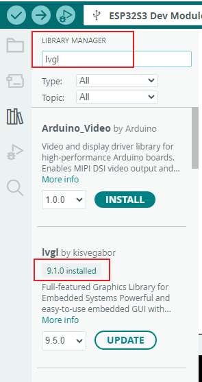
- LVGL 9.1.0.
- LovyanGFX 1.2.7.
- Adafruit NeoPixel 1.15.1.
- CST816T 1.5.1.
- Adafruit BusIO 1.17.4, Adafruit GFX Library 1.12.4, UI files, and other dependencies are included in the project.
3.3 Required Project Files
RotaryScreen_1_46_Code_Core3_LVGL9.ino: Main program.RotaryScreen_1_46.h: Pin assignments, display bus, panel parameters, and global state configuration.libraries/UI/: LVGL 9.1 UI, image assets, and page code exported from SquareLine Studio.libraries/lvgl/,libraries/LovyanGFX/,libraries/cst816t/,libraries/Adafruit_NeoPixel/: Project dependencies.
Do not copy only the .ino file. If the header file in the same directory or libraries/UI/ is missing, the project cannot display the UI used in this lesson. Mixing in another major LVGL version may also cause API or generated-code incompatibilities.
4. Software Procedure
Arduino software installation guide: https://www.elecrow.com/wiki/Get_Started_with_Arduino_IDE.html
Select ESP32 version 3.3.8. Code repository: https://github.com/Elecrow-RD/CrowPanel-1.46inch-HMI-ESP32-Rotary-Display/tree/master/example/V1.0/Arduino/RotaryScreen_1_46_Code_Core3_LVGL9
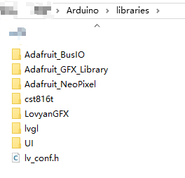
Step01: Copy the complete RotaryScreen_1_46_Code_Core3_LVGL9 project to a working directory without special permission restrictions. Confirm that the .ino and .h files remain in the same project directory. Place the files in libraries/ in the Arduino IDE library directory. 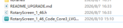
Step02: Start Arduino IDE 2.3.6, select File > Open, and open RotaryScreen_1_46_Code_Core3_LVGL9.ino. After opening it, both the main program and the header file in the same directory should be visible. 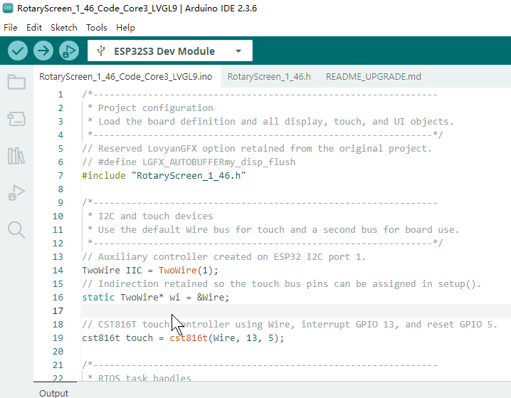
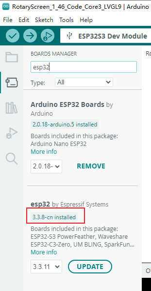
Step03: Open Boards Manager and install or confirm that esp32 by Espressif Systems is version 3.3.8. If other versions are also installed on the computer, use the version validated for this project.
Step04: Check the dependency versions: LVGL 9.1.0, LovyanGFX 1.2.7, Adafruit NeoPixel 1.15.1, and CST816T 1.5.1. If the project already includes the packaged dependencies, do not load other versions with the same names, as Arduino IDE may select the wrong libraries.
Step05: Expand the Partition Table
Because the rotary screen's Arduino IDE code is combined with the UI files generated by SquareLine Studio, the overall project is fairly large, and the partition table provided in the current ESP32 library is insufficient to support running the entire project, so the partition table needs to be expanded.
You can first download the partition table content we provide:
After downloading the partition table file, open your local ESP32 download path.
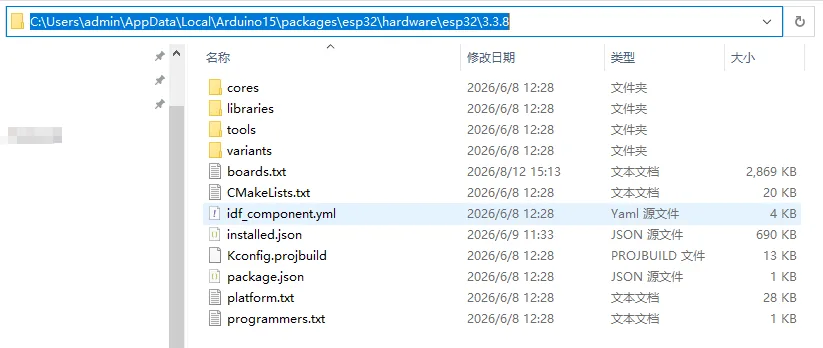
Open the boards.txt file in the partition table file we provide at the link above, and copy its contents.
esp32s3.menu.PartitionScheme.elecrow_s3=elecrow_s3 (10.0MB APP with OTA/1.31MB SPIFFS)
esp32s3.menu.PartitionScheme.elecrow_s3.build.partitions=elecrow_s3
esp32s3.menu.PartitionScheme.elecrow_s3.upload.maximum_size=10485760
Then open the boards.txt in your local path.
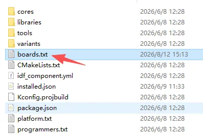
Copy the content above to the corresponding location; do not place it arbitrarily—refer to the position shown in the figure.
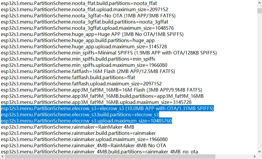
Then go to this path and copy the partition table file we provide into it.
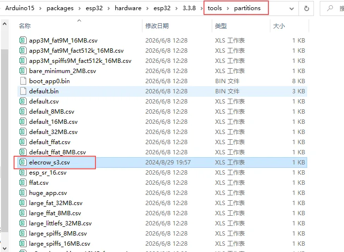
Then close all your Arduino IDE programs, and we recommend restarting the computer.
**Step06:**Open the Code, Set Parameters, and Upload
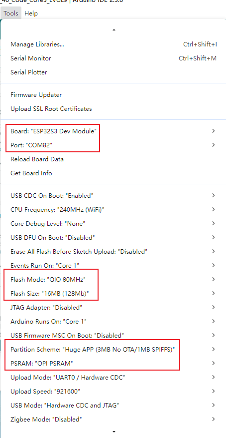
Set the following parameters in the Tools menu: CPU Frequency to 240 MHz (WiFi), Flash Mode to QIO 80 MHz, Flash Size to 16 MB (128 Mb), Partition Scheme to Huge APP (3 MB No OTA / 1 MB SPIFFS), PSRAM to OPI PSRAM, USB CDC On Boot to Disabled, Upload Mode to UART0 / Hardware CDC, and Upload Speed to 921600.
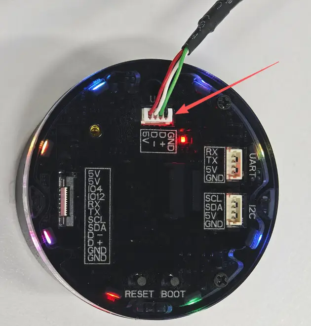
Step07: Connect the rotary display using the factory-supplied USB data cable, and select the newly detected serial port under Tools > Port. Click Verify. After compilation is complete, the console should not show errors indicating that lvgl.h, LovyanGFX.h, cst816t.h, or ui.h is missing.
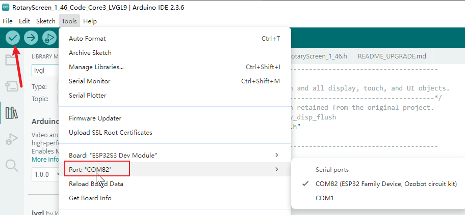
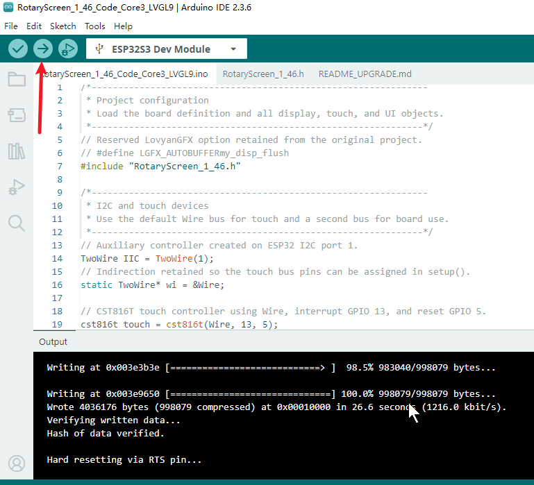
Step08: Click Upload. If the development board does not automatically enter download mode, follow the board-specific download procedure to enter Boot mode and try again. After the upload is complete, open Serial Monitor, set the baud rate to 115200, and then reset the development board.
5. Hardware Procedure
Step01: With the development board powered off, inspect the USB port, screen, knob, and surrounding RGB LEDs for damage. Confirm that no metallic foreign objects could cause a short circuit.Use a USB cable that supports data transfer to connect the rotary display to the computer.
Step02: After powering it on, observe the power indicator and screen area. Do not repeatedly connect and disconnect the USB cable immediately. Perform basic operations and verify whether they meet the requirements.
6. Key Code Explanations
6.1 Board Startup and Pin Preparation
pinMode(1, OUTPUT); digitalWrite(1, HIGH);
pinMode(2, OUTPUT); digitalWrite(2, HIGH);
pinMode(17, OUTPUT); digitalWrite(17, HIGH);
pinMode(ENCODER_A_PIN, INPUT);
pinMode(ENCODER_B_PIN, INPUT);
pinMode(SWITCH_PIN, INPUT_PULLUP);
attachInterrupt(digitalPinToInterrupt(SWITCH_PIN), buttonISR, FALLING);
In setup(), GPIO1 and GPIO2 enable the display power rails, while GPIO17 enables the NeoPixel ring. The encoder channels are configured as inputs, the push button uses its internal pull-up resistor, and a falling edge triggers buttonISR().
6.2 LCD, LVGL, and DMA Display Flush
const uint32_t screenWidth  = 360;
const uint32_t screenHeight = 360;

size_t buffer_size = screenWidth * screenHeight * 2;
buf = (uint8_t *)heap_caps_malloc(buffer_size, MALLOC_CAP_SPIRAM | MALLOC_CAP_8BIT);
buf1 = (uint8_t *)heap_caps_malloc(buffer_size, MALLOC_CAP_SPIRAM | MALLOC_CAP_8BIT);

display = lv_display_create(screenWidth, screenHeight);
lv_display_set_color_format(display, LV_COLOR_FORMAT_RGB565);
lv_display_set_flush_cb(display, my_disp_flush);
lv_display_set_buffers(display, buf, buf1, buffer_size, LV_DISPLAY_RENDER_MODE_PARTIAL);

void my_disp_flush(lv_display_t *disp, const lv_area_t *area, uint8_t *px_map) {
  if (gfx.getStartCount() > 0) gfx.endWrite();
  gfx.pushImageDMA(area->x1, area->y1,
                   area->x2 - area->x1 + 1,
                   area->y2 - area->y1 + 1,
                   (lgfx::rgb565_t *)px_map);
  gfx.waitDMA();
  lv_display_flush_ready(disp);
}
The display is 360 × 360 pixels. RGB565 uses two bytes per pixel, so each full buffer needs about 259,200 bytes. Two buffers are allocated in PSRAM to preserve internal RAM. LVGL calls my_disp_flush() whenever a region needs to be redrawn; LovyanGFX transfers that rectangle through SPI DMA, waits for the transfer to finish, and then releases the buffer with lv_display_flush_ready(). Allocation errors usually indicate incorrect PSRAM or color-depth settings.
6.3 CST816T Touch Input
wi->setPins(6,7);
wi->begin();
touch.begin(mode_touch);

lv_indev_t *indev = lv_indev_create();
lv_indev_set_type(indev, LV_INDEV_TYPE_POINTER);
lv_indev_set_read_cb(indev, my_touchpad_read);

void my_touchpad_read(lv_indev_t *indev, lv_indev_data_t *data) {
  if (touch.available()) {
    data->state = LV_INDEV_STATE_PRESSED;
    if (touch.x == 0 && touch.y == 0) return;
    data->point.x = touch.x;
    data->point.y = touch.y;
  } else {
    data->state = LV_INDEV_STATE_RELEASED;
  }
}
The CST816T controller uses GPIO6 and GPIO7 for I2C. It is registered as an LVGL pointer device, so LVGL calls my_touchpad_read(). A valid sample reports coordinates and a pressed state; when no sample is available, the function reports the released state. The (0,0) sample is ignored.
6.4 Creating the UI and Arc Controls
ui_init();

lv_obj_set_style_arc_image_src(ui_VolumeArc, NULL, LV_PART_MAIN);
lv_obj_set_style_arc_image_src(ui_VolumeArc, NULL, LV_PART_INDICATOR);
lv_obj_set_style_arc_color(ui_VolumeArc, lv_color_hex(0xFFFFFF), LV_PART_MAIN);
lv_obj_set_style_arc_color(ui_VolumeArc, lv_color_hex(0x33DCFF), LV_PART_INDICATOR);

lv_obj_set_style_arc_color(ui_BulbArc, lv_color_hex(0xFFFFFF), LV_PART_MAIN);
lv_obj_set_style_arc_color(ui_BulbArc, lv_color_hex(0xFF8A33), LV_PART_INDICATOR);

lv_obj_set_style_arc_color(ui_LightArc, lv_color_hex(0xFFFFFF), LV_PART_MAIN);
lv_obj_set_style_arc_color(ui_LightArc, lv_color_hex(0xFFE83D), LV_PART_INDICATOR);

lv_arc_set_range(ui_VolumeArc, 0, 100);
lv_arc_set_range(ui_BulbArc,   0, 100);
lv_arc_set_range(ui_LightArc,  0, 100);

lv_arc_set_value(ui_VolumeArc, 50);
lv_arc_set_value(ui_BulbArc,   50);
lv_arc_set_value(ui_LightArc,  50);
ui_init() creates the startup page, the main menu, and the three detail pages generated by SquareLine Studio. All three arcs use a 0–100 range and start at 50. Because image-based arc textures are unreliable with this LVGL 9.1 rendering path, setup() disables those textures and draws native arcs: white tracks with blue, orange, and yellow indicator colors.
6.5 Percentage Labels and PWM Outputs
int value = lv_arc_get_value(arc);
char bulbText[8];
snprintf(bulbText, sizeof(bulbText), value == 100 ? "%d%%" : " %d%%", value);
lv_label_set_text(ui_BulbNum, bulbText);

int pwm_value = (value * 255) / 100;
ledcWrite(BULB_LED_PIN, pwm_value);
This excerpt from bulb_arc_event_cb() reads the Bulb arc value, formats the percentage label, converts the 0–100 value to the 8-bit PWM range, and writes the result to BULB_LED_PIN (GPIO43).
6.6 Encoder Task, Event Queue, and Page Switching
encoderActionQueue = xQueueCreate(16, sizeof(EncoderAction));
xTaskCreatePinnedToCore(encTask, "ENC", 2048, NULL, 1, &encTaskHandle, 0);

EncoderAction action;
while (encoderActionQueue &&
       xQueueReceive(encoderActionQueue, &action, 0) == pdTRUE) {
  handleEncoderAction(action);
}
The queue stores up to 16 EncoderAction items, and encTask() runs on Core 0. The Arduino loop receives each queued action and passes it to handleEncoderAction(). This keeps the task that reads the encoder separate from the code that updates LVGL.
6.7 Main Loop and NeoPixel Effects
led.setBrightness(25);
xTaskCreatePinnedToCore(ledTestTask, "LED Test", 2048, NULL, 1,
                        &ledTestTaskHandle, 0);

EncoderAction action;
while (encoderActionQueue &&
       xQueueReceive(encoderActionQueue, &action, 0) == pdTRUE) {
  handleEncoderAction(action);
}

lv_timer_handler();
vTaskDelay(pdMS_TO_TICKS(5));
The NeoPixel brightness is set to 25, and ledTestTask() runs separately on Core 0. In loop(), queued encoder actions are handled before lv_timer_handler() processes LVGL timers, input, events, and redraws. The 5 ms delay yields processor time before the next loop cycle.
7. UI Asset Integration Process
This project provides UI C files already exported from SquareLine Studio 1.5.3, but it does not include the original editable SquareLine project. Therefore, this section only explains how the existing assets are integrated and does not fabricate the original control-design process. If the original project becomes available later, complete creation screenshots should be added based on a resolution of 360 × 360, LVGL 9.1.0, and a 16-bit color depth.
UI project repository: https://github.com/Elecrow-RD/CrowPanel-1.46inch-HMI-ESP32-Rotary-Display/tree/master/example/V1.0/Arduino/1_46_SquareLine_Studio_Project
SquareLine Studio operating guide: https://www.elecrow.com/wiki/Get_Started_with_SquareLine_Studio.html
Open the provided project using SquareLine Studio. Confirm the LVGL version and dimensions. 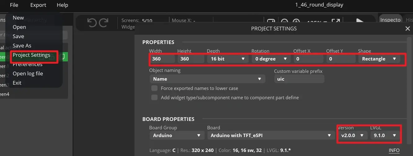
8. Expected Results
8.1 Power-On and Startup
- After USB power is applied, GPIO 1 and GPIO 2 are driven high to enable screen power, while GPIO 40 is driven low to illuminate the active-low power indicator.
- After the LCD is reset, it is first filled with black, and the backlight is enabled at approximately a 50% duty cycle.
- The Screen0 startup page appears, and the center icon performs multiple rotation animations. When they are complete, the UI transitions to the main menu with a fade-in effect.
- If the serial port outputs
Failed to allocate for LVGL buf!orFailed to allocate for LVGL buf1!, PSRAM buffer allocation has failed, and the experiment cannot be considered successful.
8.2 Main Menu and Knob
- The main menu displays three options:
Volume,Bulb, andLight. The middle option,Bulb, is selected initially. - When the knob is rotated, the blue selection moves among the three options and does not move beyond the first or last item.
- The serial port outputs content similar to the following. The specific direction text depends on the physical installation orientation of the knob:
- After the knob is single-clicked, the program waits for the double-click detection window to expire before opening the currently selected detail page. Double-clicking returns from any detail page to the main menu.
8.3 Three Detail Pages
-
Volume: The initial value is 50%. The knob or touch input can adjust it from 0% to 100%. It only changes the UI and does not produce sound. -
Bulb: The initial displayed value is 50%. When the value changes, the GPIO 43 PWM output changes synchronously. When the program initializes GPIO 43, the raw PWM value written is 50. It is not converted from the percentage to the 0–255 range until the Arc callback is triggered for the first time. -
Light: The initial displayed value is 50%. When the value changes, the GPIO 46 backlight PWM output changes synchronously. At 0%, the screen may appear completely black, but the program may still be running. -
On all three pages, touch
Returnto go back. You cannot switch directly among the Volume, Bulb, and Light pages; you must return to the main menu first.
8.4 RGB LEDs and Stability
The eight NeoPixels should cycle through a white running-light effect, rapid multicolor flashing, a multicolor running-light effect, slow multicolor flashing, and a breathing effect. While the display animation, knob input, and LED animations are running simultaneously, the device should not reset repeatedly, remain stuck on one page for an extended period, or stop responding. The current code does not print touch coordinates by default; this is normal.
9. Common Issues and Troubleshooting
9.1 lvgl.h Is Not Found During Compilation or LVGL API Errors Occur
- Confirm that LVGL 9.1.0 is being used, rather than LVGL 8.x or another 9.x version.
- Confirm that Arduino IDE is not prioritizing another library with the same name in the sketchbook.
- Keep the complete
libraries/UI/directory; do not copy only the.inofile.
9.2 Compilation Reports an Incorrect Color Depth
The UI code requires LV_COLOR_DEPTH to be 16. Check the active lv_conf.h. Do not place the configuration file in a location Arduino cannot read, and do not retain multiple conflicting lv_conf.h files.
9.3 Upload Fails or the Port Cannot Be Found
- Replace the USB cable with one confirmed to support data transfer.
- Reselect
ESP32S3 Dev Moduleand the correct serial port. - If necessary, follow the board's Boot/Reset procedure to enter download mode.
- If 921600 is unstable, temporarily reduce the upload speed. This affects only the upload time and does not change program functionality.
9.4 The Screen Is Completely Black
Troubleshoot in the following order:
- Confirm that GPIO 1 and 2 have enabled screen power.
- Confirm that the GPIO 46 backlight has not been set to 0% from the Light page.
- Confirm the GPIO 14 reset timing and the ST77961 SPI pins.
- Check the serial output for PSRAM buffer-allocation failure messages.
- Confirm that both
ui_init()andlv_timer_handler()are executed.
9.5 The UI Is Visible but Touch Does Not Respond
- Check whether the CST816T uses the I2C bus on GPIO 6 and 7 and successfully calls
touch.begin(mode_touch). - Confirm that the LVGL input device has registered
my_touchpad_read(). - Do not touch the screen with sharp objects.
- To troubleshoot coordinates, temporarily enable
DEBUG_PRINTin the code and recompile. Restore the original setting after verification.
9.6 Knob Direction Is Reversed, Input Jumps, or Button Presses Are Triggered Incorrectly
- The direction text depends on the physical installation orientation. As long as menu selection and value changes are stable, operation is normal.
- Check the connections for GPIO 45, 42, and 41.
- A single-click must wait approximately 300 ms for the double-click detection window to expire. This behavior is intentional.
- Do not remove the debounce logic directly, or mechanical bouncing may be recognized as multiple clicks.