Lesson03_CrowPanel_Rotary_Backlight: Adjusting Screen Brightness with the Knob
1. Lesson Overview
This lesson adds CrowPanel knob input and PWM backlight control to the basic display pipeline from Lesson02. When the program starts, it sets the backlight to 50%, temporarily disables encoder events, and displays Screen Brightness and 50% in LVGL. After initialization is complete, each valid rotation step increases or decreases the brightness by 5%. The value is limited to the range of 0%–100%, and the percentage shown on the screen is updated accordingly.
Learners will complete end-to-end verification of the following pipeline: knob phase signals—ESPHome encoder count—brightness state—PWM output—LVGL label. This lesson does not use touch functionality, making it easier to independently verify the knob direction, debounce filtering, and backlight brightness changes.
2. Learning Objectives
- Explain how the A/B phases of a rotary encoder determine direction and count changes.
- Explain why
encoder_readyprevents knob events during startup. - Explain the conversion between integer brightness values from 0%–100% and PWM output values from 0.0–1.0.
- Verify that the dimming pipeline is working correctly based on the knob response, on-screen percentage, and actual backlight brightness.
- Troubleshoot common issues such as reversed direction, skipped steps, out-of-sync values, and unchanged backlight brightness.
3. Requirements
- A CrowPanel 1.46inch-HMI ESP32 Rotary Display.
- A USB cable that supports data transfer.
- ESPHome Device Builder 1.9.2.
- ESPHome 2026.7.4.
Code download link: Official Elecrow Lesson_Code
4. Software Procedure
Step01: Open ESPHome Device Builder 1.9.2 and confirm that its ESPHome Core version is 2026.7.4. If the versions do not match, upgrade or switch environments first to avoid differences in component syntax. 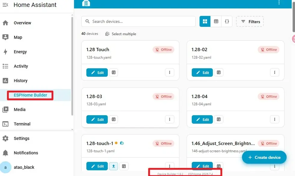 Step02: Create a new project, place the
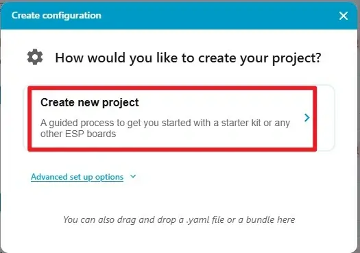
 146‑adjust‑screen‑brightness.yaml file in the ESPHome configuration directory, and open the corresponding configuration from the device list. The filename and esphome.name can be different, but device names must be unique on the same network.
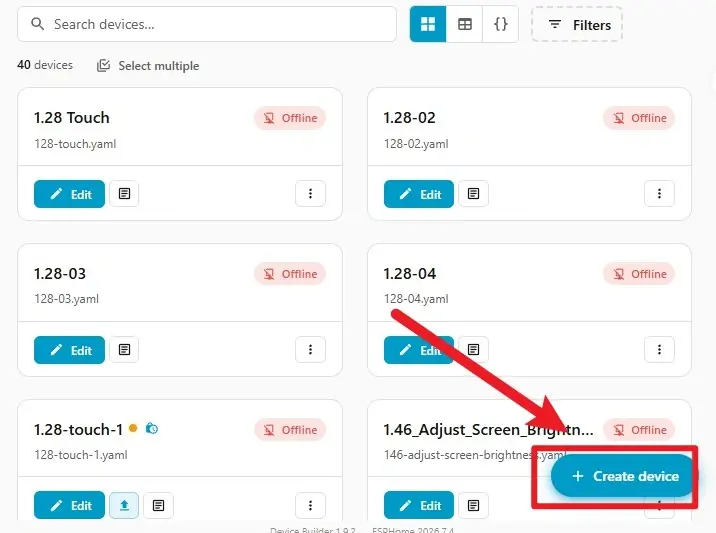
A. Click Create device to create a new project.
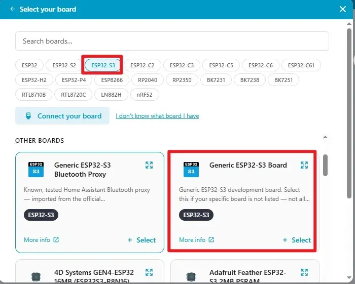
B. Select the esp32s3 microcontroller.
C. Name the project. Complete the project creation process.
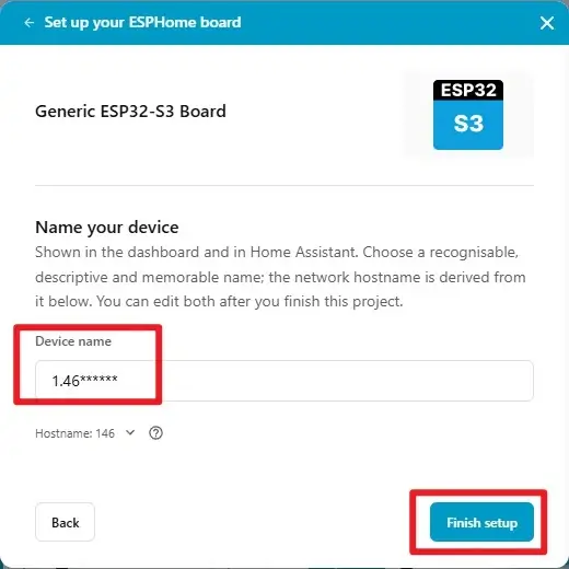
Step03: Copy the official code into the project. Do not copy the API key information. Use the newly generated API key. 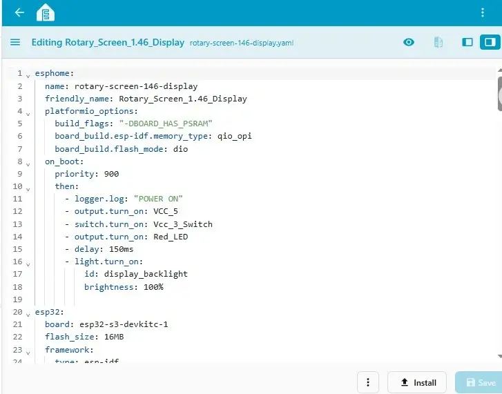
Step04: Modify the Wi-Fi settings. Click the three dots in the upper-right corner, then click secret. Enter your own Wi-Fi name and password.
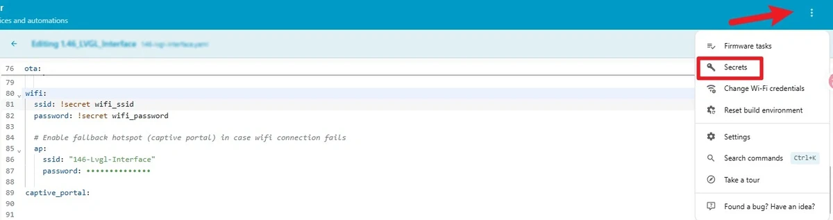
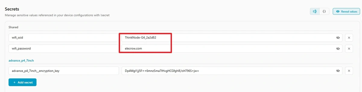

Step05: Click Install in the lower-right corner, select the USB installation method appropriate for the current environment, select the serial port corresponding to the CrowPanel, and complete compilation and flashing. After flashing is complete, open the log window. You should see the device startup messages and the POWER ON log entry.
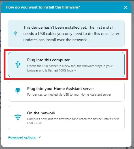
Step06: Wait for compilation to complete.
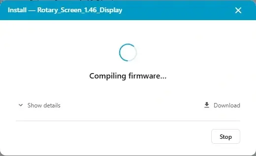
Step07: After compilation is complete, click flash to upload the firmware.
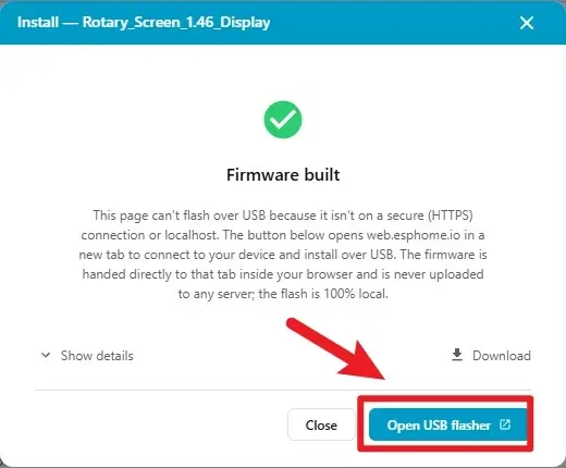
Step08: Select the connected serial port.
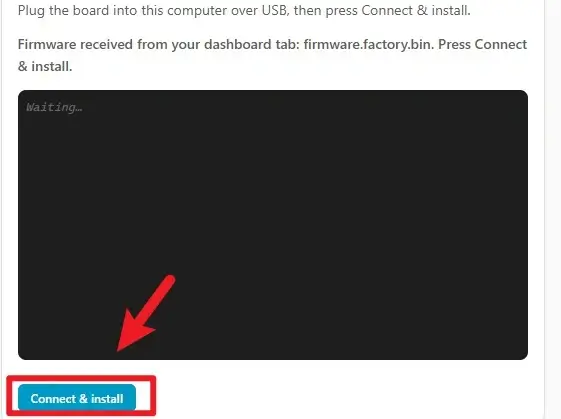
Step09: Click to connect to the corresponding serial port after confirming that the hardware is connected.
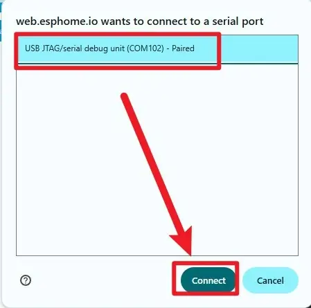
Step10: Wait for the download to complete.
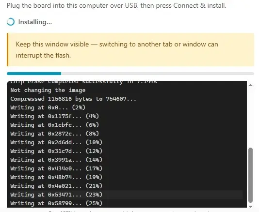
5. Hardware Procedure
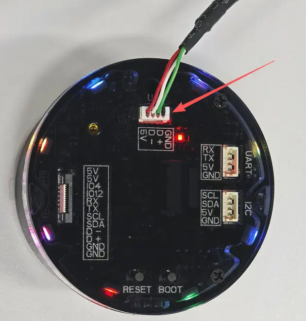
Step01: With the device powered off, check that the screen, knob housing, and USB port show no obvious signs of damage. Then use a USB cable that supports data transfer to connect the CrowPanel 1.46inch-HMI ESP32 Rotary Display to the computer.
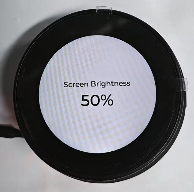
Step02: Rotate the knob back and forth around 0%, 50%, and 100%, and compare the on-screen text with the backlight intensity to verify that they are consistent. During operation, the device should not freeze, restart, or stop refreshing for an extended period.
6. Key Code Explanations
6.1 Disabling the Knob During Startup
This callback runs after the device starts and the display power supply has stabilized. It first disables knob processing, then resets the logical brightness and encoder count to a predictable baseline. If encoder events are accepted directly during startup, the initial count published by the component may be mistaken for user input, causing the percentage to change immediately after startup. Removing the guard flag will not necessarily cause an error every time, but the startup behavior will become difficult to reproduce consistently.
6.2 Responsibilities of the Global State
globals:
  - id: brightness_value
    type: int
    restore_value: false
    initial_value: "50"
  - id: encoder_ready
    type: bool
    restore_value: false
    initial_value: "false"
brightness_value drives both the PWM output and the on-screen text, making it the single source of truth for brightness in this lesson. encoder_ready is used only to distinguish between the “initializing” and “ready to respond to user input” stages. Neither variable is written to Flash, so the brightness returns to 50% after every restart. Storing the displayed brightness and PWM value separately can easily cause synchronization issues, such as the UI showing 50% while the backlight is not actually at 50%.
6.3 Encoder Pins and Filtering
pin_a:
  number: 45
  mode:
    input: true
    pullup: true
pin_b:
  number: 42
  mode:
    input: true
    pullup: true
resolution: 1
filters:
  - debounce: 20ms
  - lambda: return round(x);
GPIO45 and GPIO42 read the two phase signals from the knob. The internal pull-ups provide stable default levels for the switch contacts. The 20 ms debounce filter suppresses brief transitions caused by mechanical contact bounce, after which the value is converted to an integer count. If the debounce interval is too short, a single rotation may skip multiple 5% levels. If it is too long, fast rotation may cause missed steps. If the direction is opposite to the description in this lesson, first confirm the hardware version and the A/B phase definitions instead of immediately modifying the brightness algorithm.
6.4 Determining Direction from the Count Difference
int delta = current - last_encoder;
last_encoder = current;
if (delta == 0) return;

if (delta < 0) {
  id(brightness_value) -= 5;
} else {
  id(brightness_value) += 5;
}
When an event occurs, the program compares the current count with the previous count. The sign of the difference represents the rotation direction. Because the program does not directly use the absolute count, the knob can continue rotating indefinitely. Each event changes the brightness by only 5%, providing predictable adjustment levels. If 5 is changed to 10, the UI and backlight will remain synchronized, but the adjustment increments will be coarser. Restore the value to 5 after completing the observation.
6.5 Limiting the Range and Converting to PWM
if (id(brightness_value) < 0) id(brightness_value) = 0;
if (id(brightness_value) > 100) id(brightness_value) = 100;

float level = id(brightness_value) / 100.0f;
id(backlight).set_level(level);
The range limits ensure that the brightness always remains a valid percentage. Dividing by 100.0f produces the 0.0–1.0 floating-point value required by the LEDC interface. For example, 50% corresponds to 0.5. If integer division is used by mistake, values from 0%–99% may all evaluate to 0, causing the screen to turn off suddenly and only come back on at 100%. When troubleshooting an issue where the text changes but the backlight does not, focus on this conversion and the GPIO46 PWM output.
6.6 Updating the LVGL Label Synchronously
char buf[10];
snprintf(buf, sizeof(buf), "%d%%", id(brightness_value));
lv_label_set_text(id(lbl_brightness), buf);
lv_refr_now(NULL);
The program converts the integer to a string containing %, then updates lbl_brightness. Forcing a refresh makes the new value visible immediately after the knob is rotated. If the label update is removed, the backlight will still change, but the value on the screen will remain at its previous state. This comparison demonstrates that the PWM output and LVGL display are two independent pipelines.
7. Expected Results
When the device starts, the backlight briefly turns on at 100%, then switches to 50% after display initialization. Screen Brightness and 50% are displayed near the center of the page. Encoder counts generated before startup is complete do not change the final brightness baseline.
When the knob is rotated clockwise, the percentage should increase in 5% increments and the backlight should gradually become brighter. When the knob is rotated counterclockwise, the percentage should decrease in 5% increments and the backlight should gradually become dimmer. After the value reaches 0% or 100%, continuing to rotate in the same direction should leave the displayed value at the boundary. During repeated fast and slow rotations, the device should not restart, and the label should not remain behind the actual brightness for an extended period.
8. Code Download
- Official code: Elecrow ESPHome Lesson_Code