Lesson04_CrowPanel_Touch_LVGL: Knob, Touch, and Brightness Gauge Interface
1. Course Introduction
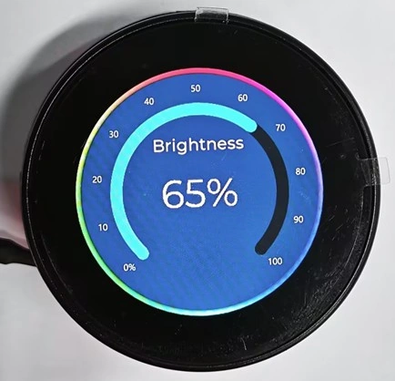
This lesson expands the circular display and knob-based dimming from the previous two lessons into a complete LVGL brightness gauge interface. ESPHome converts the official bj_light_1_360x360.png file into an RGB565 background image, then draws a title, a 0%-100% arc, and the brightness percentage over it. Each knob step adjusts the brightness by 5%, with the PWM backlight, arc position, and text updating simultaneously.
At the same time, the CST816 touch controller reads touch points over a 400 kHz I2C bus. The program mirrors and swaps the coordinate axes, then outputs both the processed and raw coordinates to the log. Through this lesson, learners will verify the complete signal chain for power, the SPI display, PSRAM image resources, LVGL widgets, knob input, PWM backlight, and I2C touch.
2. Learning Objectives
- Place the official 360×360 PNG asset in a location that ESPHome can parse and complete the image conversion.
- Explain the LVGL stacking order of the background image, arc, knob, and percentage label.
- Configure the CST816 I2C address, reset pin, interrupt pin, and coordinate transformation.
- Use the knob to control the PWM, arc, and brightness text simultaneously.
- Determine whether the touch direction is correct based on the processed coordinates, raw coordinates, and touch-point position on the screen.
3. Prerequisites
- A CrowPanel 1.46inch-HMI ESP32 Rotary Display with Lesson01 and Lesson02 completed.
- A USB cable that supports data transfer.
- ESPHome Device Builder 1.9.2.
- ESPHome 2026.7.4.
- The lesson code:
code/146-lvgl-interface.yaml. bj_light_1_360x360.pngfrom the official assets.- An internet connection for compiling Google Fonts and downloading assets.
Code download link: Official Elecrow Lesson_Code
Asset download link: Official Elecrow Material
Instructions for Adding Assets:
The following steps explain how to upload the assets you want to use on the ESPHome platform.
First, download the Samba Share tool. This tool makes it easier to upload the image assets you want to use.
First, install Samba.
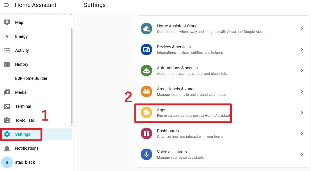
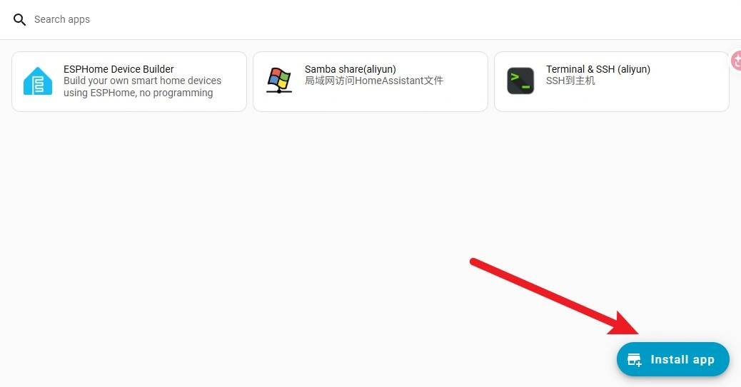
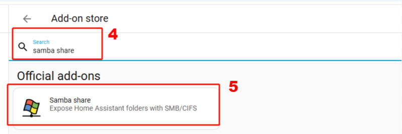
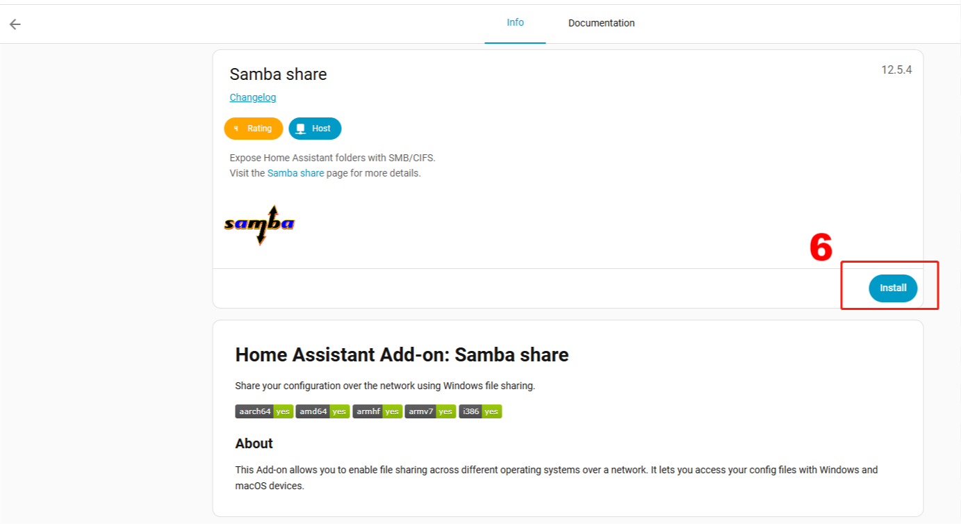
After the download is complete, configure your account on the tool's page. Enter the username and password used for your Home Assistant account.
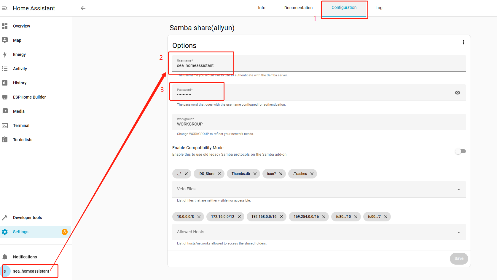
After completing the configuration, remember to click Save in the lower-right corner.
You can then open a file browser on your computer and enter \ followed by your Home Assistant IP address.
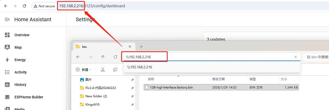
After opening it, you will see the file management interface for your current ESPHome installation.
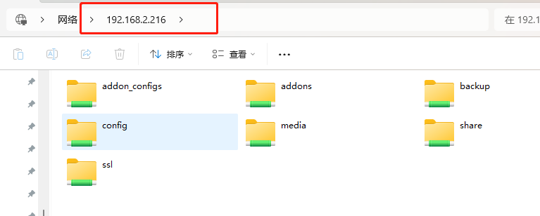
Open the config folder first, and then open the esphome folder.
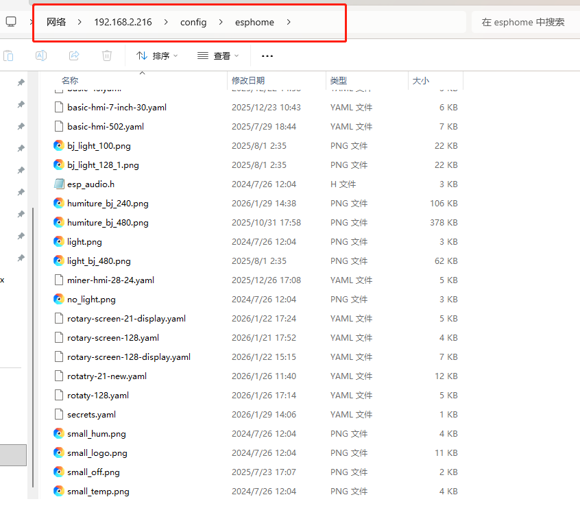
You can place the assets you need here. The asset names referenced in your code must match the names of the files placed here.
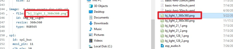
This allows the code to locate the assets during compilation and display them on the screen.
4. Software Setup Steps
Step01: Open ESPHome Device Builder 1.9.2 and confirm that its ESPHome Core version is 2026.7.4. If the versions do not match, upgrade or switch environments first to avoid component syntax differences. 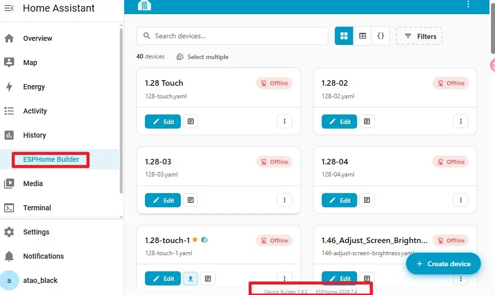
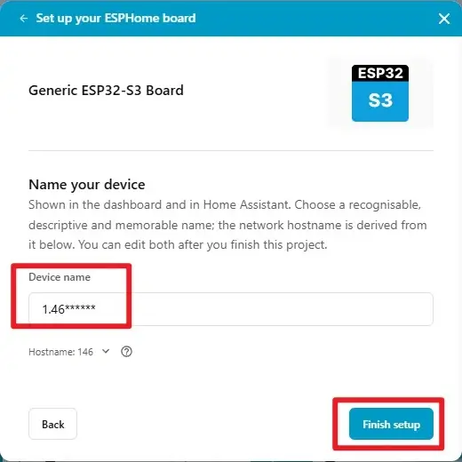
Step02: Create a new project, place 146-lvgl-interface.yaml in the ESPHome configuration directory, and open the corresponding configuration from the device list. The filename and esphome.name may differ, but device names on the same network must be unique.
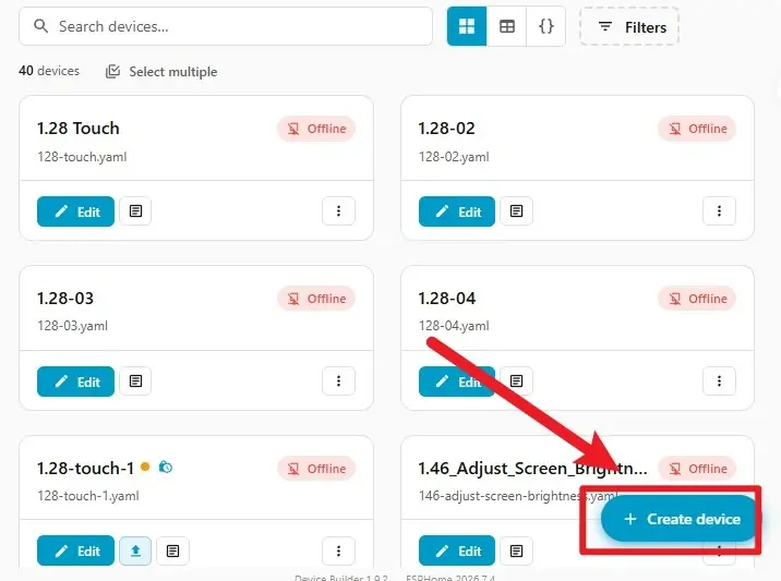
A. Click Create device to create a new project.
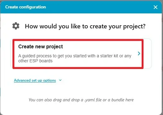
B. Select the ESP32-S3 microcontroller.
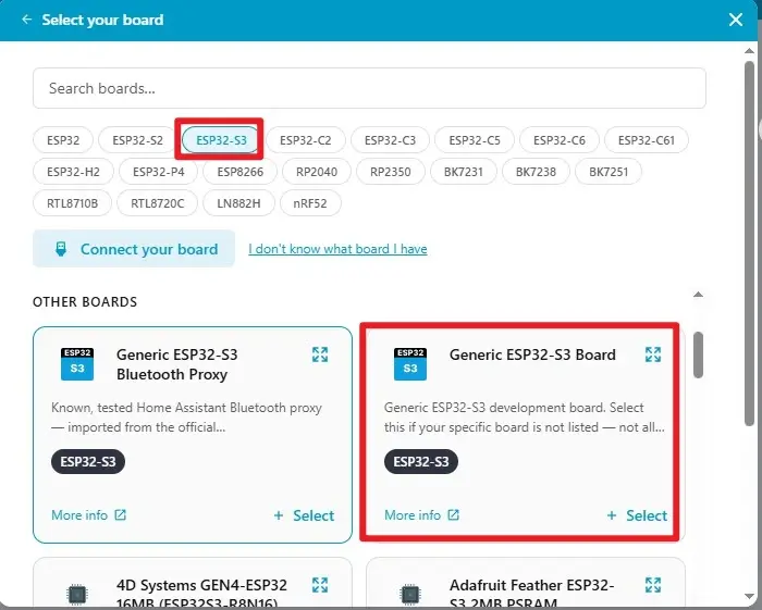
C. Name the project to finish creating it.
Step03: Copy the official code into the project. 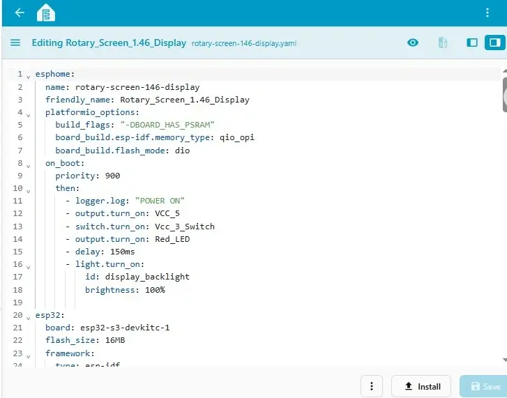
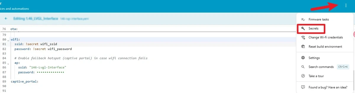
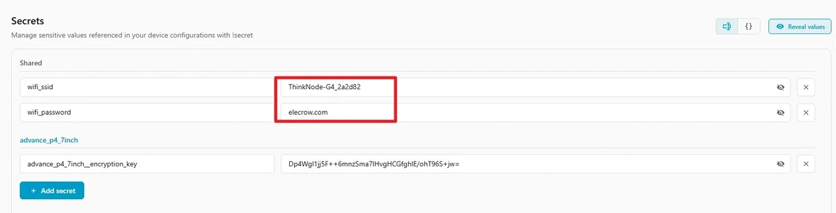
Step04: Update the Wi-Fi settings. Click the three dots in the upper-right corner, and then click secret. Enter your own Wi-Fi name and password.

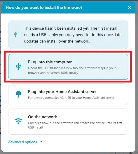
Step05: Click Install, select the USB installation method appropriate for the current environment, select the serial port corresponding to the CrowPanel, and complete compilation and flashing. After flashing is complete, open the log window. You should see the device startup messages and the POWER ON log entry.
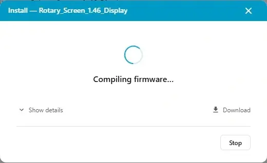
Step06: Wait for compilation to complete.
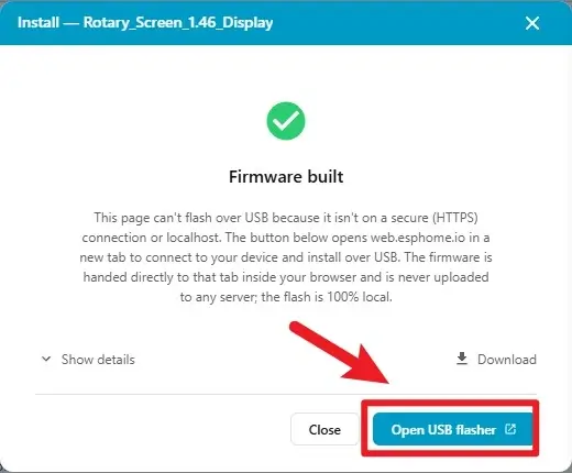
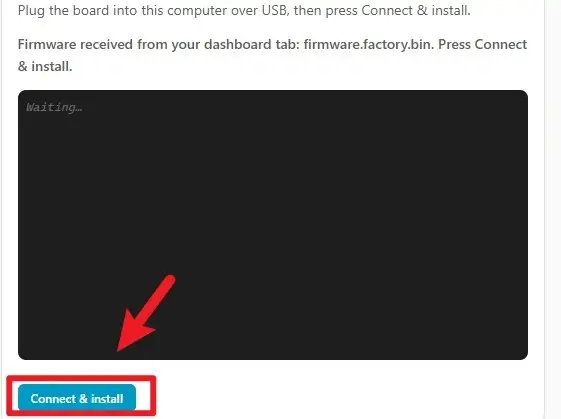
Step07: After compilation is complete, click flash to upload the firmware.
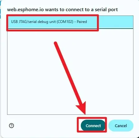
Step08: Select the connected serial port.
Step09: Click the corresponding serial port to connect to it (make sure the hardware is already connected).
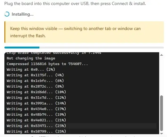
Step10: Wait for the download to complete.
5. Hardware Operation Steps
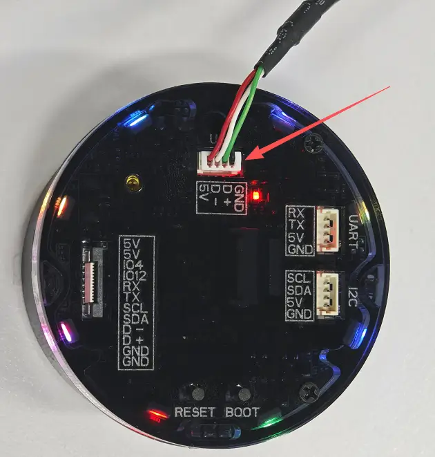
Step01: With the device powered off, check that the screen, knob enclosure, and USB port show no visible damage. Then use a data-capable USB cable to connect the CrowPanel to the computer.
Step02: Continuously alternate between adjusting the brightness with the knob and touching the screen. The interface should continue refreshing, touch logs should continue to be generated, and the device should not freeze or restart. Confirm that touch input does not unintentionally change the brightness value in this lesson, because the code only records touch coordinates.
6. Key Code Explanation
6.1 Image Asset Conversion
During compilation, ESPHome reads the PNG file and converts it into RGB565 pixel data suitable for the LCD. The file path is relative to the directory containing the YAML file, so a missing file will cause an error before compilation. The 360x360 dimensions match the screen size, avoiding runtime scaling. RGB565 uses 16 bits per pixel, providing a balance between color quality and memory usage. After changing the filename, you must also update file; otherwise, the firmware cannot be generated.
6.2 Using a PSRAM Buffer for a Large LVGL Interface
LVGL uses the circular display as its rendering target and allocates a relatively large portion of memory for the refresh buffer. A background image and a 360×360 interface require more memory than a text-only page, so this lesson relies on Octal PSRAM. A buffer that is too small may increase the number of partial refresh operations, while one that is too large may reduce the memory available to other components. If startup restarts or allocation failure messages occur, verify the PSRAM configuration and the actual hardware before increasing the percentage.
6.3 Widget Order from Background to Foreground
widgets:
  - image:
      id: img_bg
      src: img_bg_light
  - label:
      id: lbl_title
      text: "Brightness"
  - arc:
      id: arc_brightness
      min_value: 0
      max_value: 100
  - label:
      id: lbl_brightness
      text: "50%"
Widgets are stacked from bottom to top in the order in which they are defined: the background image is created first, followed by the title, arc, and percentage label over it. If the background image is placed last, it may cover the other widgets. The arc range matches the brightness percentage, allowing a single integer value to be used for the PWM, arc, and text. If the background appears correctly but the widgets are not visible, check the stacking order, colors, and opacity first.
6.4 Updating Three Outputs with the Knob
float level = id(brightness_value) / 100.0f;
id(backlight).set_level(level);

lv_arc_set_value(id(arc_brightness), id(brightness_value));
snprintf(buf, sizeof(buf), "%d%%", id(brightness_value));
lv_label_set_text(id(lbl_brightness), buf);
lv_refr_now(NULL);
A knob event first converts the integer percentage into a PWM value, then writes the same value to the arc and label. This ensures that all three outputs share the same state, preventing inconsistencies between the interface and the hardware. If lv_arc_set_value is removed, the backlight and text will still change, but the arc will remain at its previous position. If set_level is removed, the interface will change, but the actual backlight will not. These behaviors can be used to isolate UI and hardware output issues.
6.5 CST816 Bus and Coordinate Orientation
i2c:
  - id: i2c_touch
    sda: 6
    scl: 7
    scan: true
    frequency: 400kHz

touchscreen:
  platform: cst816
  interrupt_pin: 5
  reset_pin: 13
  address: 0x15
  transform:
    mirror_x: false
    mirror_y: true
    swap_xy: true
GPIO6 and GPIO7 form the touch I2C bus, GPIO5 receives the touch interrupt, and GPIO13 resets the controller. mirror_y and swap_xy transform the controller coordinates to match the current screen orientation. If touching the left side of the screen is recorded as touching the top, the axis swap or mirroring configuration does not match the display orientation. Before making changes, record the coordinates at all four edges and the center to avoid determining the orientation based on a single touch.
6.6 Touch Events Provide Diagnostic Output Only
on_touch:
  - logger.log:
      format: "Touch at (%d, %d)"
      args: [touch.x, touch.y]
  - lambda: |-
      ESP_LOGI("cal", "x=%d, y=%d, x_raw=%d, y_raw=%d",
        touch.x, touch.y, touch.x_raw, touch.y_raw);
Each touch first outputs the transformed coordinates, followed by a comparison of the processed and raw coordinates. This callback does not modify the arc or brightness, so it is expected that touching the screen does not change the brightness. If no log messages appear, check the I2C address and interrupt pin first. If raw data is available but the direction is incorrect, check transform instead of modifying the LVGL widgets first.
7. Feature or Asset Creation Process
This lesson uses the official prebuilt 360×360 PNG and does not require learners to redraw it. The asset integration process is as follows: download bj_light_1_360x360.png from the official Material repository, keep the filename unchanged, place it in the same directory as the YAML file, and allow ESPHome to convert it to RGB565 during compilation. In the code, img_bg_light is the compiled asset ID, while img_bg is the runtime LVGL image widget ID. They serve different purposes.
If you later replace the background with a custom image, keep it at 360×360 pixels and account for the fact that the corners are not visible on a circular screen. After replacing the file, run Validate and compile again to confirm that the image format, memory usage, and text contrast are correct.
8. Expected Results
After the device resets, power and the backlight turn on first, followed by the background image, title, brightness arc, and 50% percentage. The interface should fully cover the circular screen without obvious rectangular clipping, incorrect colors, or missing areas.
When the knob is rotated, the percentage changes in 5% increments, the indicated length of the brightness arc changes accordingly, and the actual backlight becomes brighter or dimmer with the value. After reaching 0% or 100%, continuing to rotate the knob keeps the value within the valid range.
When the screen is touched with a finger, the log window should immediately output the processed coordinates. The diagnostic log also displays x_raw and y_raw. The coordinates should change accordingly when different areas are touched, but the interface widgets and brightness in this lesson should not change in response to touch. During continuous touching and rotation, the device should not restart, freeze, or stop refreshing for an extended period.
Initial draft acceptance note: Pending verification on actual CrowPanel hardware for background image colors, knob direction, CST816 coordinate orientation, and continuous interaction stability.
9. Code Downloads
- Official code: Elecrow ESPHome Lesson_Code
- Official assets: Elecrow ESPHome Material