Lesson01_ESP32-P4_AI_Voice_Chat: CrowPanel 7/9/10.1-inch AI Voice Chat Robot
1. Course Introduction
This lesson uses ESP-IDF 5.4.2 to drive the CrowPanel Advanced 7 / 9 / 10.1-inch ESP32-P4 HMI. The project uses the ESP32-P4 to handle MIPI DSI display, PDM microphone capture, I2S speaker output, button interaction, and MIPI CSI camera image processing, and establishes Wi-Fi connectivity through the ESP32-C6 coprocessor, ultimately forming a complete pipeline of "voice input—network AI service—voice and interface output."
After the program is flashed and reset, the system sequentially initializes the amplifier control, the EK79007 display, the function buttons, the camera power, and the camera data link; it then waits for ESP32-C6 communication to become ready and connects to Wi-Fi. Users can switch the conversation state via the function button, speak through the microphone, and have replies played back through the speaker; when visual functions are needed, the camera captures 1024 × 600 RGB565 images and can compress them into JPEG for upload and analysis.
2. Learning Objectives
- Be able to explain the division of responsibilities among ESP32-P4, ESP32-C6, MIPI DSI, MIPI CSI, PDM, and I2S in this project.
- Be able to identify the key configurations for 1024 × 600 display, 16 kHz audio, buttons, backlight, touch, and camera.
- Be able to complete the checks for the ESP32-P4 target, 16 MB Flash, Hex PSRAM, and project partition configuration.
- Be able to explain the initialization sequence within the board constructor and the corresponding screen, sound, network, and camera behaviors.
- Be able to locate display, audio, camera, or network link faults based on compilation logs, serial logs, and device behavior.
3. Prerequisites
3.1 Hardware
- One CrowPanel Advanced 7 / 9 / 10.1-inch ESP32-P4 HMI AI development board.
- One USB data cable that supports data transfer; do not use a power-only cable.
- On-board or companion PDM microphone, speaker, and MIPI CSI camera.
- Stable USB power supply; power must be disconnected before connecting or disconnecting the camera flex cable.
- An available 2.4 GHz Wi-Fi network.
3.2 Software and Project
- A Windows PC, VS Code, and the Espressif IDF extension.
- ESP-IDF v5.4.2; the project README requires 5.4 or above, and this lesson uses the actually verified environment 5.4.2 as the standard.
- Fully preserve the project's
main,managed_components,partitions,dependencies.lock,sdkconfig, andsdkconfig.defaults*. - Target chip:
esp32p4. - Flash: 16 MB; custom partition table:
partitions/v2/16m.csv. - PSRAM: Hex mode, 200 MHz; configured in the project via
sdkconfig.
Code download link: CrowPanel-Advanced-7inch-ESP32-P4-HMI-AI-Display-1024x600-IPS-Touch-Screen
4. Software Operation Steps
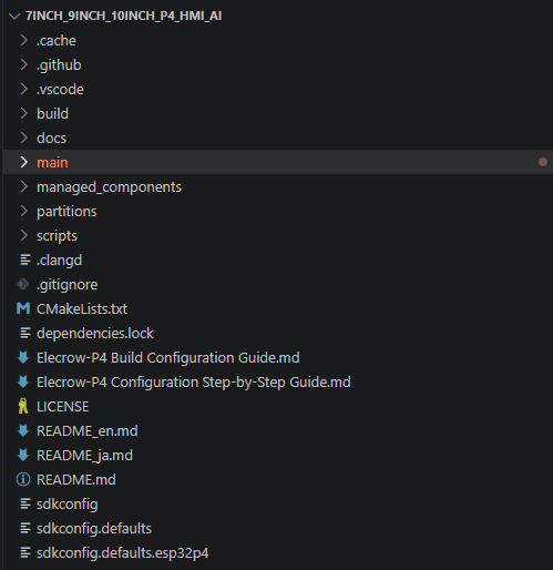
Open the ESP-IDF extension panel in VS Code, click Open ESP-IDF Project, and select the 7inch_9inch_10inch_P4_HMI_AI folder. After the project opens, confirm that the root directory in the Explorer contains CMakeLists.txt, main, managed_components, partitions, and sdkconfig.
Do not open only the main subdirectory; otherwise ESP-IDF will not be able to load the complete component dependencies and project configuration.
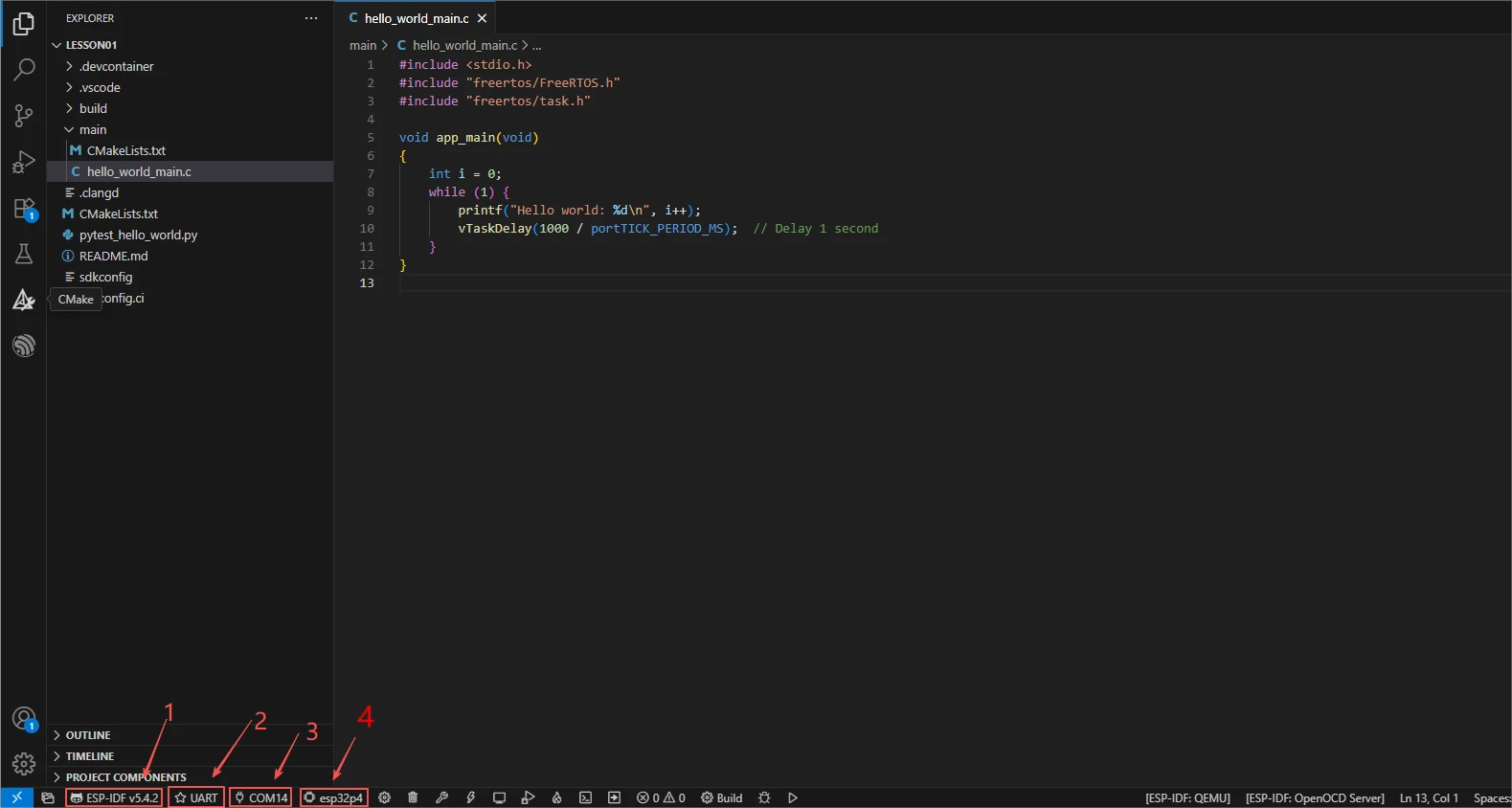
First, select the code runtime environment ESP-IDF v5.4.2 in the bottom status bar of VS Code, set the flashing method to UART, and then select the serial port that actually corresponds to the development board. Then click Set Espressif Device Target and select esp32p4. After configuration, the status bar should simultaneously display ESP-IDF v5.4.2, UART, the corresponding COM port, and ESP32-P4.
Since the SDK configuration has already been set up for you, no further configuration is needed—you can use it directly.
However, during use, you need to switch the network in this project to your own network environment.
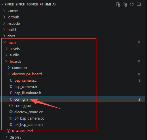
Open main->boards->elecrow-p4-board->config.h
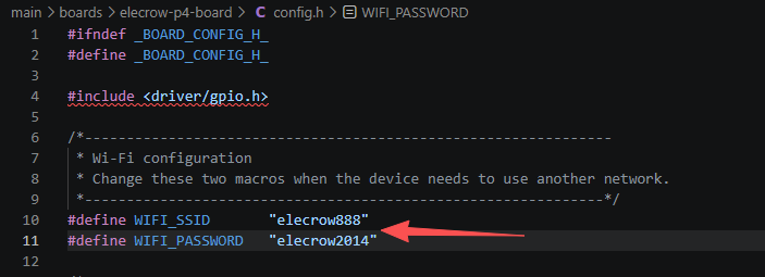
Modify the Wi-Fi name and password inside to your own.
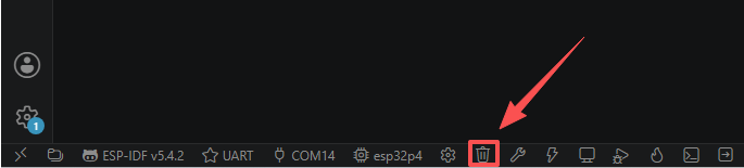
After the first build, or after switching project configuration or modifying SDK parameters, click Full Clean in the status bar to clear the old build cache. Wait for the cleanup to finish before compiling, to avoid the old CMake cache, target chip, or Hosted parameters affecting this build result.
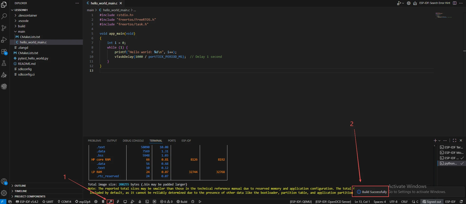
Click Build to compile the project. Under normal circumstances, dependency resolution, CMake configuration, and Ninja compilation will complete in sequence, finally outputting Project build complete. If esp_hosted reports Unknown Slave Target, return to steps 4 and 5 to check the ESP32-C6 slave target and the Hosted/SDIO configuration; if it prompts that the ESP-IDF environment variable is missing, re-export the environment instead of directly modifying the display, audio, or camera code.
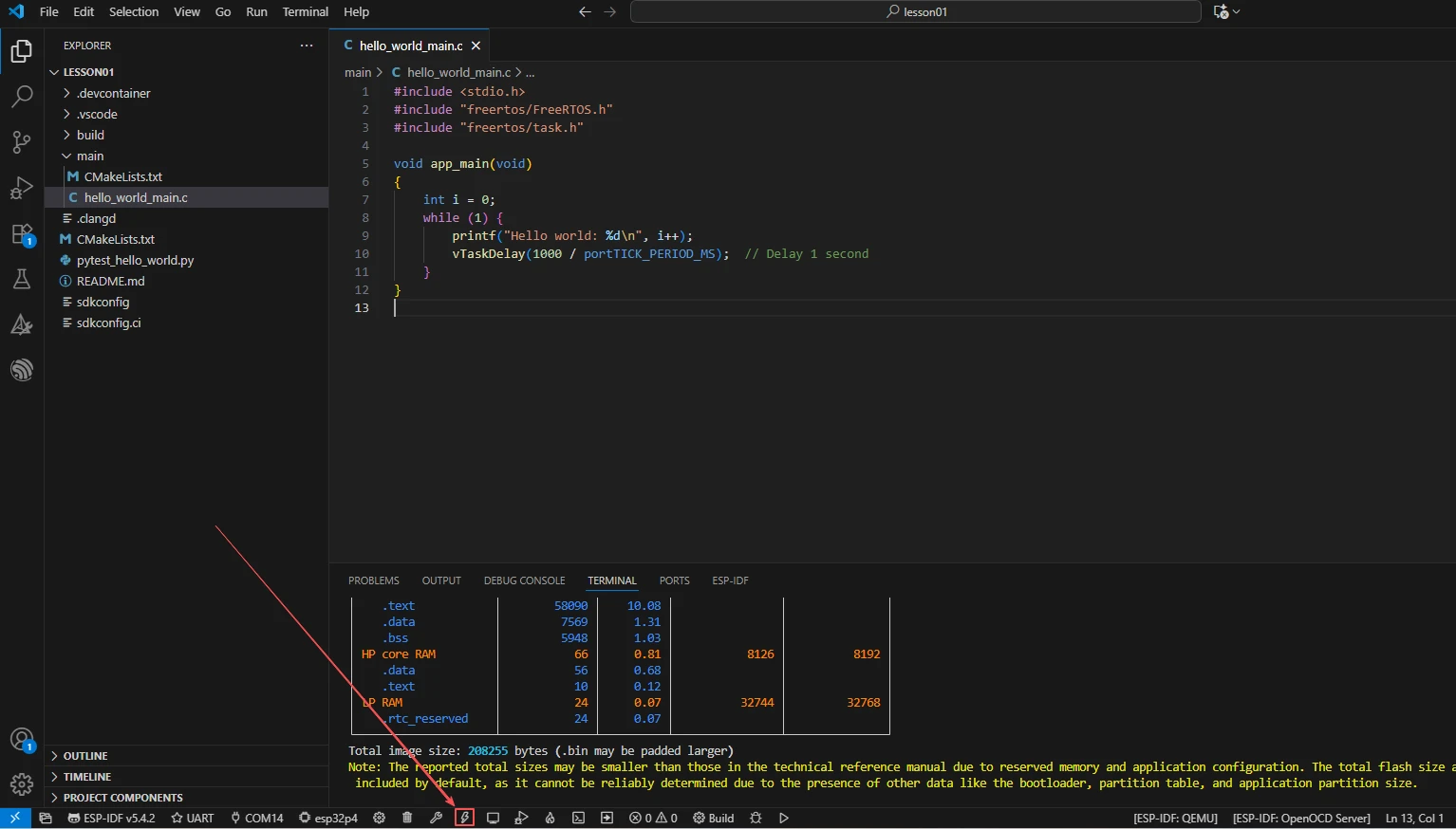
Connect the development board using a USB cable that supports data transfer, click Select Port to Use to choose the correct serial port, then click Flash to flash the firmware. Do not unplug the USB cable or cut power during flashing; after completion, the development board should reset automatically.
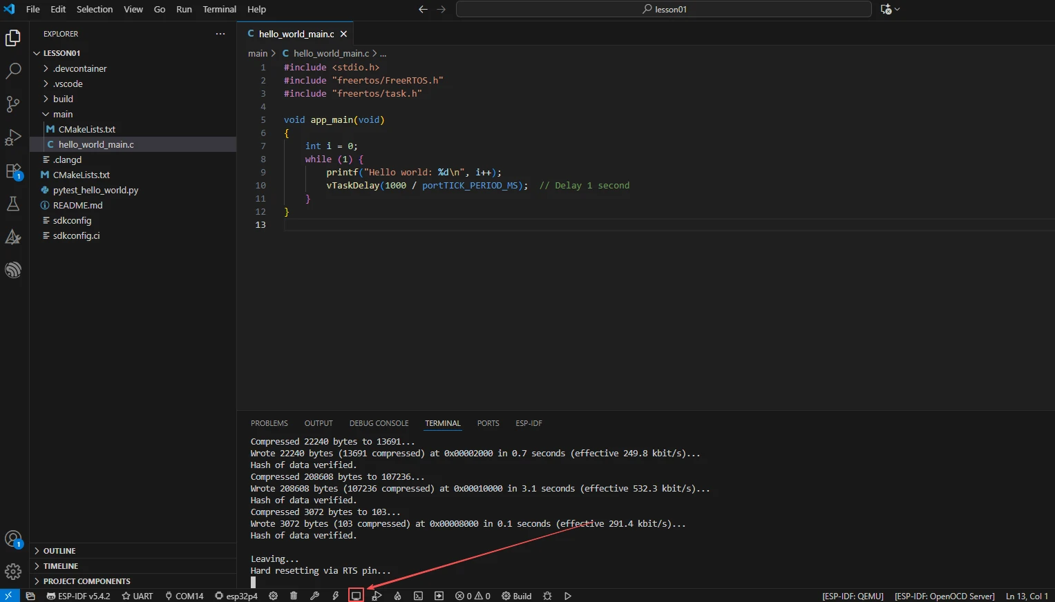
Click Monitor to open the serial monitor. After the device resets, you should sequentially see logs for Initializing Elecrow P4 Board..., LCD, buttons, camera power, camera initialization, and network startup. Use Ctrl + ] to exit the monitor. Wi-Fi passwords, access tokens, or device unique identifiers must not appear in course screenshots or public logs.
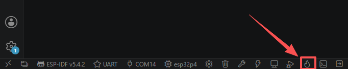
After the project configuration, serial port, and code are all confirmed correct, you can click the one-click operation button in the ESP-IDF status bar to sequentially complete compilation, flashing, and opening the serial monitor. When problems occur, you should still execute steps 7–10 separately, in order to determine whether the fault occurred during the cleanup, compilation, flashing, or running phase.
5. Hardware Operation Steps
Before connecting the USB power, confirm that the development board is powered off.
Check that the MIPI CSI camera flex cable is oriented correctly, that the gold contacts are fully inserted into the connector and the latch is firmly locked, and confirm that the LCD flex cable, microphone, speaker, and Wi-Fi antenna (if required by the current model) are securely connected. Hot-plugging the camera flex cable is prohibited.
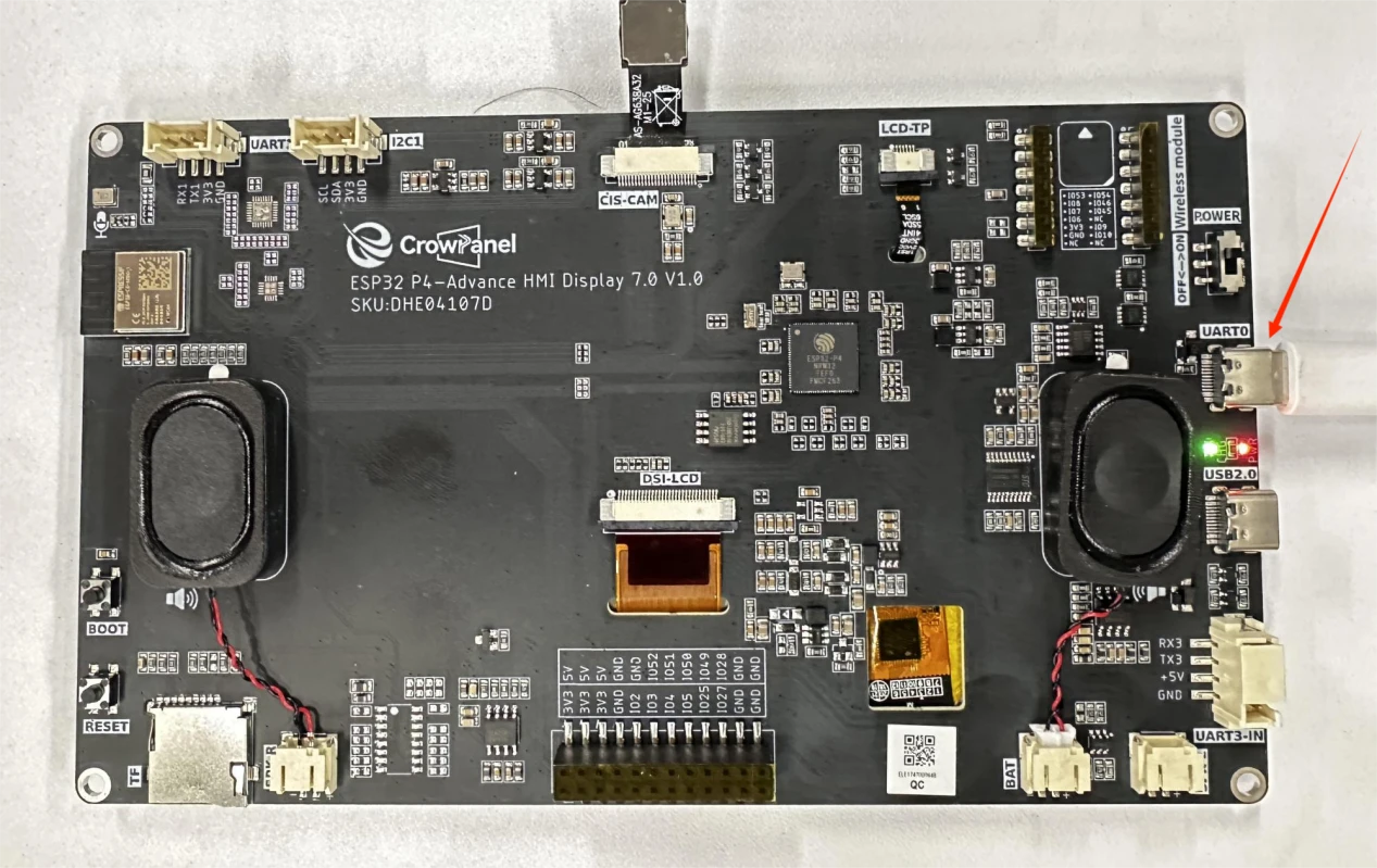
Connect the ESP32-P4 development board to the computer using a USB cable that supports data transfer, and confirm that the power indicator lights up and that the serial port can be recognized by VS Code.
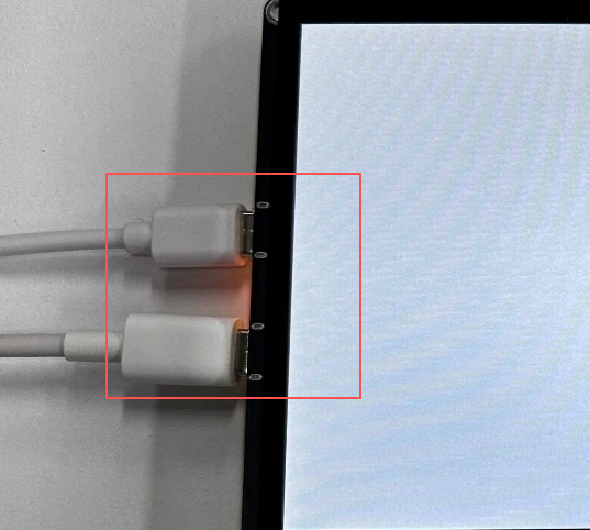
This project requires a lot of hardware, so you must provide the ESP32-P4 development board with sufficient power.
After the firmware is flashed and automatically resets, observe whether the display backlight lights up and whether the 1024 × 600 interface displays completely. A normal screen should not show persistent black screen, color distortion, obvious misalignment, or partial missing content. If there is only backlight but no image, you should first check the MIPI DSI PHY power, the two-lane configuration, and the LCD (EK79007) initialized: 1024x600 log.
After the device resets, wait about 2 seconds for the ESP32-P4 and the on-board ESP32-C6 to establish communication via SDIO. Open the serial monitor; the program should output the number of saved SSIDs and begin connecting to Wi-Fi; confirm that there are no persistent Hosted/SDIO initialization failures in the log. Network connection time is affected by the router and signal strength.
After the network connects successfully, briefly press the GPIO35 function button to switch the chat state, and speak a clear, short sentence into the PDM microphone. The interface should display changes in recording, processing, or reply status; after the AI service responds, the speaker should play the voice reply. During testing, keep an appropriate distance between the microphone and the speaker to avoid howling/feedback that affects voice recognition.
After connecting to Wi-Fi, it will connect to the xiaozhi platform.
For connection steps, please refer to: CrowPanel-Advanced-7inch-ESP32-P4-HMI-AI-Display-1024x600-IPS-Touch-Screen/example/V1.0/idf-code/7_9_10.1_P4_HMI_AI at master · Elecrow-RD/CrowPanel-Advanced-7inch-ESP32-P4-HMI-AI-Display-1024x600-IPS-Touch-Screen
After completing the steps above, you will be able to have conversations with xiaozhi.
6. Key Code Explanation
6.1 Board Function Parameters: Sound, Display, and Peripheral Pins
File: main/boards/elecrow-p4-board/config.h
#define AUDIO_INPUT_SAMPLE_RATE  16000
#define AUDIO_OUTPUT_SAMPLE_RATE 16000
#define AUDIO_I2S_GPIO_WS   GPIO_NUM_21
#define AUDIO_I2S_GPIO_BCLK GPIO_NUM_22
#define AUDIO_I2S_GPIO_DOUT GPIO_NUM_23
#define AUDIO_PDM_MIC_CLK   GPIO_NUM_24
#define AUDIO_PDM_MIC_DIN   GPIO_NUM_26

#define DISPLAY_WIDTH  1024
#define DISPLAY_HEIGHT 600
#define LCD_MIPI_DSI_LANE_NUM 2
#define DISPLAY_BACKLIGHT_PIN GPIO_NUM_31
These macros are read when the board object is constructed and when the audio service starts. Both input and output run at 16 kHz, keeping a unified sample rate for the voice pipeline; the speaker uses the standard I2S WS, BCLK, and DOUT, while the microphone uses independent PDM clock and data input. If the two sets of pins are confused, the program may start normally but have no recording or no sound.
The display resolution must simultaneously match the panel, the MIPI DPI configuration, and the LVGL display object. Incorrect width or height will cause interface cropping, misalignment, or out-of-bounds refresh; when the DSI lane count does not match the physical hardware, the screen may show no image at all. The backlight GPIO only controls "whether it is visible"; a black screen does not necessarily mean MIPI initialization failed—you should first distinguish between the backlight and the image data link.
6.2 Board Initialization Sequence Determines Power-on Behavior
File: main/boards/elecrow-p4-board/elecrow_board.cc
InitializeAudioCtrl();
InitializeLCD();
InitializeButtons();
GetBacklight()->RestoreBrightness();
bsp_enable_camera_power();
InitializeCamera();
This code executes when ElecrowP4Board is constructed. It first enables the amplifier control, then establishes the display link; after LCD initialization completes, the backlight is restored, so the normal behavior is that the display object is prepared first, and then the user sees the backlight and interface. The camera must first be powered with 3.3 V from LDO4, then accessed via SCCB/CSI; if the order is swapped, sensor detection may fail.
If the screen does not light up, first check whether LCD (EK79007) initialized appears on the serial port, then check the GPIO31 backlight. If the log stalls at camera initialization, check the flex cable, 3.3 V power supply, and SCCB pins, rather than directly suspecting the AI service.
6.3 MIPI DSI Display Link
esp_lcd_dsi_bus_config_t bus_config = {
    .bus_id = 0,
    .num_data_lanes = LCD_MIPI_DSI_LANE_NUM,
    .phy_clk_src = MIPI_DSI_PHY_CLK_SRC_DEFAULT,
    .lane_bit_rate_mbps = 1000,
};

ESP_ERROR_CHECK(esp_lcd_new_panel_ek79007(panel_io, &panel_config, &panel));
ESP_ERROR_CHECK(esp_lcd_panel_reset(panel));
ESP_ERROR_CHECK(esp_lcd_panel_init(panel));
The DSI PHY is first powered by a 2.5 V LDO, then a two-lane, 1000 Mbps DSI bus is created. After the EK79007 driver object completes reset and initialization, MipiLcdDisplay can send the LVGL refresh content to the panel. When the PHY voltage, lane count, or driver chip does not match, the backlight may still light up but there is no correct picture; this is the key distinction for troubleshooting a "lit black screen."
6.4 Function Button and Chat State
boot_button_.OnClick([this]() {
    auto& app = Application::GetInstance();
    if (app.GetDeviceState() == kDeviceStateStarting &&
        !WifiStation::GetInstance().IsConnected()) {
        ResetWifiConfiguration();
    }
    app.ToggleChatState();
});
The callback executes when a button click event occurs on GPIO35. When the device is still in the starting state and not connected to the network, the button first triggers a Wi-Fi configuration reset; afterward, regardless of the current state, it calls ToggleChatState() to switch the chat state. Therefore, the same button serves both network recovery and chat control purposes.
Do not conduct unverified experiments by changing the active level, otherwise it may cause a continuously pressed state or abnormal boot mode. If the button does not respond, check GPIO35, the button callback registration log, and the application state machine in sequence, rather than checking only the interface.
6.5 PDM Microphone and I2S Speaker Adaptation
static NoAudioCodecSimplexPdm audio_codec(
    AUDIO_INPUT_SAMPLE_RATE,
    AUDIO_OUTPUT_SAMPLE_RATE,
    AUDIO_I2S_GPIO_BCLK,
    AUDIO_I2S_GPIO_WS,
    AUDIO_I2S_GPIO_DOUT,
    AUDIO_PDM_MIC_CLK,
    AUDIO_PDM_MIC_DIN);
This board has no external audio codec chip, so NoAudioCodecSimplexPdm is used: the speaker uses standard simplex I2S output, and the microphone uses PDM input. This static object is created the first time the audio service calls GetAudioCodec() and is reused throughout the entire program lifecycle.
If voice can be recognized but not played back, first check GPIO21/22/23 and the GPIO30 amplifier enable; if it can be played but not recognized, first check GPIO24/26 and the microphone orientation. The two links are independent; "the speaker has sound" cannot prove the microphone is normal.
6.6 Camera Capture: Sensor → CSI → ISP → PSRAM
File: bsp_camera.c
camera_buffer_size = 1024 * 600 * ((BITS_PER_PIXEL + 7) / 8);
camera_buffer = heap_caps_aligned_calloc(
    cache_line_size, 1, camera_buffer_size,
    MALLOC_CAP_SPIRAM | MALLOC_CAP_8BIT);

err = camera_sensor_init();
err = camera_csi_init();
err = isp_init();
err = esp_cam_ctlr_start(cam_handle);
RGB565 occupies 2 bytes per pixel, so one frame requires about 1.17 MiB; therefore the frame buffer must be placed in PSRAM and aligned to the cache line. The sensor output mode is MIPI_2lane_24Minput_RAW8_1024x600_30fps; CSI receives RAW8, and the ISP then converts it to RGB565. When PSRAM is not enabled or fragmentation is severe, the first symptom to appear is usually buffer allocation failure, not a network error.
The resolution, pixel format, and buffer size must be synchronized. Modifying only one of them will cause color anomalies, screen tearing, out-of-bounds access, or reboot.
6.7 Image Preview and Memory Ownership
File: p4_bsp_camera.cc
esp_err_t err = camera_refresh();
auto img_dsc = (lv_img_dsc_t*)heap_caps_calloc(
    1, sizeof(lv_img_dsc_t), MALLOC_CAP_8BIT);
img_dsc->data = (uint8_t*)heap_caps_malloc(
    img_dsc->data_size, MALLOC_CAP_SPIRAM);
memcpy((void*)img_dsc->data, my_trans.buffer, img_dsc->data_size);
display->SetPreviewImage(img_dsc);
Capture() first waits for a new frame, then creates an independent LVGL image descriptor and copies the frame into a new PSRAM region. The purpose of copying is not to improve speed, but to prevent CSI from overwriting the shared capture buffer while the display is still reading the old image. If the descriptor or image memory allocation fails, the function returns false, and the interface will not receive a new preview image.
6.8 JPEG Stream Encoding and Visual Interpretation Request
QueueHandle_t jpeg_queue = xQueueCreate(40, sizeof(JpegChunk));
encoder_thread_ = std::thread([this, jpeg_queue, &fb]() {
    frame2jpg_cb(&fb, 80, /* chunk callback */, jpeg_queue);
});

http->SetHeader("Content-Type", "multipart/form-data; boundary=" + boundary);
http->SetHeader("Transfer-Encoding", "chunked");
Explain() does not first allocate one complete large JPEG buffer; instead, it lets the encoding thread generate data in chunks, which are handed to the HTTP writer through a FreeRTOS queue. This reduces the pressure of large contiguous memory. The JPEG quality parameter is 80, a compromise between clarity and upload size; when the network disconnects, the code reclaims chunks in the queue that have not yet been sent, avoiding obvious memory leaks.
If the interface address or token is empty, the function throws an exception; if the HTTP status code is not 200, it is also treated as a failure. Troubleshooting should distinguish among the four phases: "camera has no frame," "JPEG encoding failed," "network connection failed," and "server rejected the request."
6.9 ESP32-C6 Network Startup and Configuration Risks
vTaskDelay(pdMS_TO_TICKS(2000));
auto& ssid_manager = SsidManager::GetInstance();
auto ssid_list = ssid_manager.GetSsidList();
WifiBoard::StartNetwork();
The main controller fixedly waits 2 seconds before starting the network, leaving initialization time for the ESP32-C6 and SDIO communication. It then reads the saved networks, and finally calls the parent class to complete the normal connection flow. If esp_hosted's Unknown Slave Target appears during the build phase, it means the Wi-Fi slave target configuration has not yet been satisfied; the problem occurs at the network component configuration layer and cannot be solved by modifying LCD or camera code.
7. Experimental Observations
- After the device resets, the serial port shows
Initializing Elecrow P4 Board.... - After MIPI DSI initialization completes,
LCD (EK79007) initialized: 1024x600appears, the backlight lights up, and the complete interface is displayed. - The serial port shows
Buttons initialized; after briefly pressing the function button, the chat state changes. - After camera power is successfully enabled,
Camera power enabled (LDO4: 3300mV)appears; when the camera succeeds,P4 BSP Camera initialized successfullyappears. - When the network starts, it first waits about 2 seconds, then outputs the number of saved SSIDs and attempts to connect.
- When the network and AI service are normal, after speaking into the microphone, the device enters the processing state and finally plays the reply from the speaker.