Lesson 02: UART1 Interface LED Control
Applicable development board: CrowPanel Advanced 7 / 9 / 10.1inch ESP32-P4 HMI AI Display
Model compatibility: The 7-inch, 9-inch, and 10.1-inch models are fully interchangeable in terms of hardware interfaces and software code; only their physical dimensions differ. Please select a model based on your actual display size and use case. No code modification is required for this lesson.
1. Course Introduction
Use the LED on the UART1 interface as a regular GPIO, and use high/low voltage levels to create a cycle of 1 second on and 1 second off.
2. Learning Objectives
After completing this lesson, you should be able to:
- Understand GPIO output mode and the current-sinking connection of an LED.
- Use
pinMode(),digitalWrite(), and blockingdelay(). - Locate the UART1 LED based on the pin macros in
config.h.
3. What You Need
- Prepare the CrowPanel Advanced 7 / 9 / 10.1inch ESP32-P4 HMI AI Display board and a USB-C data cable according to the quantity required for this lesson.
- The UART1 interface on the board is labeled
UART, and the LED uses GPIO48. - The
config.hand.inofiles in the project must be placed in the same project directory.
Code reference: https://github.com/Elecrow-RD/CrowPanel-Advanced-7inch-ESP32-P4-HMI-AI-Display-1024x600-IPS-Touch-Screen/tree/master/example
4. Software Operation Steps
Double-click to open the Lesson 2 code. (.ino file)

Configure the options as described below.
- Board:
ESP32P4 Dev Module - Core Debug Level:
Info - Flash Frequency / Mode / Size:
80MHz/QIO/16MB (128Mb) - Partition Scheme:
16M Flash (3MB APP/9.9MB FATFS) - PSRAM:
Enabled - USB Mode:
Hardware CDC and JTAG - Port: After connecting the USB data cable to the board's UART0, select the newly appeared COM port under "Tools → Port".

5. Hardware Operation Steps
5.1 Identify Hardware and Safety Boundaries
Now that the code is ready, we need to flash the ESP32-P4 to see the results in action.
First, connect the Advance-P4 device to your computer host via a USB cable.

The UART1 interface is labeled UART, and the LED uses GPIO48.


5.2 Open the Project and Verify the Pins
Open Lesson02-Turn_on_the_LED.ino and confirm that config.h exists in the same directory. This file centrally stores the hardware constants, making it easy to change pins without modifying the control logic.


5.3 Compile, Upload, and Observe
Before uploading the code, first select the upload configuration as described in "4. Software Operation Steps."
Connect to UART0 and compile and upload using the standard configuration. Keep the board powered on and observe the on/off cycle of the UART1 LED.

6. Key Code Explanation
6.1 GPIO Output and Timing Control
#include "config.h"

void setup() {
  pinMode(PIN_LED, OUTPUT);
}

void loop() {
  digitalWrite(PIN_LED, HIGH);
  delay(1000);
  digitalWrite(PIN_LED, LOW);
  delay(1000);
}
pinMode(PIN_LED, OUTPUT) configures GPIO48 as an output;
digitalWrite() establishes the two voltage states of on and off;
delay(1000) is a blocking delay, suitable for this lesson's demonstration but not for complex concurrent control.
7. Experimental Observations
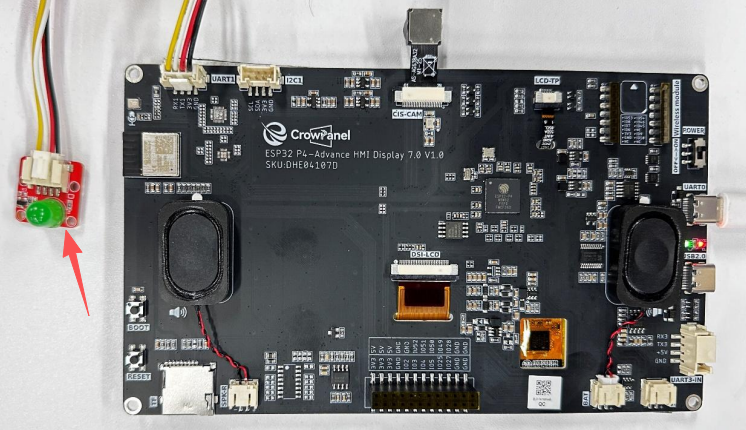
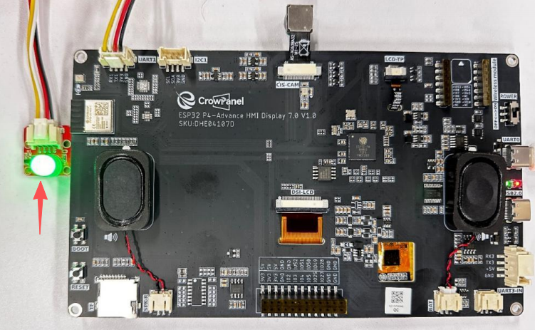
- The LED should stay on for 1 second, off for 1 second, and repeat continuously in a loop.
8. Common Issues and Troubleshooting
- If the on/off logic is reversed, follow the active-level macro defined by the board-level circuitry.
- If the LED does not light up at all, check GPIO48, the interface orientation, and the power supply. Do not arbitrarily switch to unknown pins.