Lesson 03: UART3-IN External Power Supply Interface
Compatible boards: CrowPanel Advanced 7 / 9 / 10.1inch ESP32-P4 HMI AI Display Development Board
Model compatibility: The 7-inch, 9-inch, and 10.1-inch models are fully interchangeable in terms of hardware interfaces and software code; only their physical dimensions differ. Select the model based on your actual display size and use case. This lesson requires no code modifications.
1. Course Introduction
This lesson does not involve writing any new program. Instead, building on the LED program from the previous lesson, it introduces the power supply, serial communication, and programming boundaries of the UART3-IN interface.
2. Learning Objectives
Upon completing this lesson, you should be able to:
- Distinguish the different purposes of UART0, UART3-IN, and USB 2.0.
- Correctly understand the 5V, GND, RX3, and TX3 pins of UART3-IN.
- Safely complete 5V external power wiring with the power turned off.
3. Prerequisites
- Prepare the CrowPanel Advanced 7 / 9 / 10.1inch ESP32-P4 HMI AI Display Development Board and a data-capable USB-C cable in the quantity required for this lesson.
- This lesson adds no new code; verification can reuse the LED program from Lesson 02.
- Prepare an adjustable 5V power supply and two Dupont wires.
Code reference: This lesson contains no code and is purely a theoretical explanation.
4. Software Operation Steps
No code and no software operation.
5. Hardware Operation Steps
5.1 Understanding Interface Responsibilities
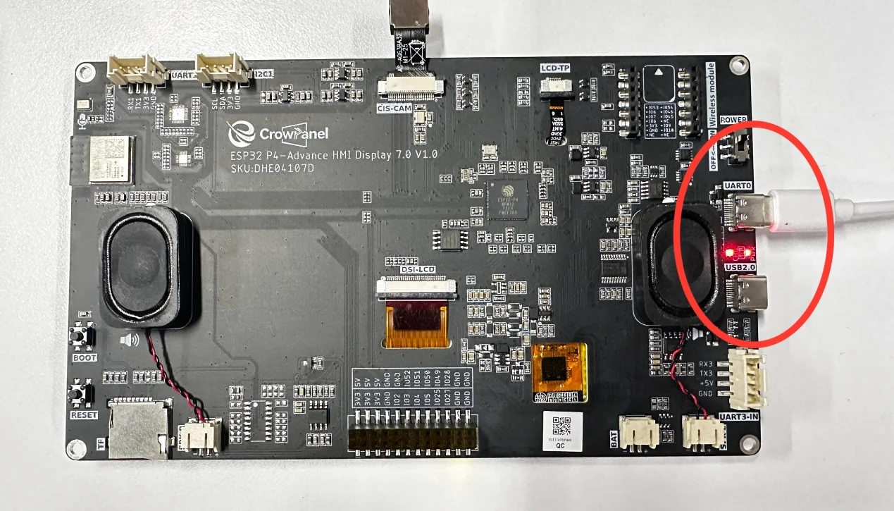
UART0 connects to the programming and debugging link; it can supply power, upload programs, and display logs.
At this point, you can see the UART3-IN and UART0 interfaces. In the previous lesson, when we uploaded the code, we learned that the UART0 pin is used for uploading programs. You can also see that after connecting the UART0 interface, the power indicator next to it lights up, indicating that it can still supply power.
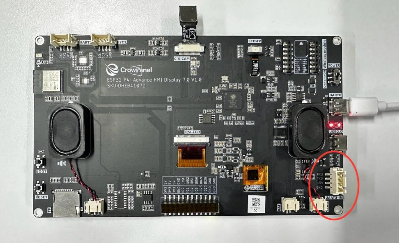
UART3-IN does not have the same programming chip; it is primarily used for external 5V input and can also serve as a general-purpose UART3 communication interface. It cannot replace UART0 for uploading programs.
5.2 External 5V Power Supply
Disconnect any other power connections and turn off the power output. Set the power supply to 5V with a current limit of 2A. Connect the positive terminal to the 5V/VCC pin of UART3-IN and the negative terminal to GND. Verify the polarity before turning on the output.
Now let's return to the UART3-IN interface. This interface is similar in function to the UART0 interface we just discussed. It can supply power, but it cannot upload code.
The UART0 interface is connected to a serial programming chip, which makes uploading code relatively convenient.
However, the UART3-IN interface does not have a serial programming chip. It can only be used for power supply and serial communication.
Therefore, we will now explain how the UART3-IN interface can be used to supply power. You need to prepare a power supply along with two Dupont wires. One wire connects the VCC pin of UART3-IN to the positive terminal of the power supply, and the other wire connects the GND pin of UART3-IN to the negative terminal of the power supply.
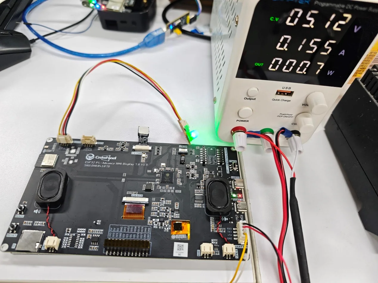
Note: The voltage and current used here are provided by a programmable power supply. You only need to ensure that the externally supplied voltage is 5V and the current is 2A, then connect them to the corresponding VCC and GND pins on UART3-IN (connect the positive terminal to VCC and the negative terminal to GND).
Make sure your wiring is correct, then turn on the power switch to supply power.
At this point, you will be able to see the LED that we turned on in the previous lesson. It is also blinking now, indicating that the power supply has been successful.
Of course, in addition to serving as a power input interface, UART3-IN can also be used as a normal serial port. Note, however, that when connecting to UART3-IN, since UART3-IN cannot supply power externally, the device connected to UART3-IN must be able to supply its own power.
6. Key Code Explanation
This lesson adds no new code. Verification can reuse the LED program already uploaded in the previous lesson, but this does not change the power supply and serial port functions of UART3-IN.
7. Experimental Observations
- When powered solely through UART3-IN, the power indicator lights up and the LED program uploaded in the previous lesson continues to run.
- You can explain why UART0 can upload programs while UART3-IN cannot, and can draw the wiring with crossed TX/RX connections and a shared GND.