Lesson 04: UART1 Serial Communication and AT Commands
Applicable Development Board: CrowPanel Advanced 7 / 9 / 10.1inch ESP32-P4 HMI AI Display Development Board
Model Compatibility: The 7-inch, 9-inch, and 10.1-inch models are fully interchangeable in terms of hardware interfaces and software code; only their physical dimensions differ. Select a model based on your actual display size and use case; no code modifications are required for this lesson.
1. Course Introduction
Connect the ESP8266/Crowtail Serial Wi-Fi module via UART1 to send AT commands, read responses, and establish a Wi-Fi/TCP service.
2. Learning Objectives
Upon completing this lesson, you should be able to:
- Correctly cross-connect the TX/RX lines between UART1 and the Wi-Fi module.
- Understand timeout-based reading, response buffers, and
OKdetermination. - Follow the task flow of "initialization → reset → connection → TCP service startup."
3. What You Need to Prepare
-
Prepare the CrowPanel Advanced 7 / 9 / 10.1inch ESP32-P4 HMI AI Display Development Board and a data-capable USB-C cable in the quantities required for this lesson.
-
Peripheral: ESP8266/Crowtail Serial Wi-Fi module.
This lesson focuses on how to use the serial (UART) component and how to configure and program the serial port in code. This course uses a serial Wi-Fi module as an example to demonstrate the basic development workflow of serial communication. If you are using a different serial module, you can also refer to the programming approach in this lesson and write the corresponding code based on the module's communication protocol and functions to achieve the desired functionality.
- The Wi-Fi module must use the 115200, 8N1 parameters consistent with the code; replace the example SSID/password with your own configuration.
Code Reference: https://github.com/Elecrow-RD/CrowPanel-Advanced-7inch-ESP32-P4-HMI-AI-Display-1024x600-IPS-Touch-Screen/tree/master/example
4. Software Operation Steps
Double-click to open the Lesson 04 code. (.ino file)

Configure the options below accordingly.
- Board:
ESP32P4 Dev Module - Core Debug Level:
Info - Flash Frequency / Mode / Size:
80MHz/QIO/16MB (128Mb) - Partition Scheme:
16M Flash (3MB APP/9.9MB FATFS) - PSRAM:
Enabled - USB Mode:
Hardware CDC and JTAG - Port: After connecting the USB data cable to the board's UART0, select the newly appeared COM port under "Tools → Port."

5. Hardware Operation Steps
5.1 Hardware Connection and Project Files
Now that the code is ready, we need to flash the ESP32-P4 to see the results in action.
First, connect the Advance-P4 device to your computer host via a USB cable.

The Wi-Fi module connects to UART1's GPIO47/48, following the TX↔RX cross-connection and GND common-ground principle; confirm the module's power supply according to its specifications.
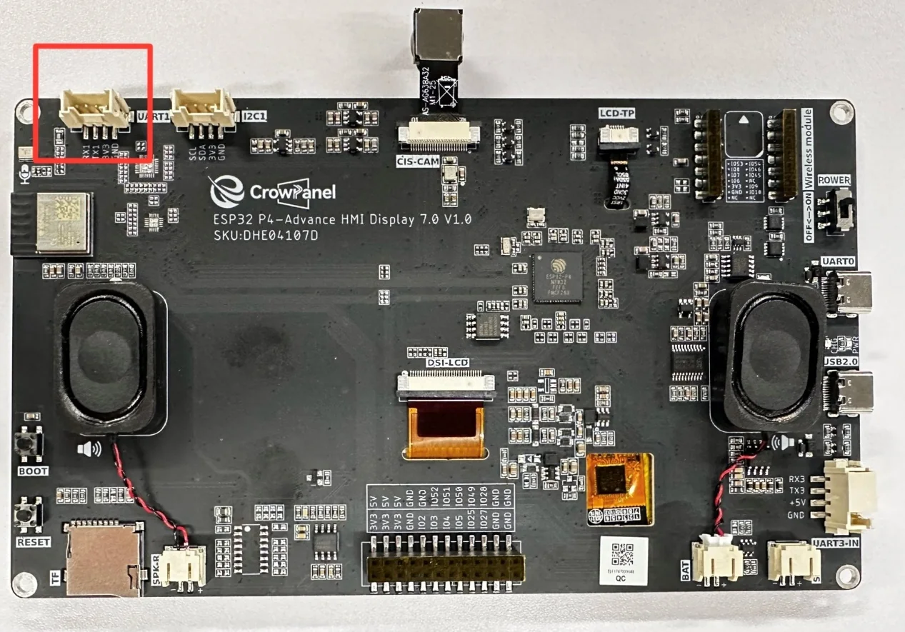
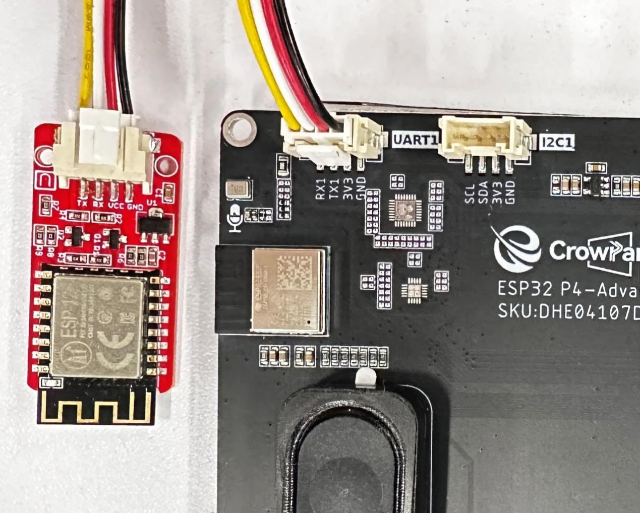
Then, connect an ESP8266 wifi module to the UART1 interface.
(Connect the VCC of UART1 interface to the VCC pin of the wifi module)
(Connect the GND of UART1 interface to the GND pin of the wifi module)
(Turn the TX of UART1 interface to the RX pin of the wifi module) (Cross connection)
(Turn the RX of UART1 interface to the TX pin of the wifi module) (Cross connection)
5.2 Connect to Wi-Fi and Observe the Log
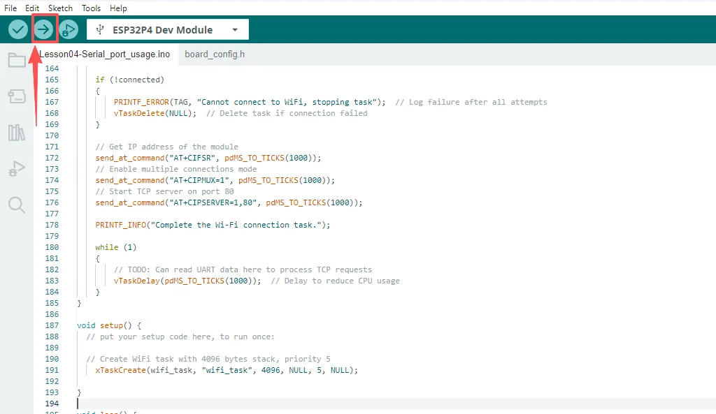
After connecting the development board to the computer, confirm that the module is inserted into the UART1 interface, verify the hardware connection is secure, and then upload the code.
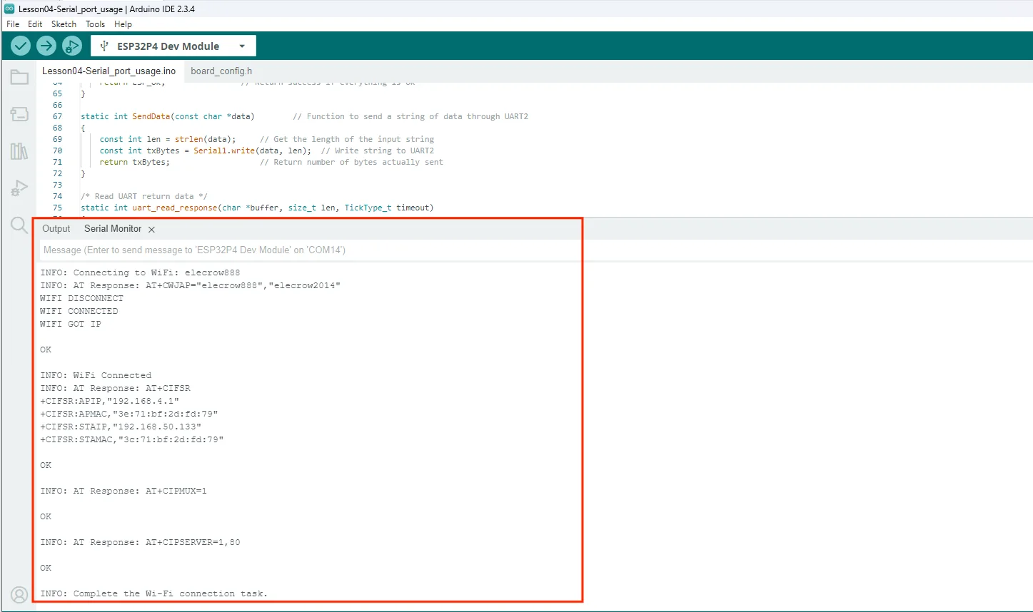
After the module is connected, open the Serial Monitor to observe the AT responses, IP address, and TCP service startup information.
(For how to open the Serial Monitor, please refer to Lesson 01, where we provide a detailed explanation.)
6. Key Code Explanation
6.1 UART Initialization and Response Reading
Serial.begin(115200);
Serial1.begin(115200, SERIAL_8N1,
              UART1_EXTRA_GPIO_RXD,
              UART1_EXTRA_GPIO_TXD);
uart_init() starts the UART0 debug port and UART1 on the board's extra RX/TX pins. uart_read_response() reads Serial1 until the timeout expires or the buffer is full, briefly yielding with vTaskDelay() when no data is available, and terminates the buffer with \0.
6.2 AT Command Encapsulation
SendData(cmd);
SendData("\r\n");
uart_read_response(response, AT_RESPONSE_MAX, timeout);
return strstr(response, "OK") != NULL;
send_at_command() wraps SendData(), the CRLF terminator, and uart_read_response() into a boolean result by searching the response for OK. connect_wifi() builds AT+CWJAP="SSID","PASSWORD" with snprintf() and sends it through this wrapper.
6.3 FreeRTOS Wi-Fi Task
send_at_command("AT+CWMODE=3", ...);
send_at_command("AT+RST", ...);
for (int i = 0; i < 5; ++i) {
  if (connect_wifi()) break;
}
wifi_task() first initializes the serial port, sets AP+STA mode, and resets the module, then retries network joining up to 5 times; upon success, it executes AT+CIFSR, AT+CIPMUX=1, and AT+CIPSERVER=1,80.
7. Experimental Observations
- The log displays UART initialization, AT response, successful Wi-Fi connection, and TCP service startup messages.
8. Common Issues and Troubleshooting
- If there is no response, first confirm whether TX/RX are cross-connected; if only
ATappears withoutOK, check the module's firmware baud rate. - If the connection fails, check the SSID/password, antenna, and module power supply.