Lesson 07: Lighting Up the Screen and Displaying Text with LVGL
Applicable Development Board: CrowPanel Advanced 7 / 9 / 10.1inch ESP32-P4 HMI AI Display
Model Compatibility: The 7-inch, 9-inch, and 10.1-inch models are fully interchangeable in terms of both hardware interfaces and software code; only their physical dimensions differ. Please select a model based on your actual display size and use case. No code modification is required for this lesson.
1. Course Introduction
Initialize the MIPI-DSI display, GT911 touch, and LVGL 9.1, and create a white background with a centered Hello Elecrow label.
2. Learning Objectives
By the end of this lesson, you should be able to:
- Understand the role of
board_config.hin binding the screen, touch, and LDO. - Understand LVGL locks, labels, styles, and centered layout.
- Make the screen stably display text.
3. What You Need to Prepare
- Prepare the CrowPanel Advanced 7 / 9 / 10.1inch ESP32-P4 HMI AI Display board and a data-capable USB-C cable in the quantity required for this lesson.
- The display panel resolution is 1024×600.
Code reference: https://github.com/Elecrow-RD/CrowPanel-Advanced-7inch-ESP32-P4-HMI-AI-Display-1024x600-IPS-Touch-Screen/tree/master/example
4. Software Operation Steps
Double-click to open the Lesson 7 code. (.ino file)
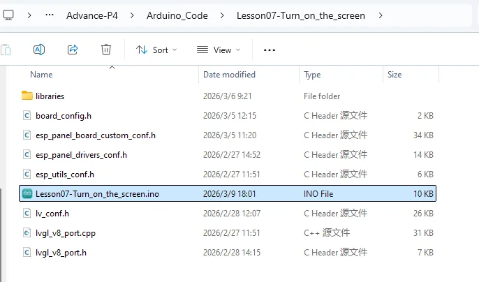
board_config.h centrally defines the GT911's I2C/reset/interrupt pins, the LCD backlight/reset pins, and the MIPI-DSI timing.

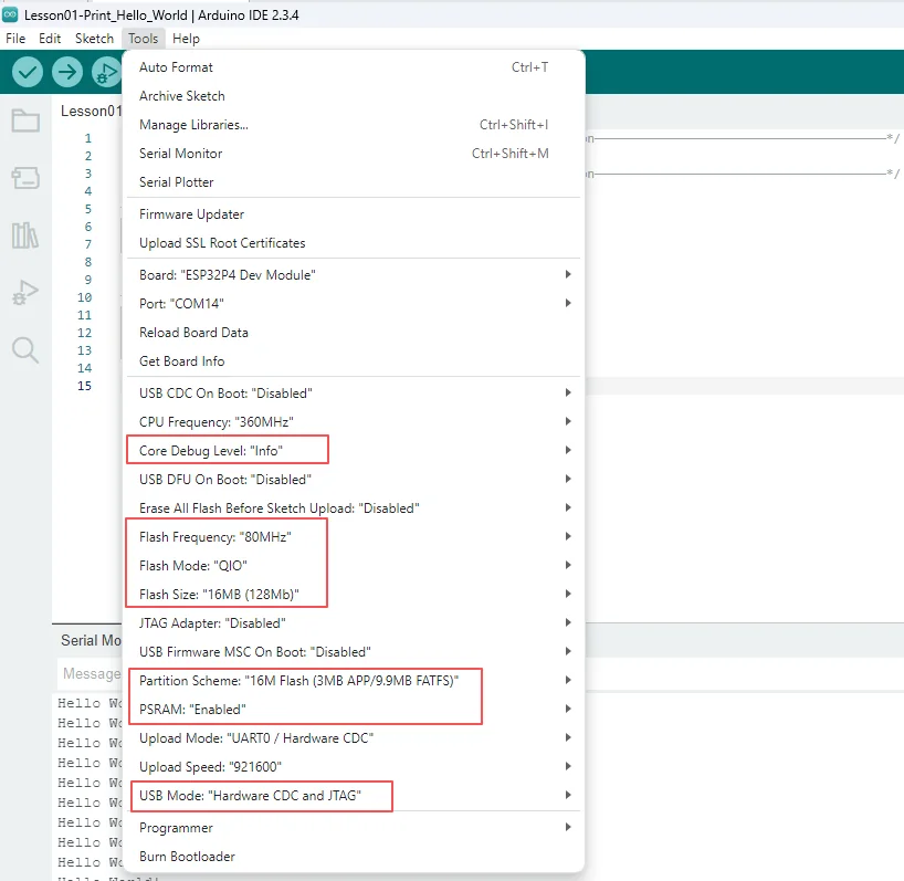
Configure the relevant options as follows.
- Board:
ESP32P4 Dev Module - Core Debug Level:
Info - Flash Frequency / Mode / Size:
80MHz/QIO/16MB (128Mb) - Partition Scheme:
16M Flash (3MB APP/9.9MB FATFS) - PSRAM:
Enabled - USB Mode:
Hardware CDC and JTAG - Port: After connecting the USB data cable to the board's UART0, select the newly appeared COM port under "Tools → Port".
Follow the library import steps explained in detail in Lesson 1 to import the library files required by this project into the development environment, ensuring that the code can correctly locate the relevant dependencies during compilation, thereby guaranteeing proper program operation.

5. Hardware Operation Steps
Now that the code is ready, we need to flash the ESP32-P4 to see the results in action.
First, connect the Advance-P4 device to your computer host via a USB cable.
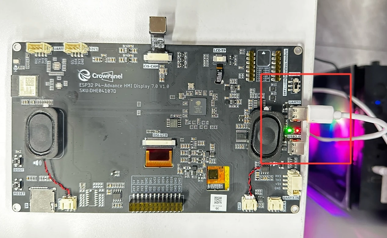
Before uploading the code, first select the upload configuration according to "4. Software Operation Steps".
Connect UART0, compile and upload using the general configuration; keep the board powered.
After running the code, you will be able to visually see that "Hello Elecrow" is displayed on the screen of the Advance-P4.

6. Key Code Explanation
6.1 lvgl_show_hello_elecrow()
if (lvgl_port_lock(-1) != true) return;
lv_obj_t *screen = lv_screen_active();
lv_obj_t *label = lv_label_create(screen);
lv_label_set_text(label, "Hello Elecrow");
lv_obj_center(label);
lvgl_port_unlock();
The function checks the lock result, sets a white opaque background, creates and validates the label, applies the size-42 Montserrat/black-text style, centers it, and unlocks LVGL. LVGL object changes must remain inside the lock.
6.2 Display and Touch Initialization
const bool board_init_ok = board->init();
assert(board_init_ok);
const bool board_begin_ok = board->begin();
assert(board_begin_ok);
lvgl_port_init(board->getLCD(), board->getTouch());
display_touch_lvgl_init() initializes the MIPI-DSI panel and GT911 touch controller, configures the LCD frame-buffer count when tearing avoidance is enabled, checks board->begin(), and passes the LCD/touch handles to lvgl_port_init().
7. Experimental Observations
- After the backlight turns on, the black
Hello Elecrowtext appears at the center of the screen
8. Common Issues and Troubleshooting
- If the screen is black, check LDO3/LDO4, the display ribbon cable, and the backlight.